Week 11 - Final project
Aim:
To Creation of CAD model considering Class A Surface, Nominal thickness, and Attachment strategy.
Objective:
To Creation of CAD model considering Class A Surface, Nominal thickness, and Attachment strategy.
Create the mounting features as per design guidelines in the industry and with master sections
Apply material details
Draft analysis & Tooling analysis
Procedure:
1. Import the file:
File > open > Browse file > and select the given file shown in the figure
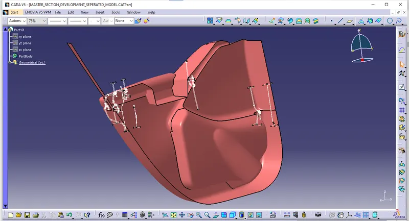
2. Class A Surface modification as per master section:
From the given data we have to do a cad model for Lower Substrate, Armrest and Map Pocket
A. LOWER SUBSTRATE:
Given lower substrate class A along with master surface is shown in the figure.
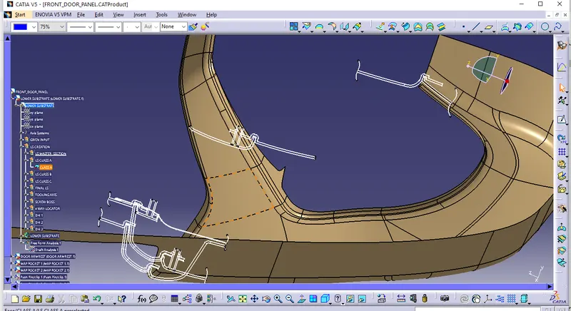
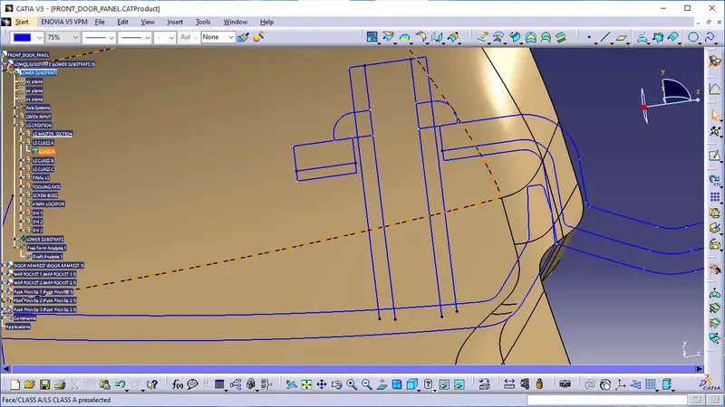
B/w Lower Substrate and Armrest:
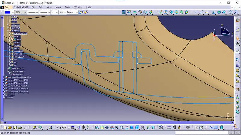
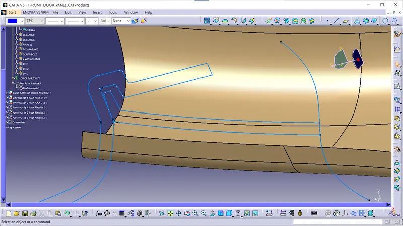
B/w Lower Substrate and Map Pocket:
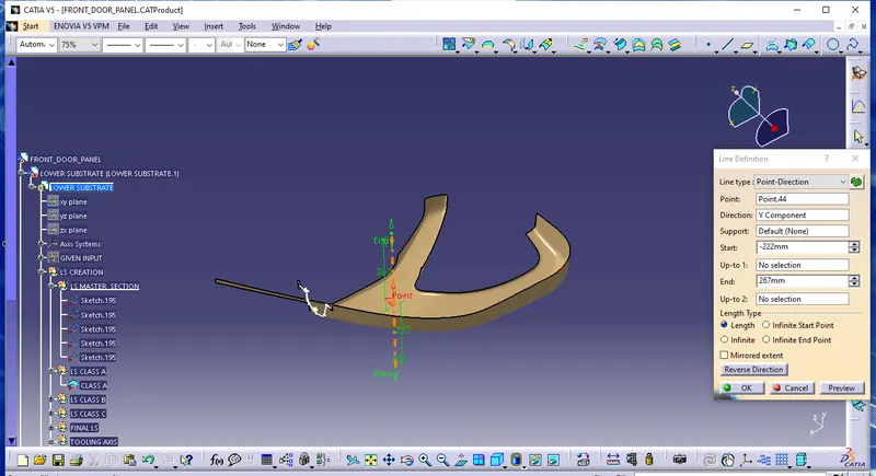
Tooling Axis Creation for Lower substrate:
Draft Analysis for Lower substrate:
Find the tooling axis for surface performing draft analysis using draft analysis tool(Insert > analysis > draft analysis).
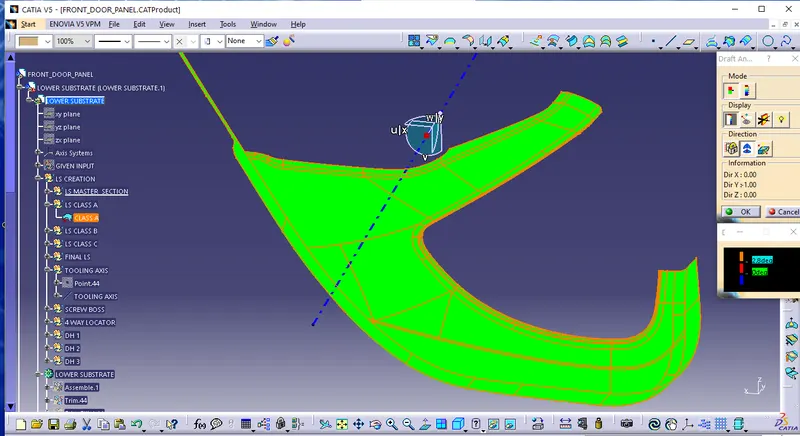
All faces of class A are drafted at 2.8 degrees.
So we need to add surface to class A by using the master section shown in the figure.
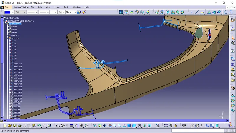
B. Map Pocket:
Given lower substrate class A along with master surface is shown in the figure.
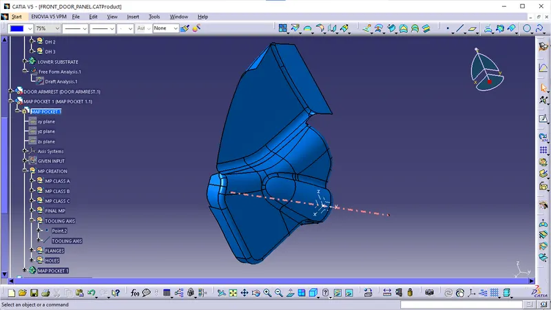
B/w lower Substrate and Map Pocket:
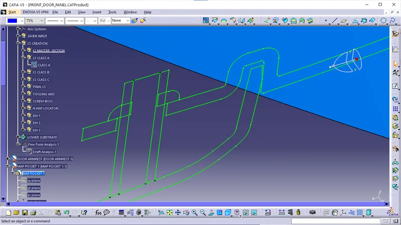
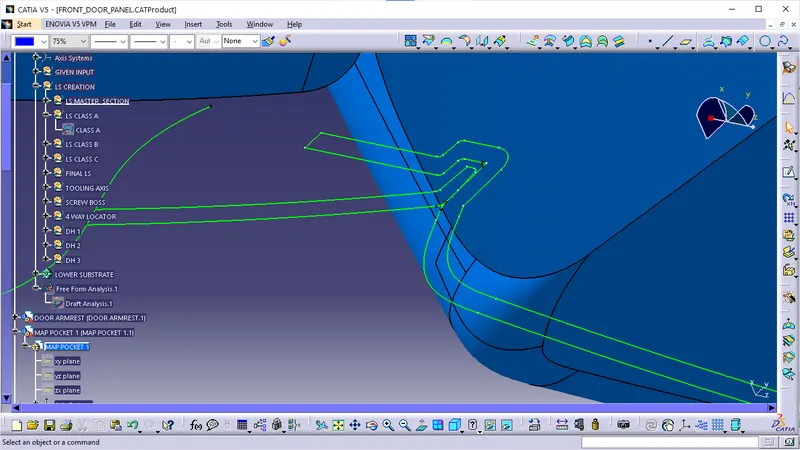
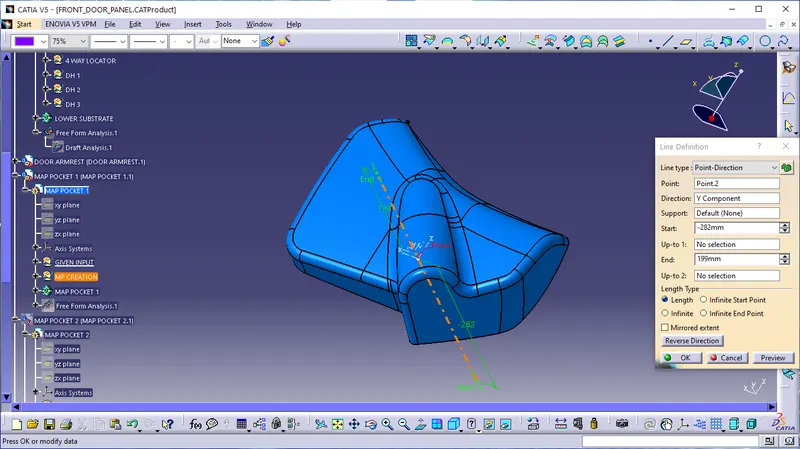
Tooling Axis for Map pocket 1:
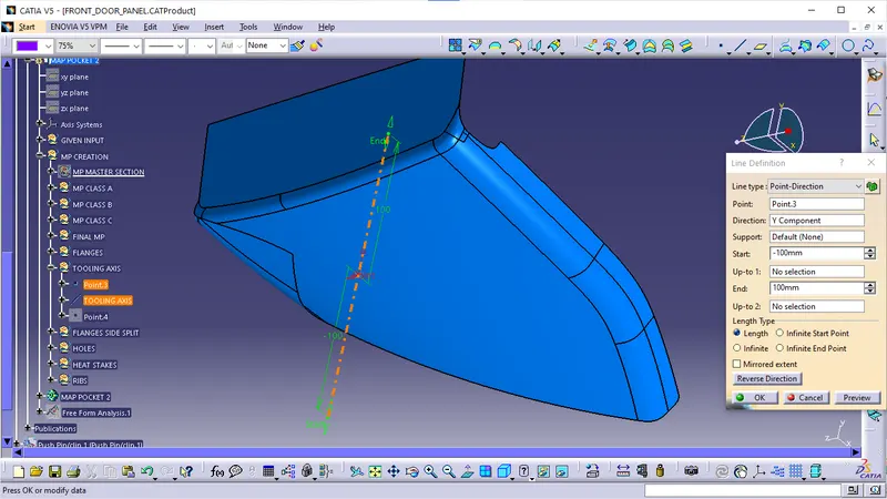
Tooling Axis for Map pocket 2:
Draft Analysis:
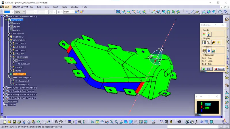
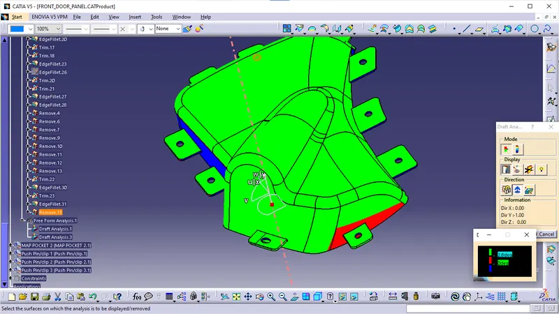
Map Pocket is divided into two parts. Find the tooling axis for surface performing draft analysis using draft analysis. tool(Insert < analysis > draft analysis) for two parts.
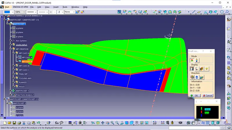
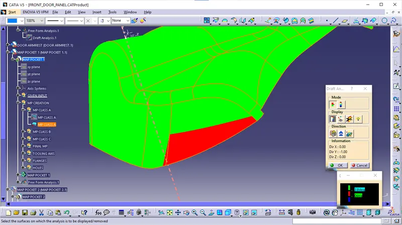
Draft Analysis for Map Pocket 1:
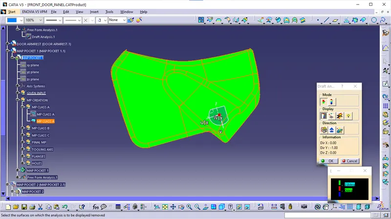
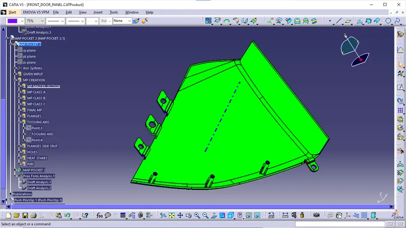
All areas are drafted at 2.8 degrees except some areas are not drafted as shown in the next images.
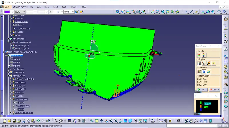
Draft Analysis for Map Pocket 2:
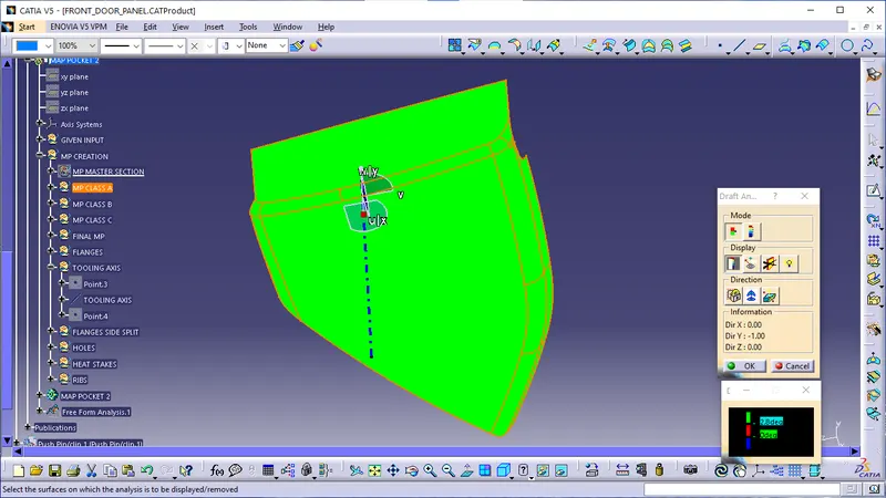
All areas of class A are drafted at 2.8 degrees.
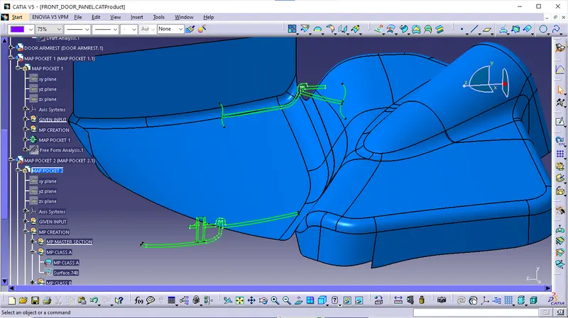
So we need to add a surface by using the master section is shown in the figure.
C. Armrest:
Given lower substrate class A along with master surface is shown in the figure.
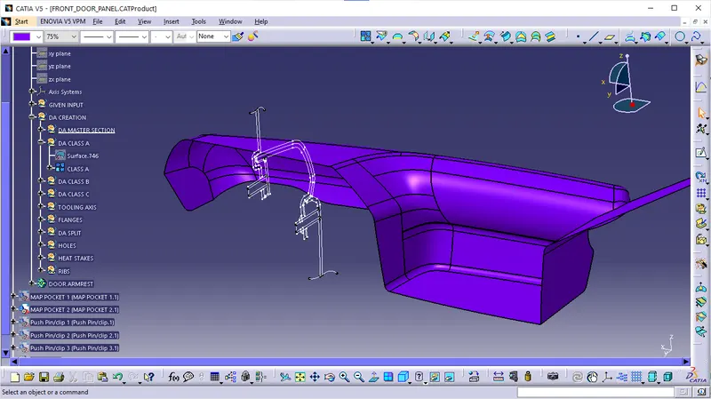
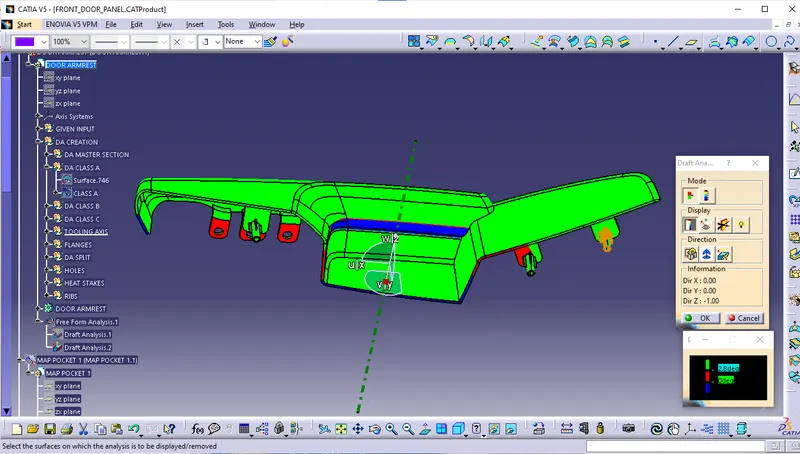
Slider Axis for Armrest:
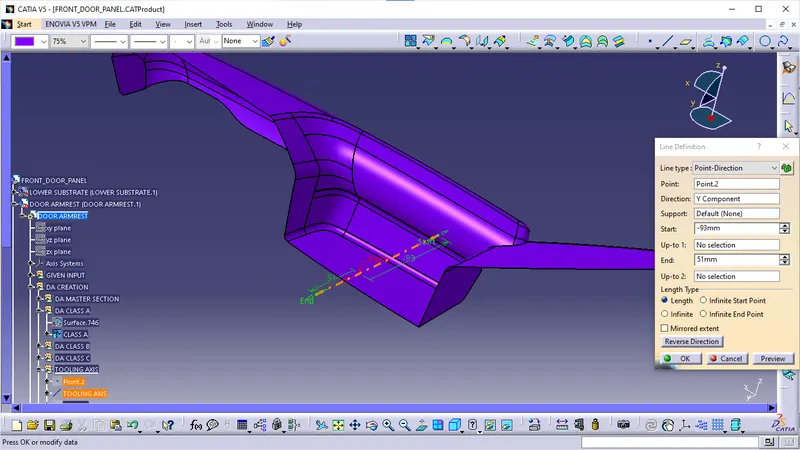
Draft Analysis for Armrest:
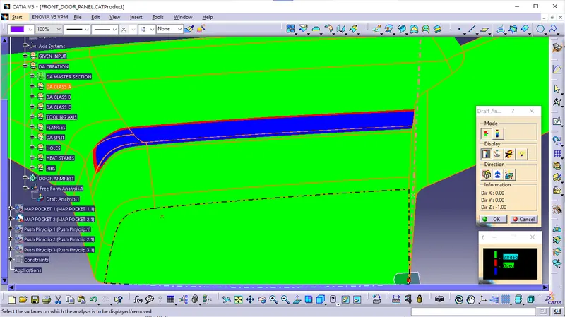
Find the tooling axis for surface by performing draft analysis using draft analysis tool (Insert > analysis >draft analysis).
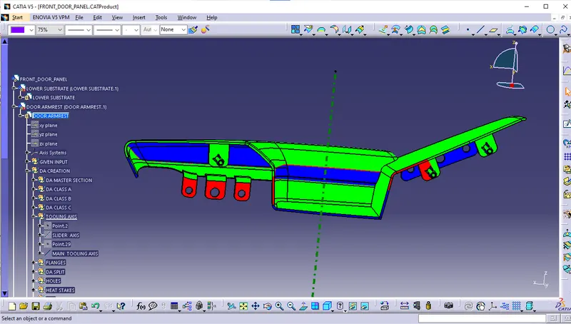
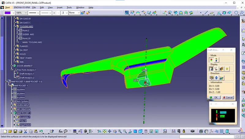
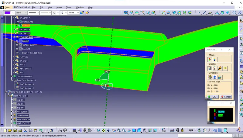
Draft Analysis for Class A with Slider Axis:
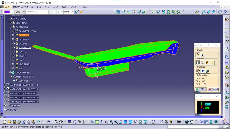
Draft Analysis for Class A with Main Tooling Axis:
2. Class B Surface:
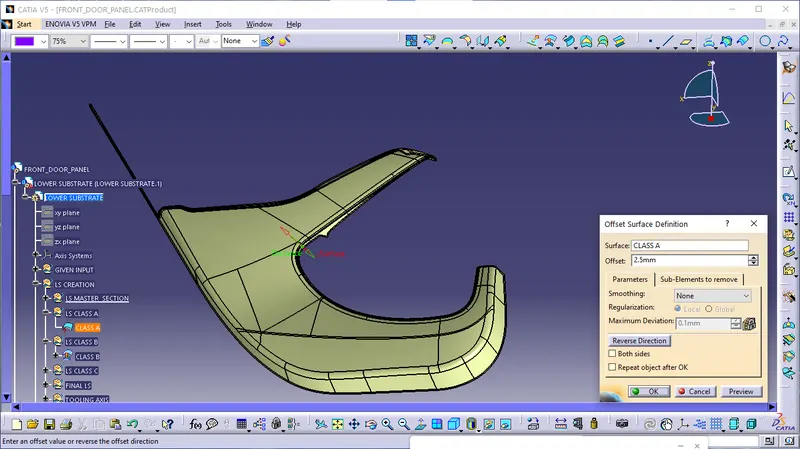
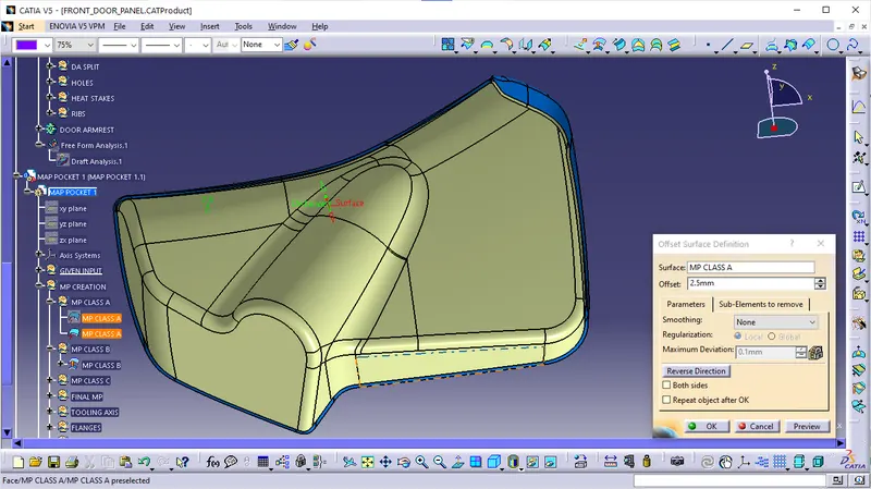
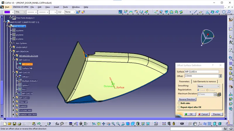
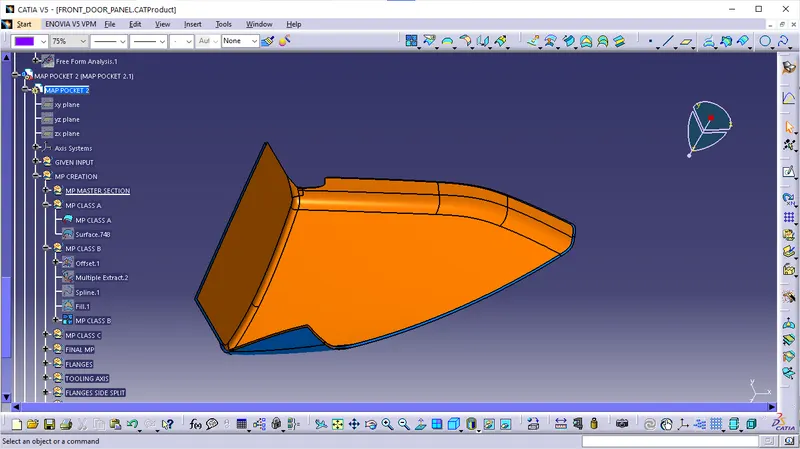
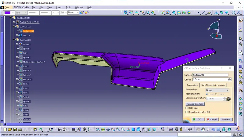
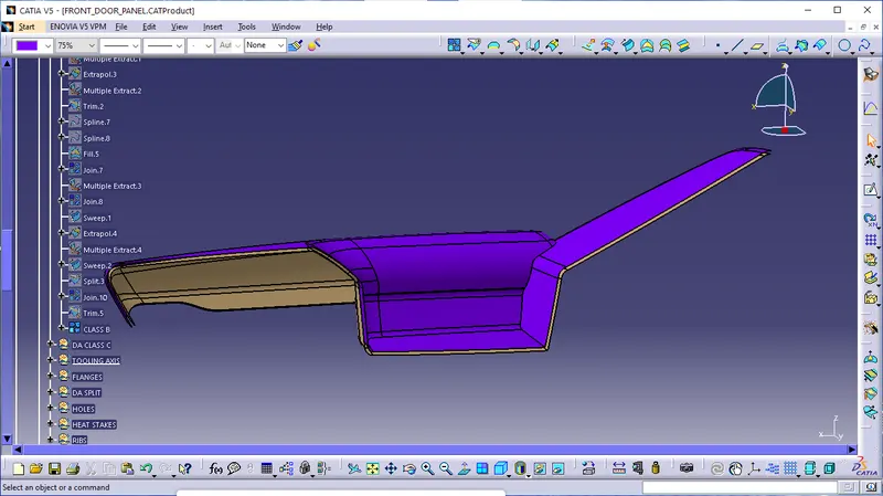
For All parts, Class B Surface is created by using offset and extrapolated.
Lower Substrate:
Map Pocket 1:
Map Pocket 2:
3. Class C Surface:
Class C Surfaces are created based on the tooling direction as well surface reference.
tools used
Creating Swept surfaces:
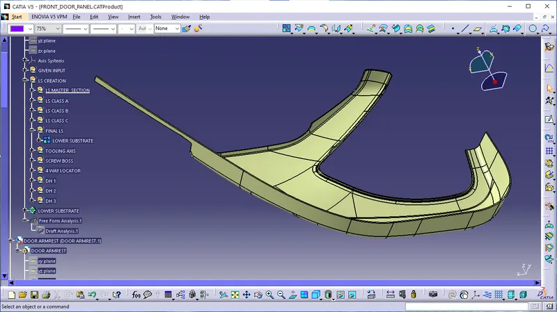
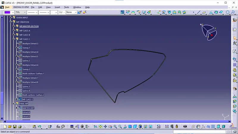
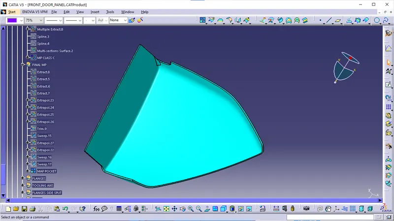
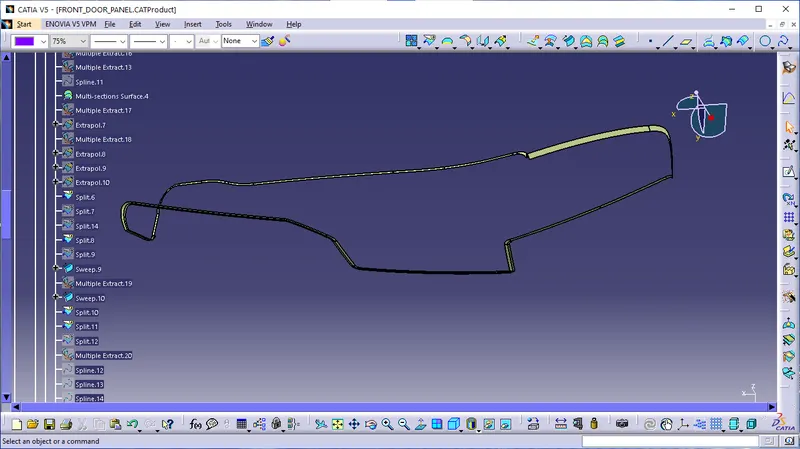
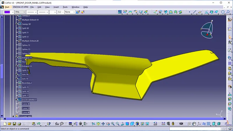
Class C surface was swept along the boundary of Class A using the ' Sweep' option at an angle of 3 degrees outwards with respect to tooling direction.
In some areas, the 90-degree sweep was applied.
Lower Substrate:
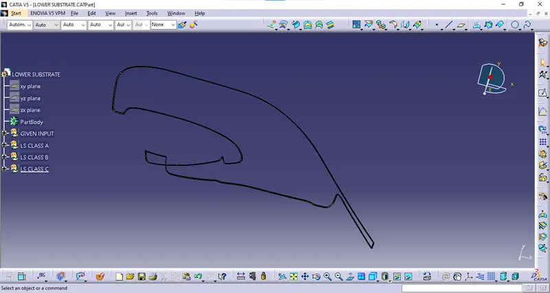
Finally, all the swept surfaces were trimmed and joined together.
Map Pocket 1:
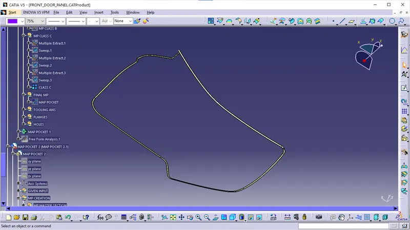
Finally, all the swept surfaces were trimmed and joined together.
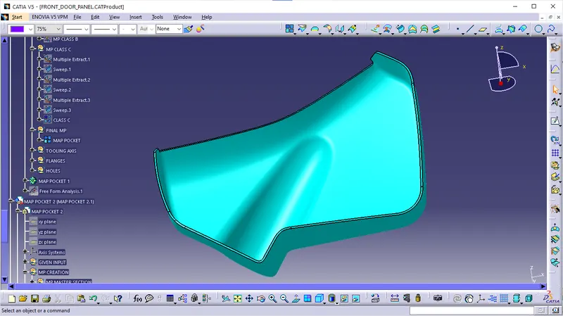
Map Pocket 2:
Armrest:
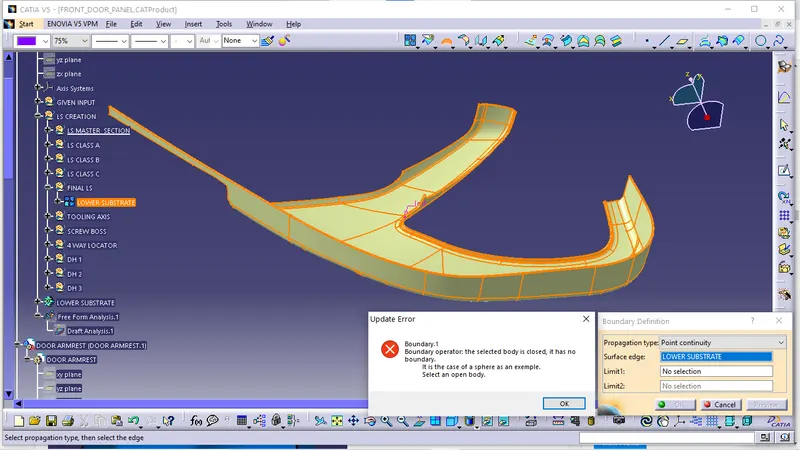
Check the boundaries:
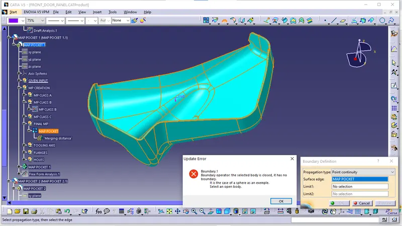
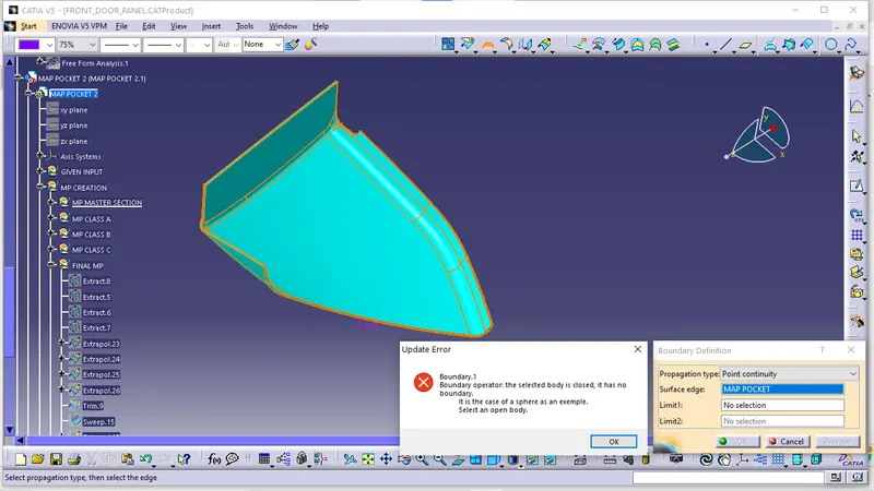
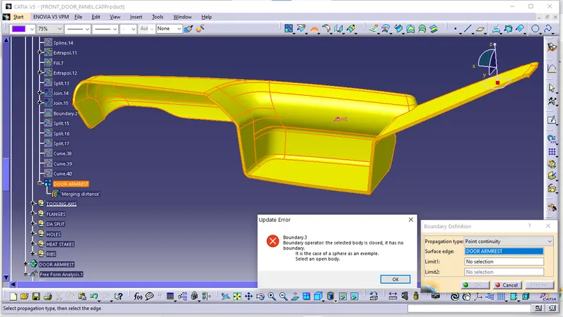
To make the plastic component a solid body we have to ensure that the component does not have any openings.
Boundary checking helps us to find if there are any openings present in the component.
Lower Substrate:
Map Pocket 1:
Map Pocket 2:
Armrest:
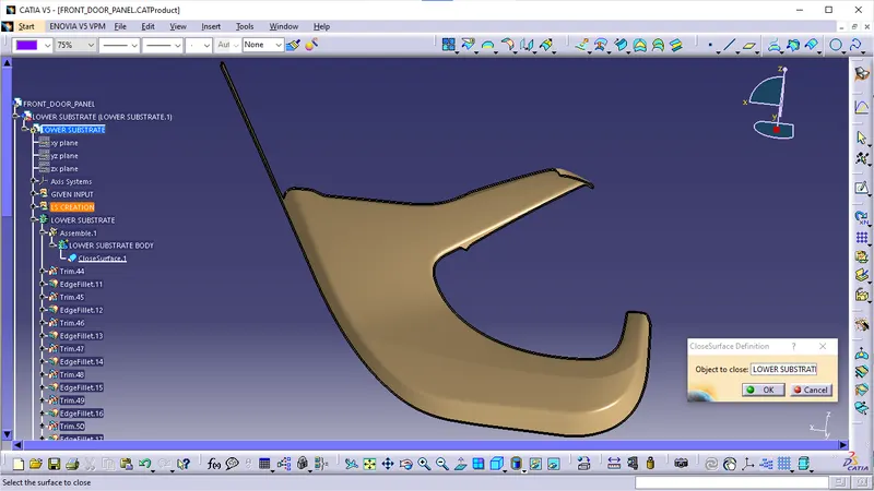
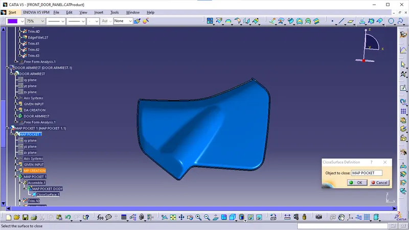
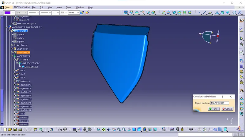
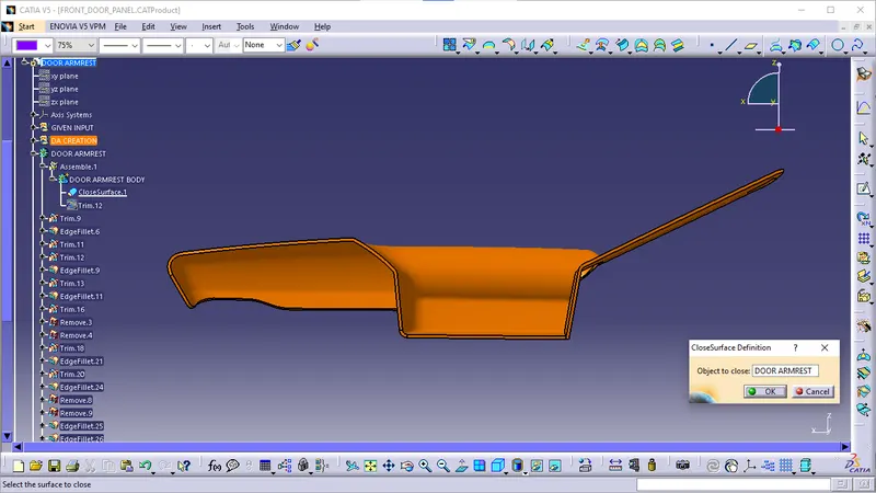
Creation of Solid Body:
Lower Substrate:
Map Pocket 1:
Map Pocket 2:
Armrest:
Creation of Attachment Features on B-Side:
Creation of Flanges:
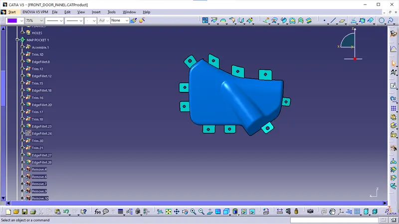
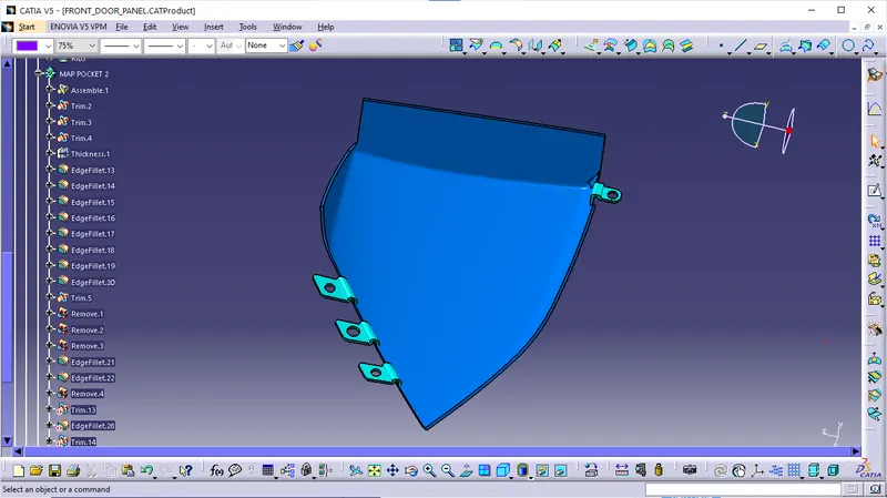
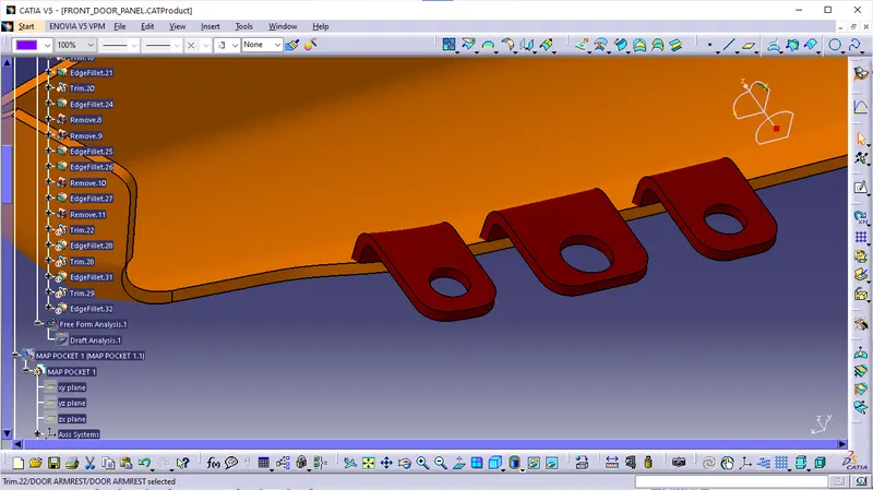
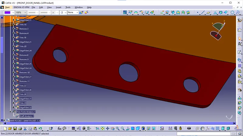
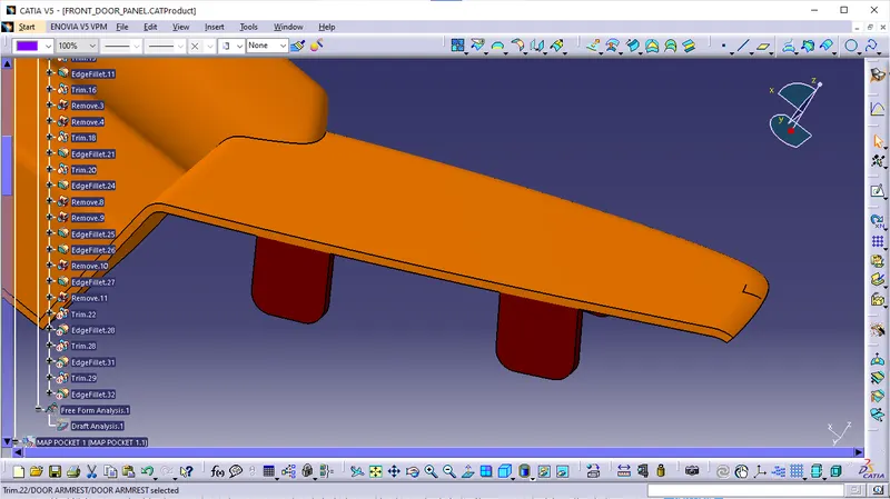
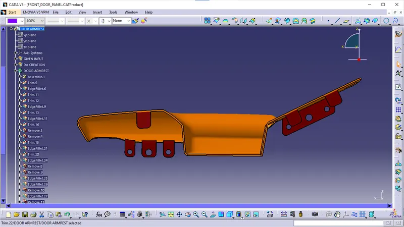
Flanges are created wherever required. Master sections are given so that the measurements are acquired and created as shown below.
Map pocket 1:
Map pocket 2:
Armrest:
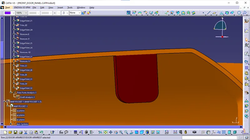
Armrest:
Design Rules of Screw Boss:
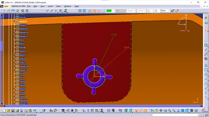
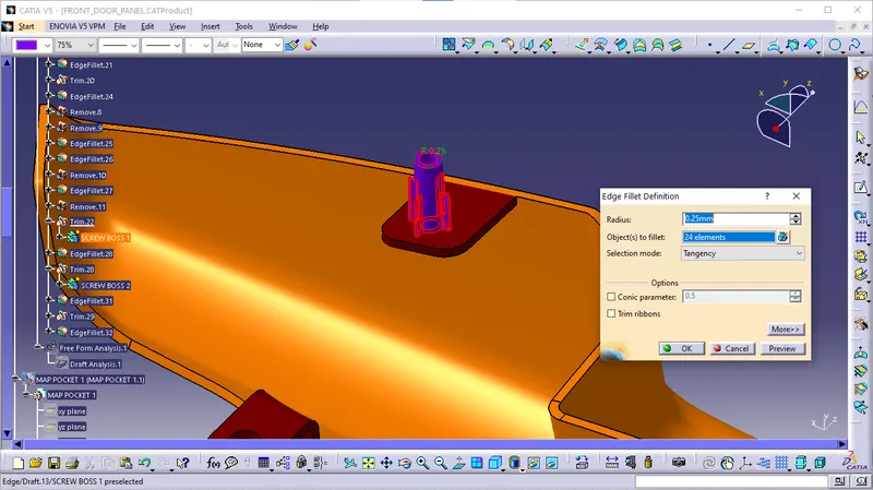
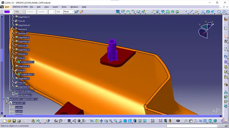
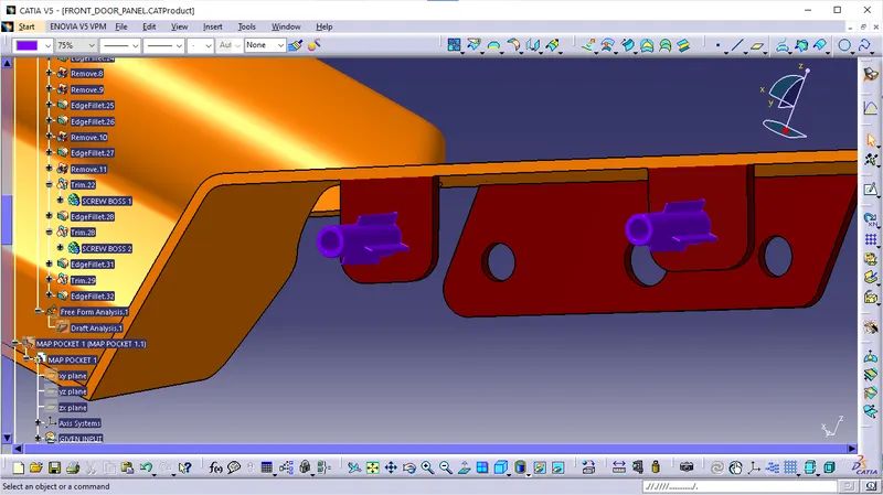
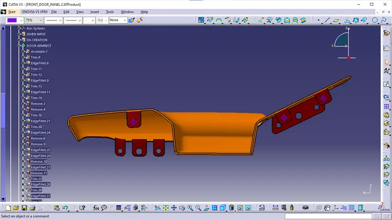
Screw Boss is created wherever required. Master sections are given so that the measurements are acquired and created as shown below.
Create attachment:
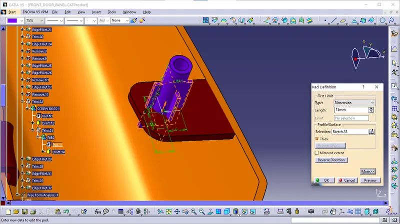
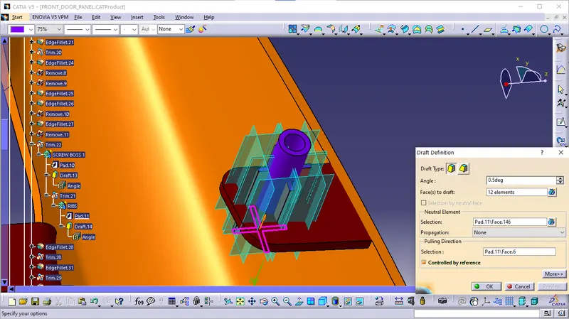
Heat stakes for the part to the part attachment as per master section, here some of the heat stakes are having ribs
Because they have more than 1.6 of Dia, so in order to give strength we have ribs. all heat stakes are done on Lower Substrate. shown in the figure.
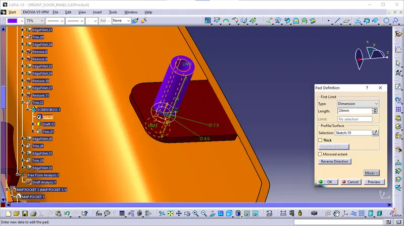
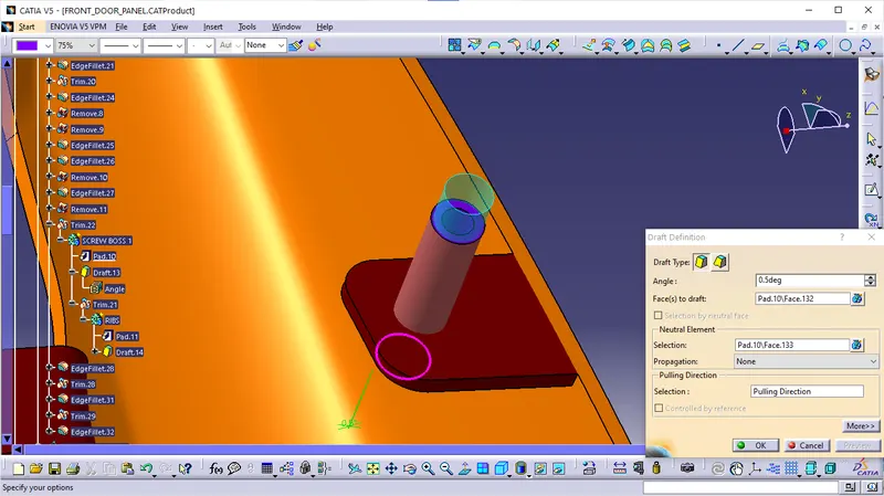
Screw Boss 1:
Screw Boss 2 & 3:
Lower Substrate:
Creation of Screw Boss:
Heat Stakes are created by using the master section on the lower substrate.
Heat Staking is a pulsed-heat process to join two or more parts out of which one at least is made of plastic.
The process is to deform the plastic material using heat and force at a set process time.
The bond is made by partially de-forming the plastic part in order to fix the other.
Heat Stakes are created on the lower substrate wherever the flanges are projected on the lower substrate.
Ribs are added up to flanges bottom position.
Create attachment:
Heat stakes for the part to the part attachment as per master section, here some of the heat stakes are having ribs
Because they have more than 1.6 of Dia, so in order to give strength we have ribs. all heat stakes are done on Lower Substrate. shown in the figure.
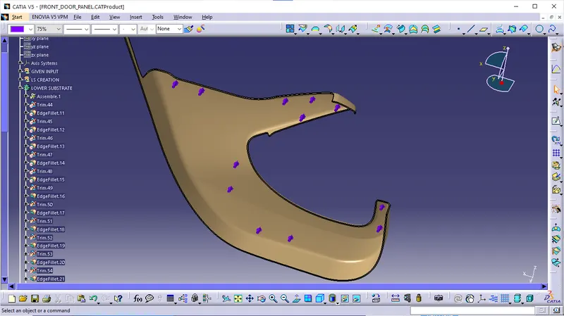
Heat Stakes are represented in violet colour.
Creation of 4 Way locator:
Create attachment:
4 Way locator for the part to the part attachment as per master section.
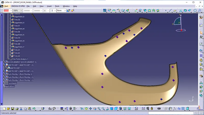
4 Way locators are represented in navy blue colour.
Map Pocket 2:
Creation of Screw Boss:
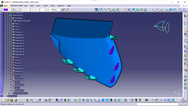
Heat stakes for the part to the part attachment as per the master section, here some of the heat stakes are having ribs.
Because they have more than 1.6 of Dia, so in order to give strength we have ribs. all heat stakes are done on a map pocket shown in the figure.
 .
.
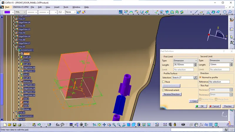
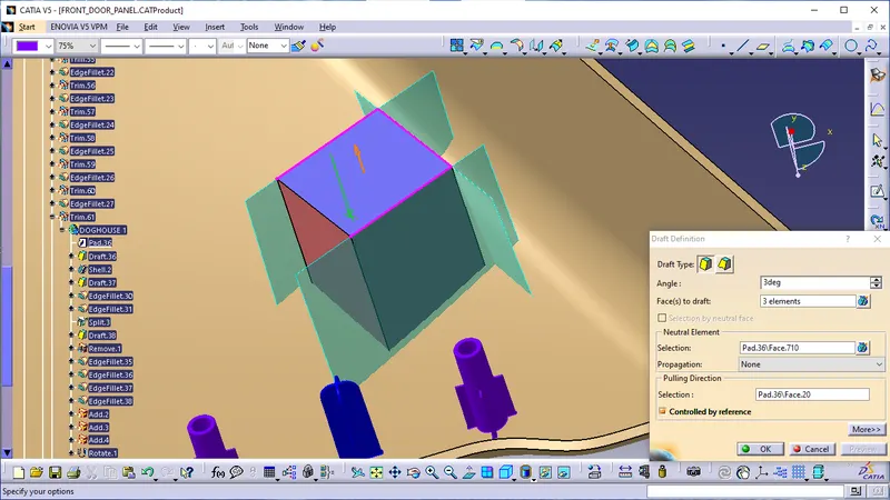
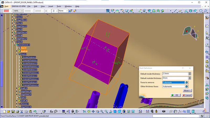
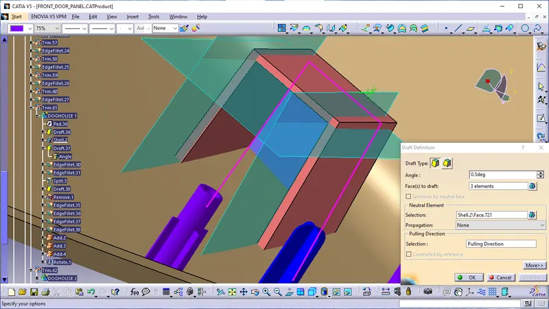
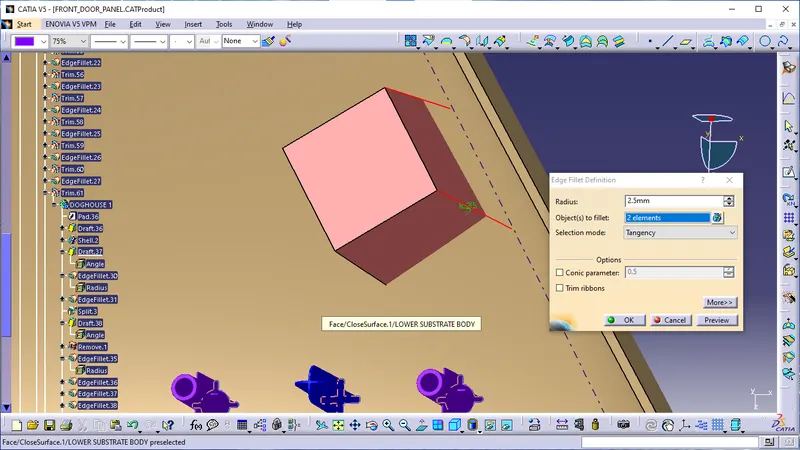
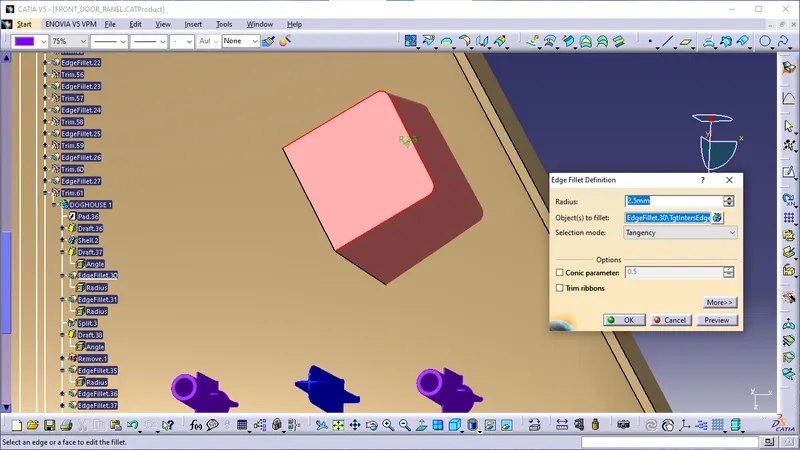
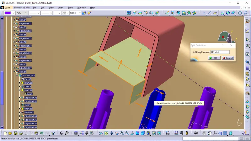
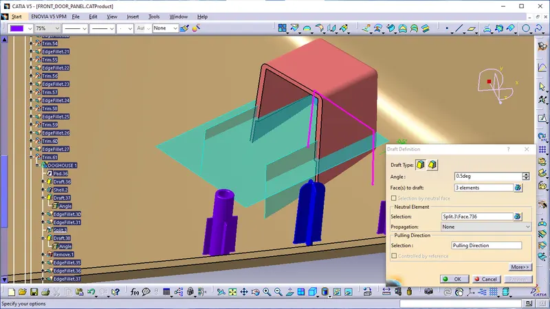
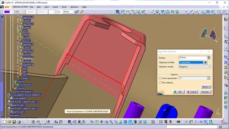
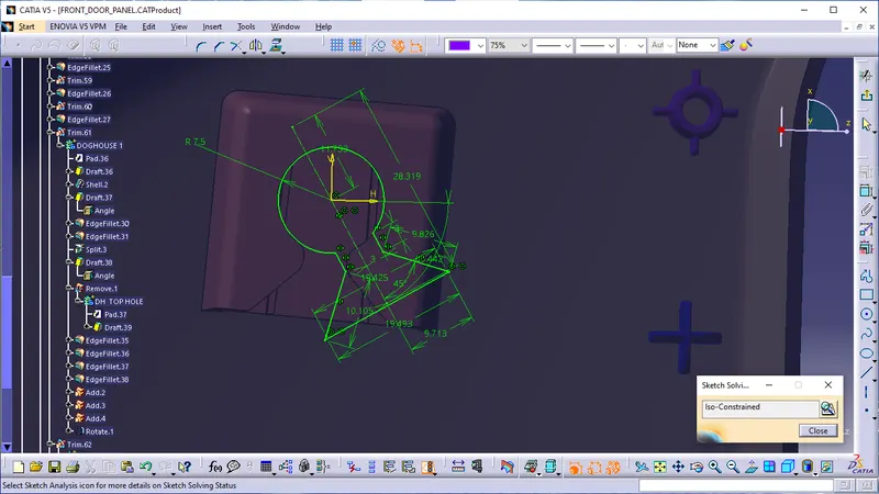
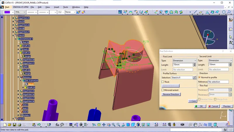
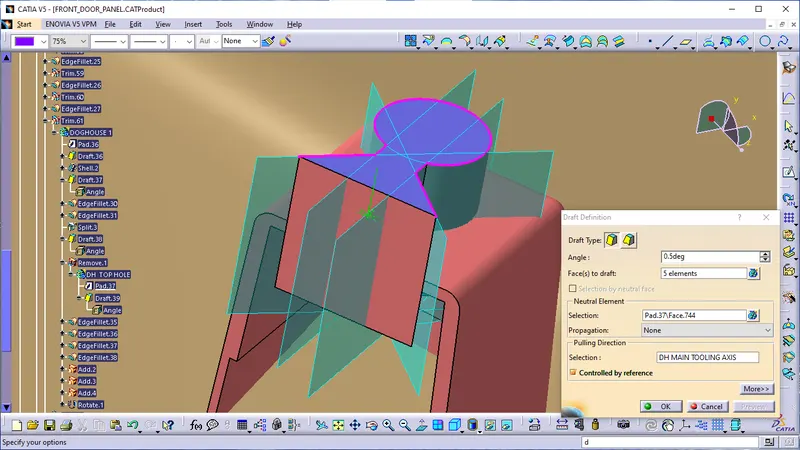
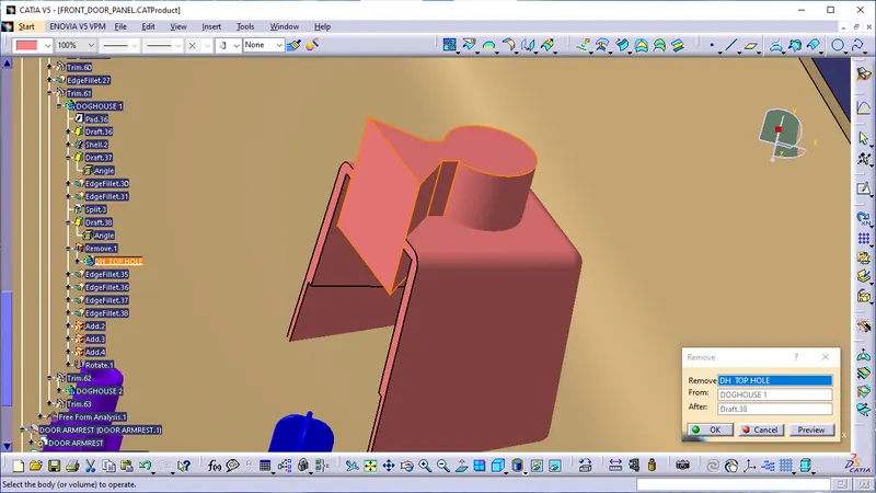
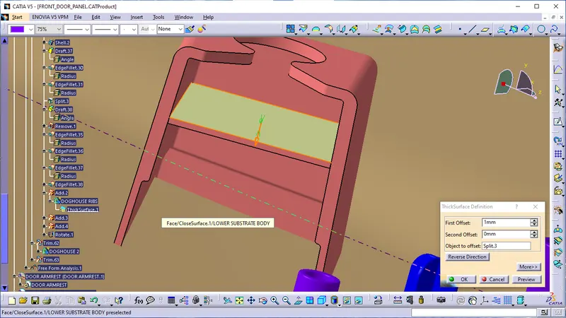
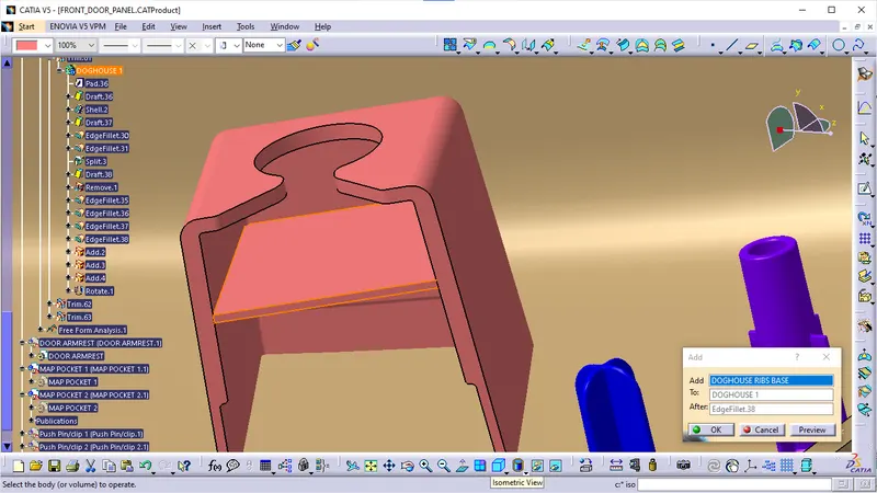
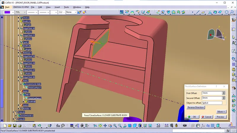
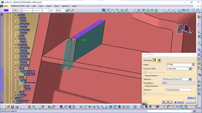
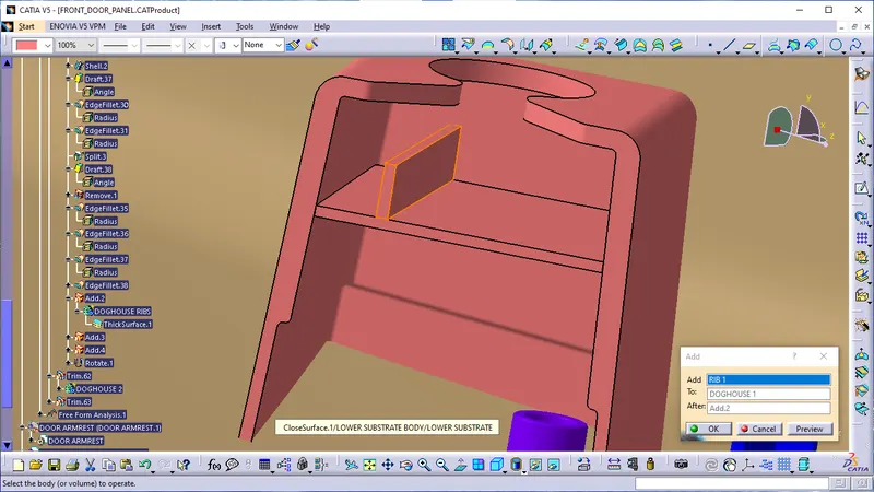
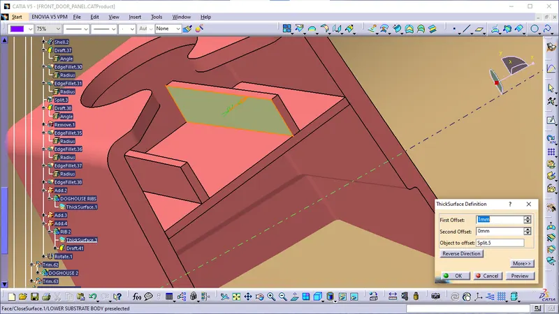
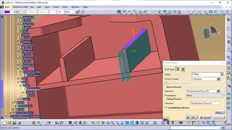
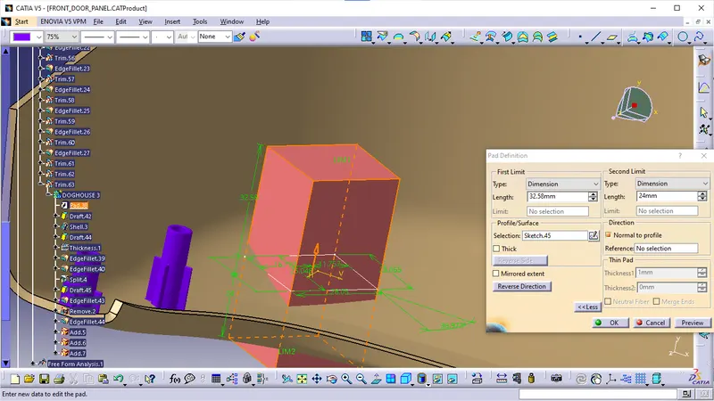
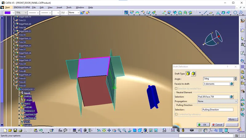
Creation of Doghouse:
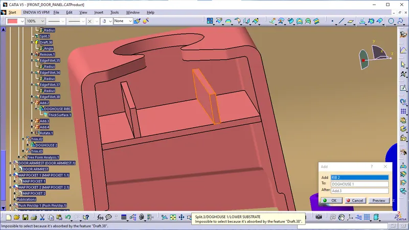
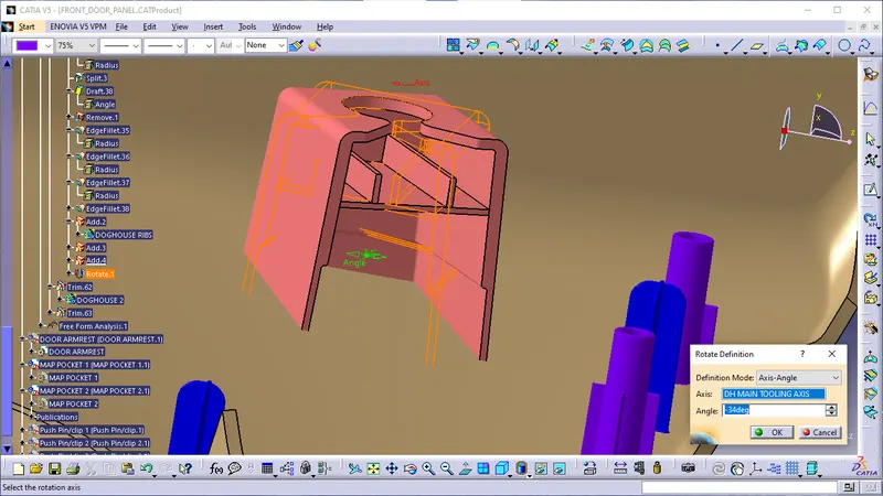
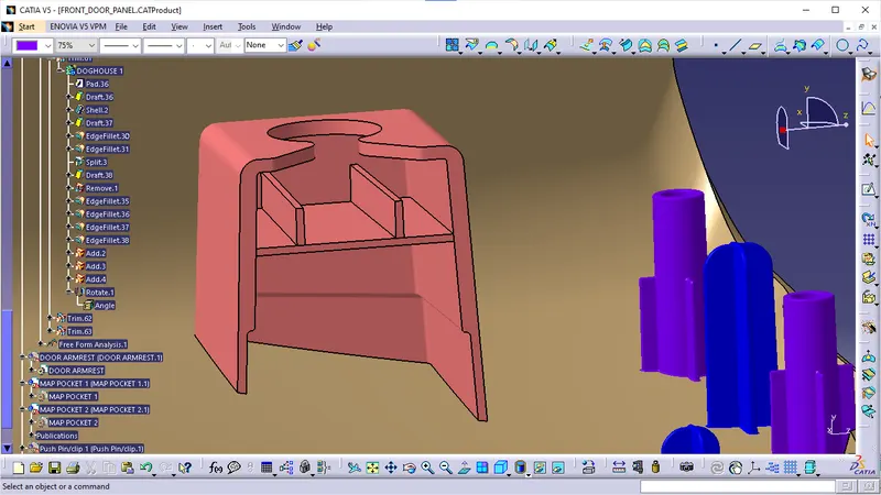
Doghouse 1
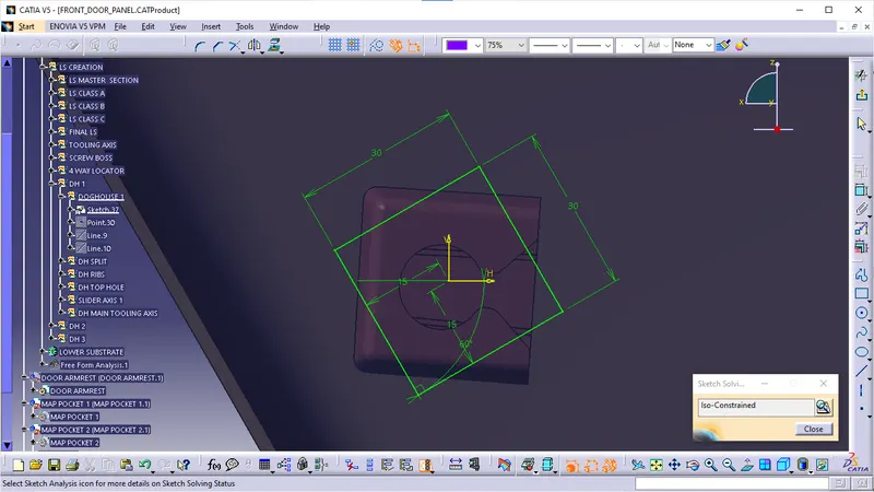
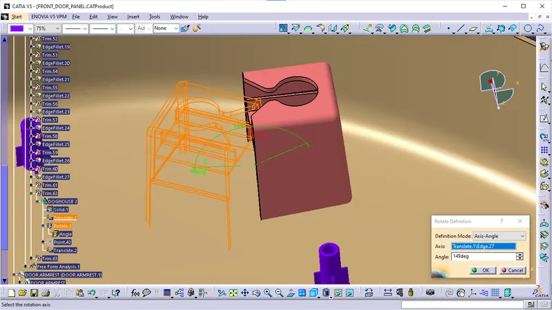
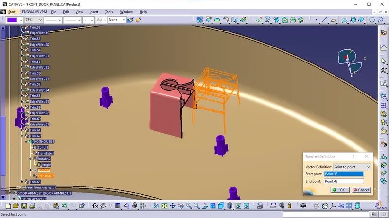
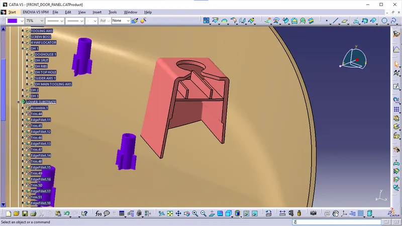
Doghouse 2:
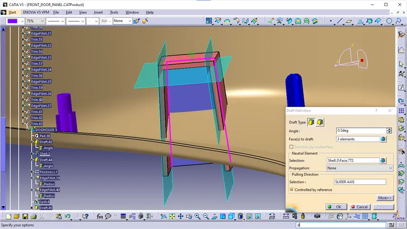
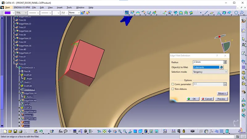
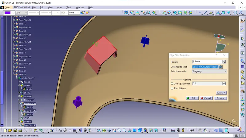
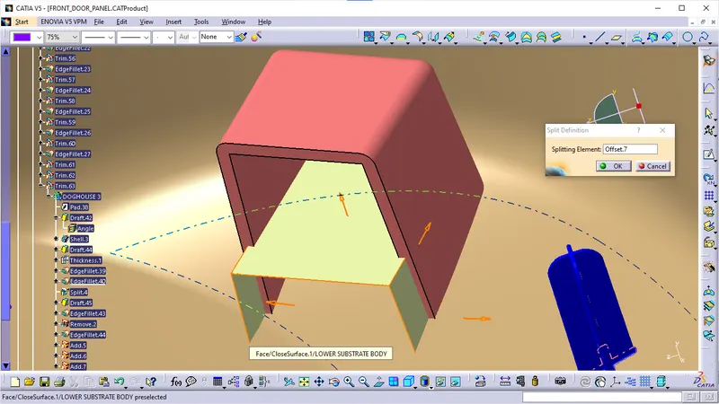
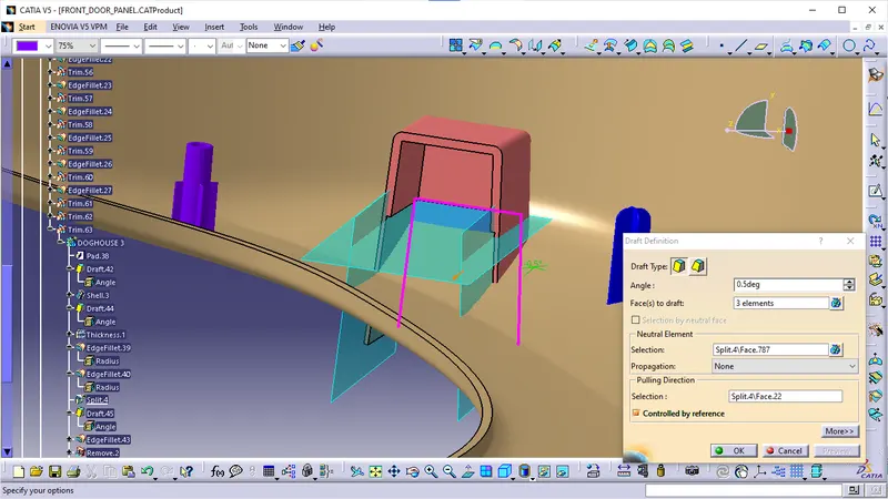
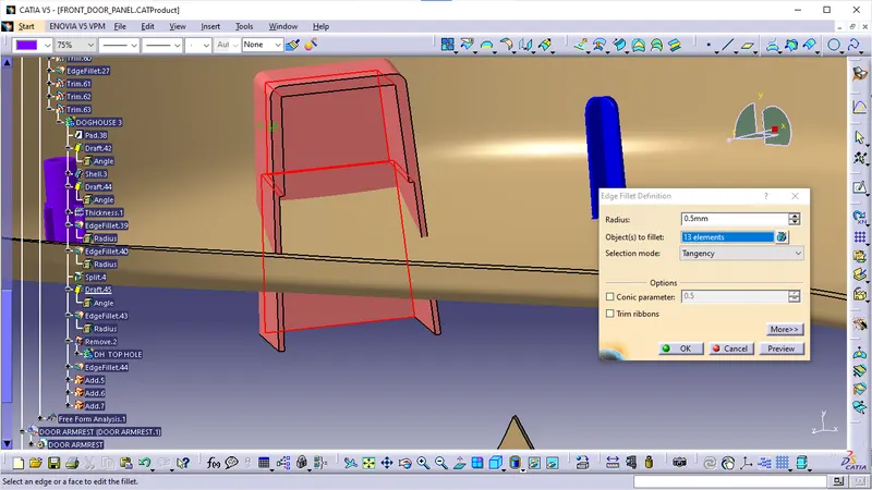
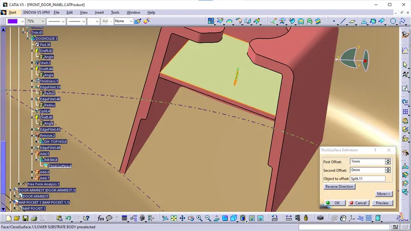
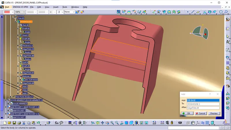
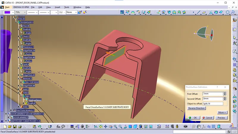
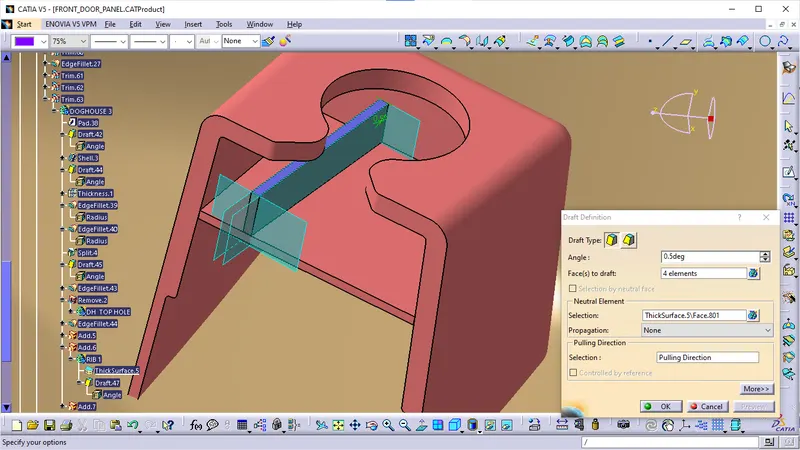
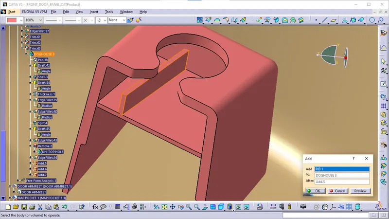
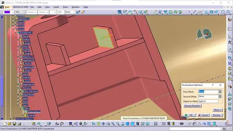
Doghouse 3:
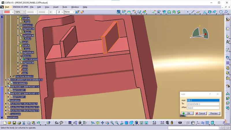
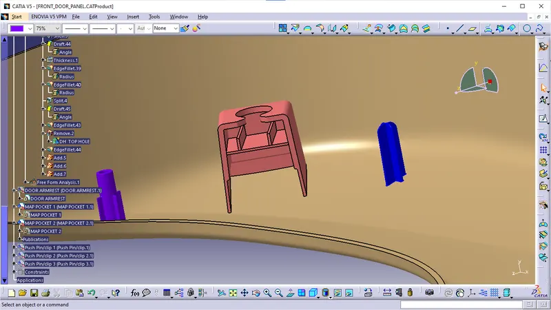
Final Doghouses:
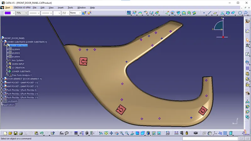
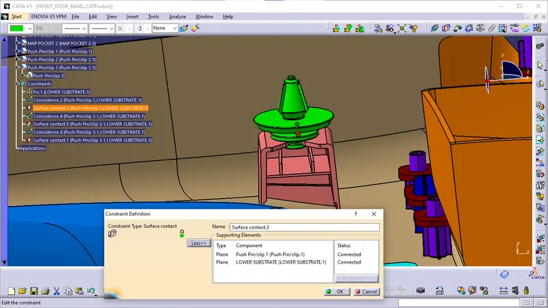
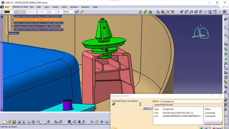
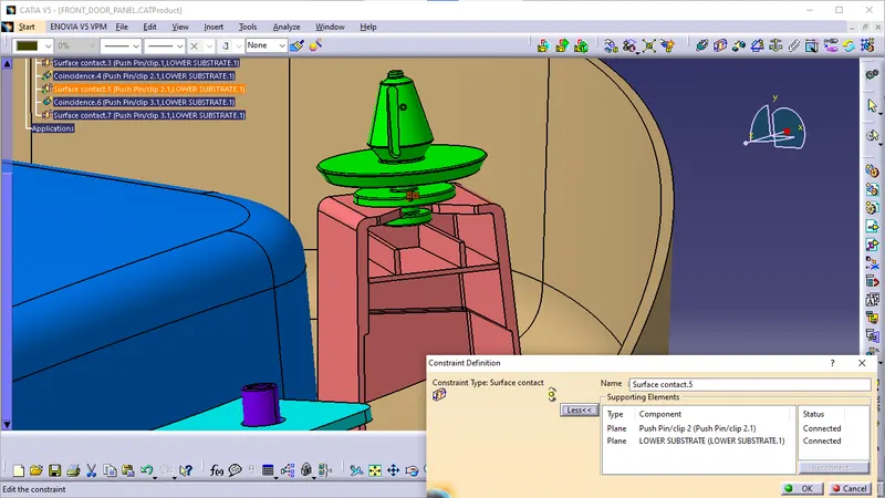
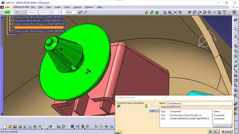
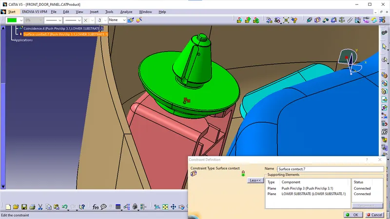
Push Pin for assembly of the panel with BIW part:
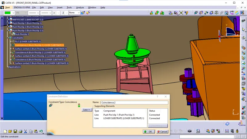
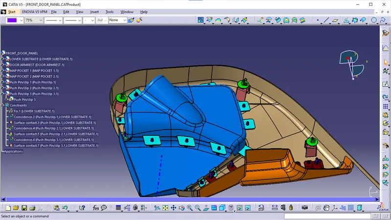
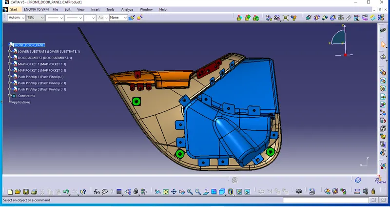
Final Front Door Panel :
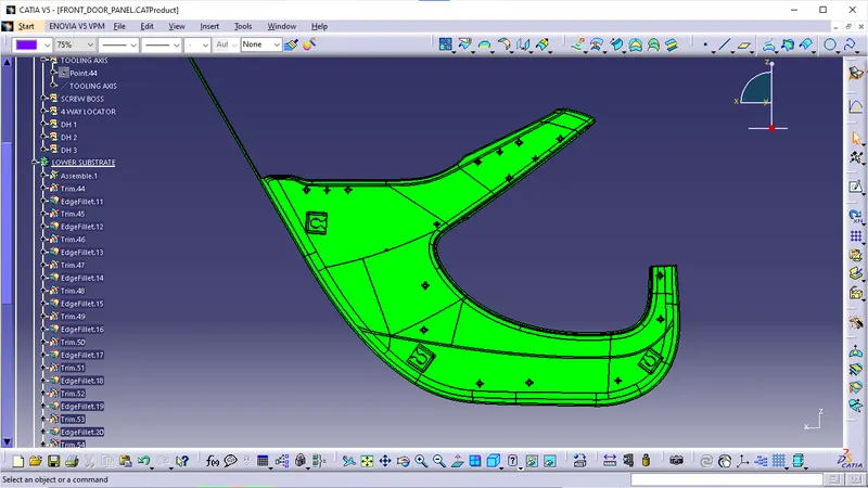
Final Draft Analysis:
Draft Analysis for Main Tooling Axis
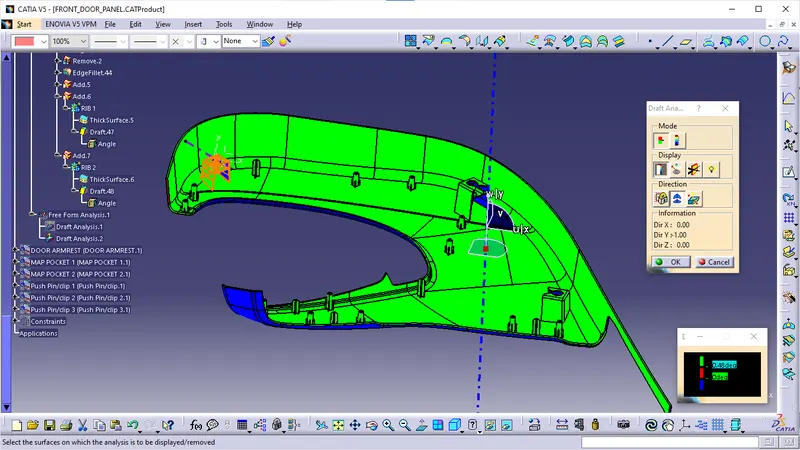
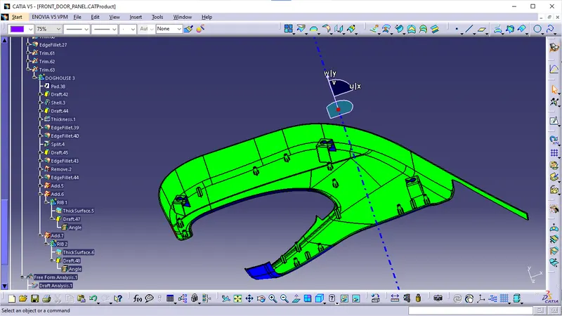
A. lower substrate:
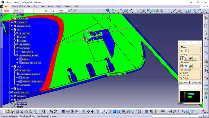
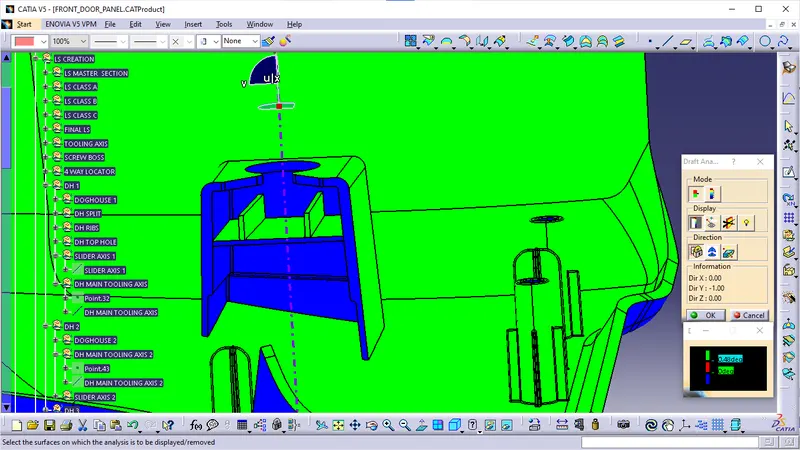
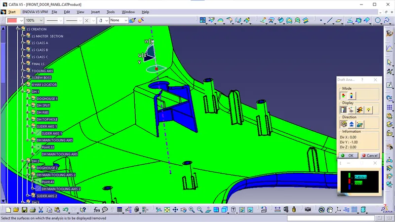
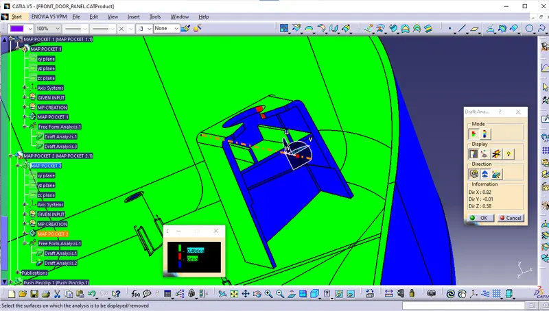
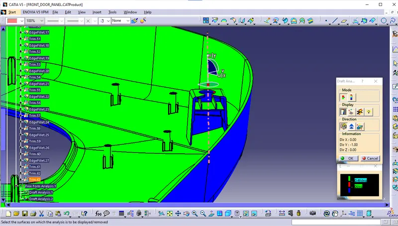
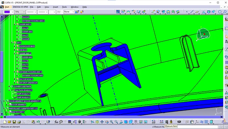
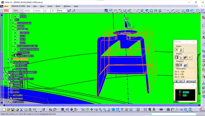
For All heat stakes and dog houses, the draft is given 0.5 deg. so we can see that blue colour.
Doghouse 1:
Draft Analysis for doghouse 1 with Slider Axis:
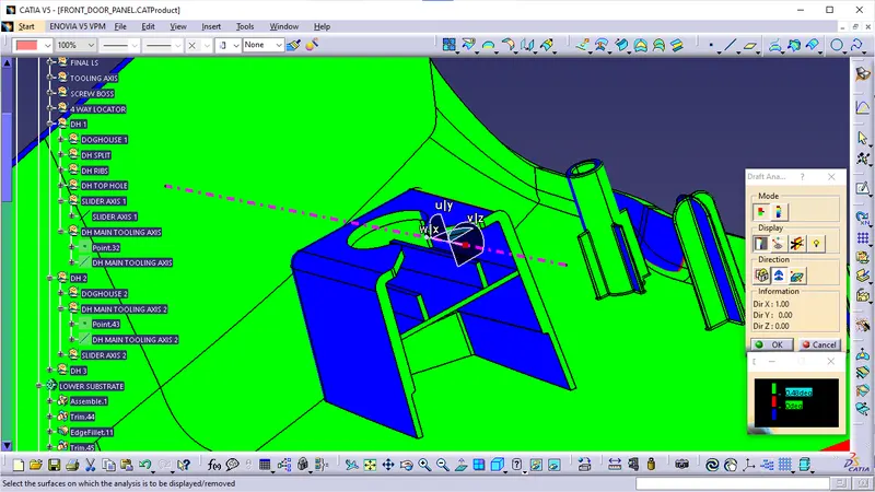
Draft Analysis for doghouse 1 with Main Tooling Axis:
Doghouse 2:
Draft Analysis for doghouse 2 with Slider Axis:
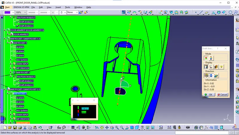
Draft Analysis for doghouse 2 with Main Tooling Axis:
Doghouse 3:
Draft Analysis for doghouse 3 with Slider Axis:
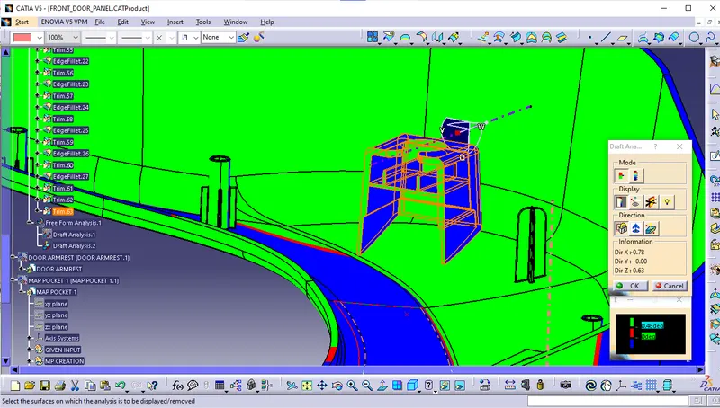
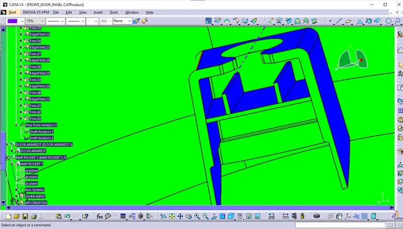
Draft Analysis for doghouse 3 with Main Tooling Axis:
Map Pocket 1:
Map Pocket 2:
 .
.
Armrest
Draft Analysis for Armrest with slider axis:
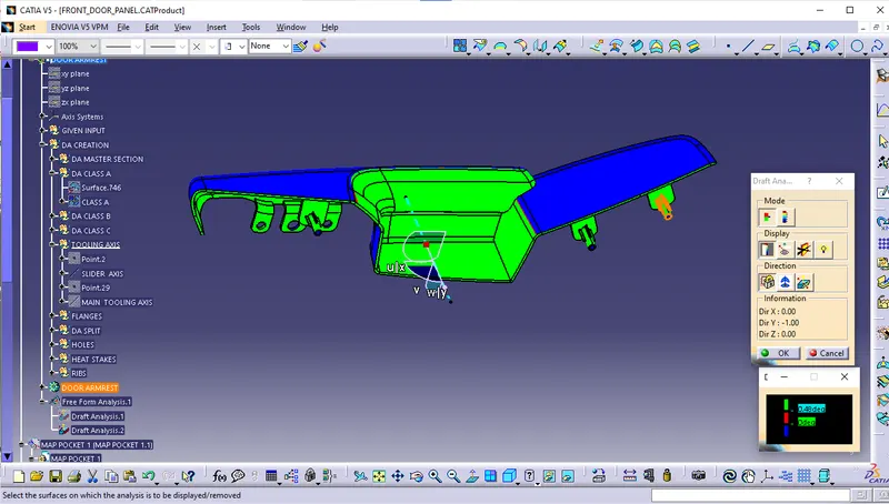
Draft Analysis for Armrest with Main Tooling axis: