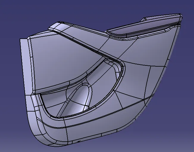
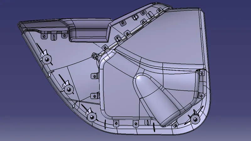
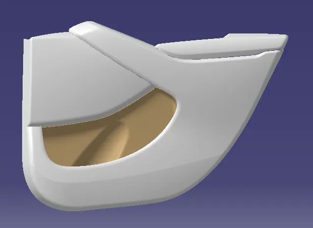
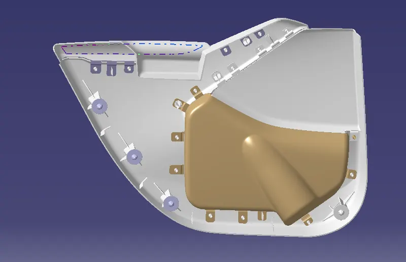
Week 11 - Final project
Aim:
Developing a door trim panel and creating a computer aided design model with considering the following inputs from class a surface and Master section.
Inputs:
- class A surface
- Reference for part Nominal thickness from master section.
- Also reference for Engineering attachment features from master section.
Class A surface provided as inputs are:
- Lower substrate
- Arm rest
- Bottle holder
- Map pocket
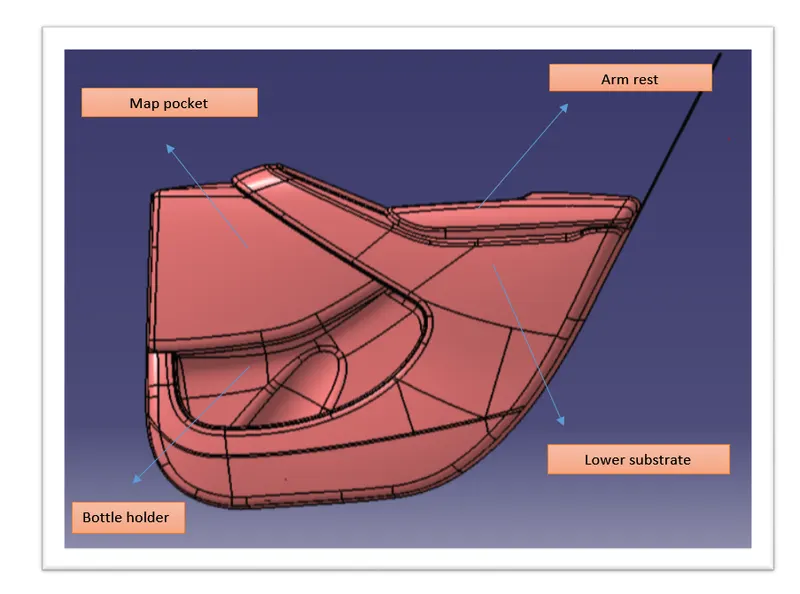
Engineering Attachment Features used in the door trim are:
- Heat stakes
- Locators
- Flanges
- Ribs
- Push Pin clip
workbench:
- Generative shape design
- Part design
- Assembly
Procedure:
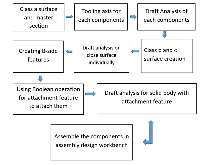
- Extraction of four components from a single profile of the door trim.
- Creating separate tooling axis for each components individually.
- Draft Analysis for all class a surface Inputs.
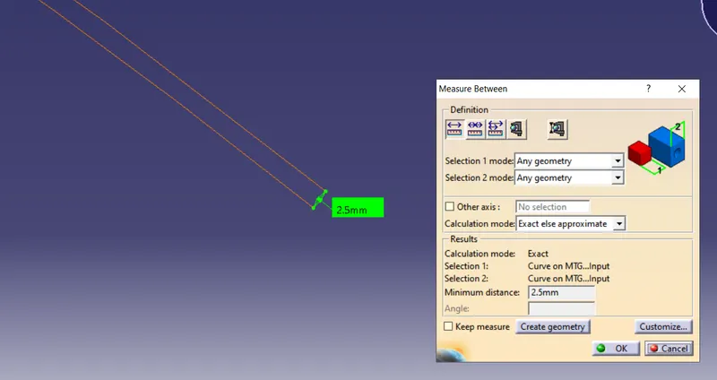
- Checking the measurements for nominal thickness from Master section.
- Creating class B and C surface for making it has solid body.
- Once more making a draft analysis for close surface of arm rest, map pocket, lower substrate, bottle holder.
- Again Taking the reference from master section for engineering attachment feature.
- creating attachment features like heat stakes, locators, flanges and ribs.
- Using boolean operation to attach the features in B-side of the door.
- After attaching the features the push pin clip is assemble to the respective dog houses.
- finally,the draft analysis is done on the solid body with attachment features with respect to draft angle.
Note: Draft analysis for the components are made according to recommended Draft angles.
Methodology :
1. Extraction of four components from a single profile of the door trim
- The input file has single geometrical set with all the surface of the class a door trim.
- creating a separate part for each extraction from the door trim.( i.e.arm rest, lower substrate, bottle holder, map pocket and push pin clip)
| Part No | Part Name | Class A surface |
| Part - 1 | Map Pocket |
|
| Part - 2 | Arm rest |
|
| Part - 3 | Bottle holder |
|
| Part - 4 | Lower substrate |
|
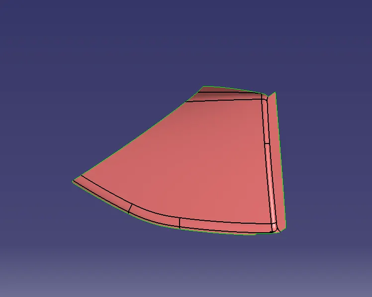
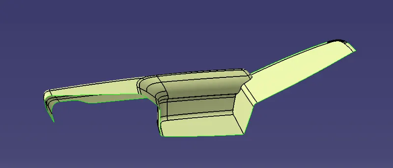
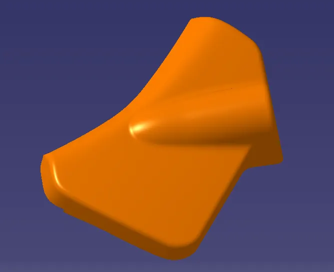
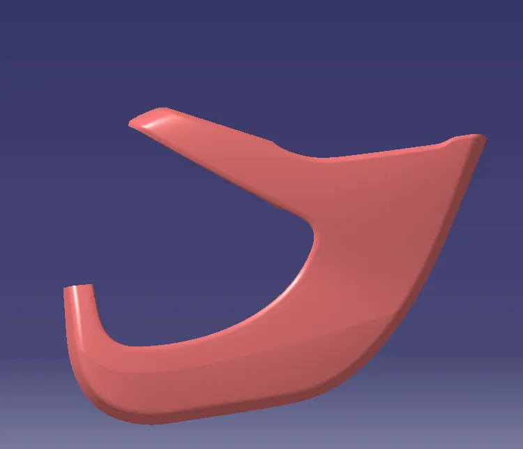
- collect the parts in a single assembly file and work on it separately. Name the assembly design as Final_door_trim_panel.
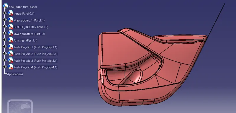
- Reference for part Nominal thickness from master section.
- Also reference for Engineering attachment features from master section.
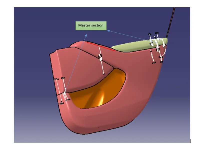
2. Creating separate tooling axis for each components individually.
- class a surface tooling axis for lower substrate direction along along y-axis.So it is easier for creating the heat stakes, locators and ribs.
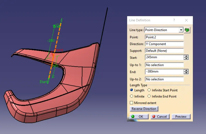
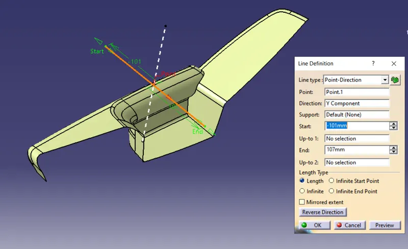
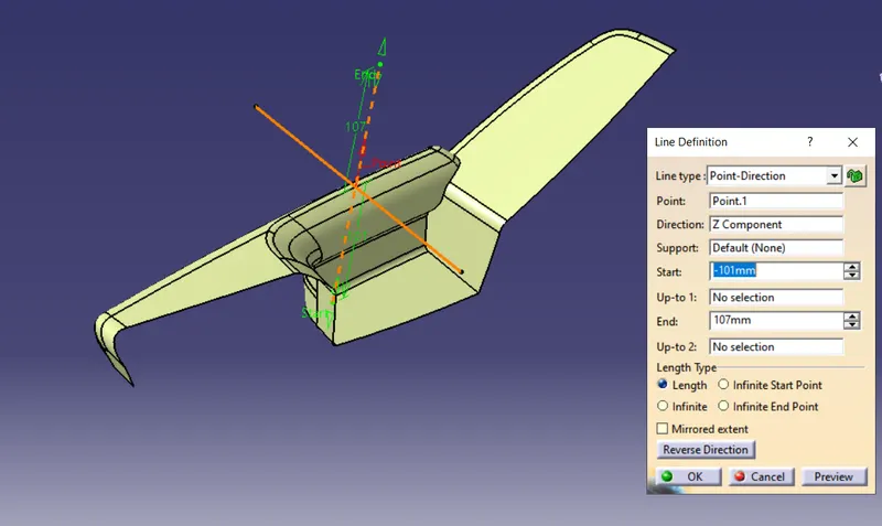
- class a surface tooling axis for arm rest direction along y-axis and z- axis. since the tooling axis along y direction doesn't clear the sides of the arm rest It requires side core. So there are two tooling axis for arm rest one is along y direction and other along the z direction.
1. Tooling axis along the y direction.
2. Tooling axis along the z direction.
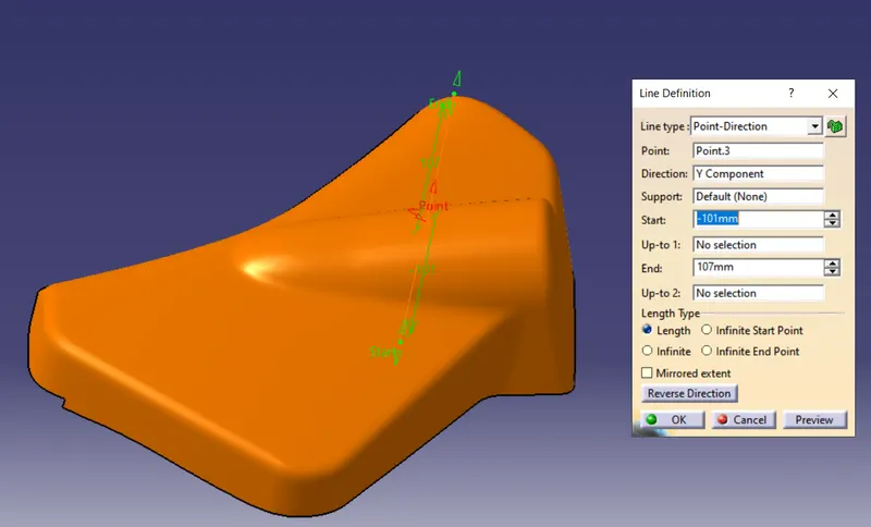
- creating a class a surface tooling axis for bottle holder along y direction.
- Class a surface for map pocket tooling axis along y direction.
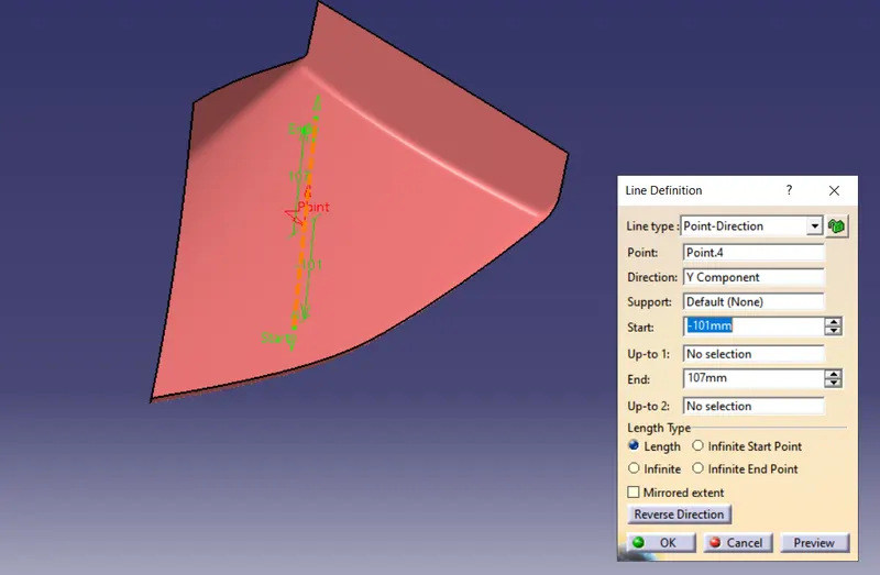
3. Draft Analysis for all class A surface Inputs.
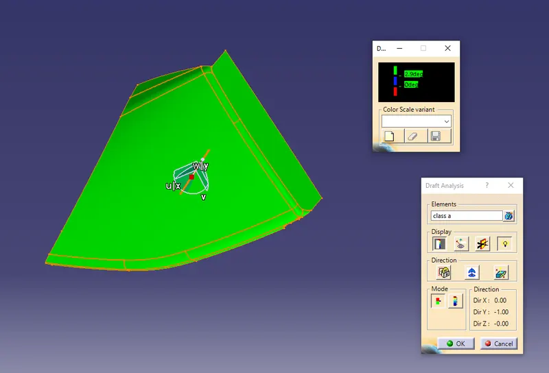
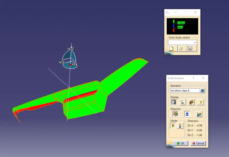
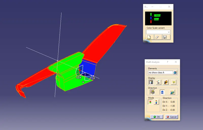
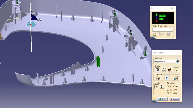
Draft analysis for the components are made according to recommended Draft angles
| color | value |
| Green | Above 3 degree |
| Blue | 0 degree |
| Red | below 0 degree |
| Part No | Part Name | Draft analysis |
| Part - 1 | Map Pocket |
|
| Part - 2 | Arm rest |
|
| Part - 3 | Bottle Holder |
|
| Part - 4 | Lower substrate |
|
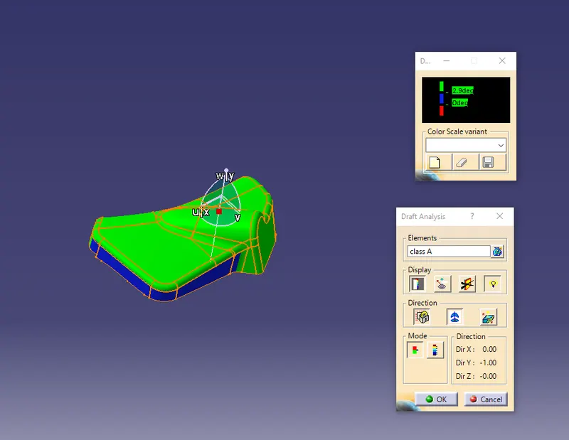
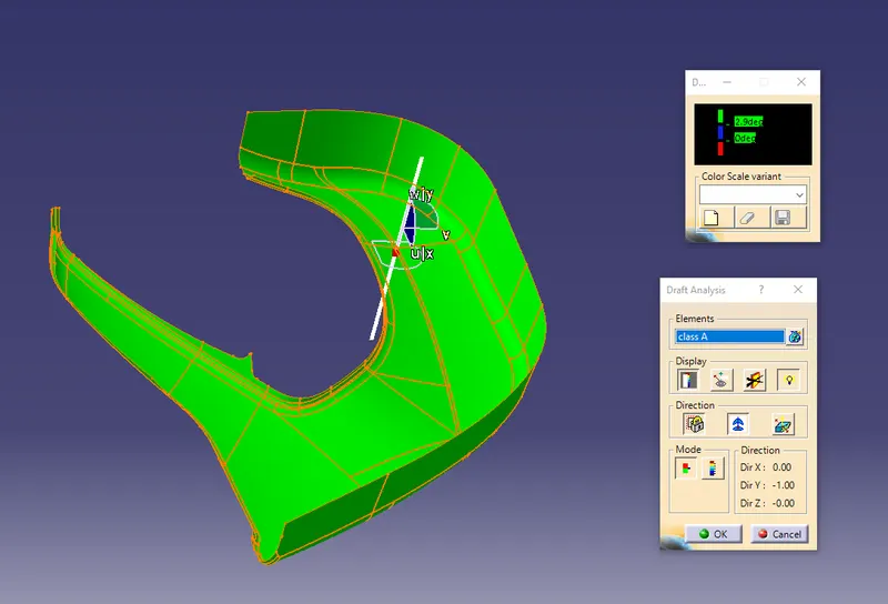
4. Checking the measurements for nominal thickness from Master section.
- Reference we acquired from the master section nominal thickness
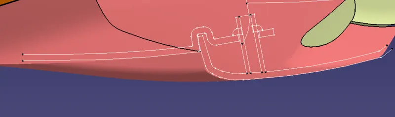
- Reference for engineering attachment feature.
5. Creating class B and C surface for making it has solid body.
Lower substrate:
Class B surface is created by offsetting the class A surface to 2.5 mm as our part nominal thickness is 2.5. but due to fillets some of the patches were not offset and they can be manually created using multi section surface option.
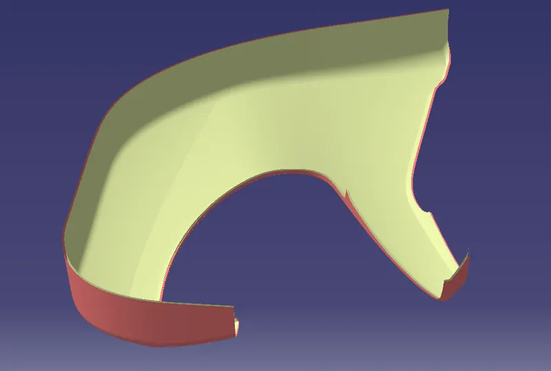
C surface is created by sweeping the outer edges of the Class A surface. In most of the areas 90 degrees of draft is maintained as the C surface is tooled with Class B surface.
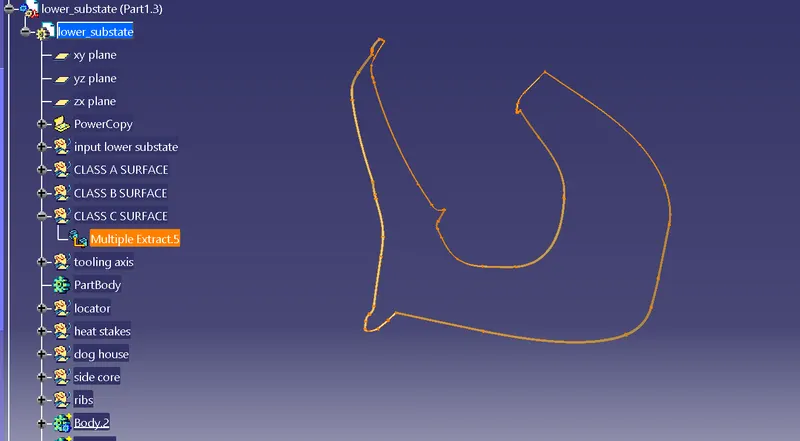
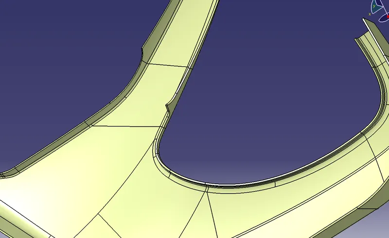
Trimmed surface of class a, b and c.
Door arm rest:
class b surface is created by offsetting the class a surface to 2.5 mm as our part nominal thickness. but in arm rest the fabrication is provide with the thickness of 2 mm. so the arm rest total thickness for creating class b surface is 4.5 mm.
Description
- fabrication thickness is 2mm
- under the fabrication there is a Non-shown class a surface we take into consideration and to work on it.
- for that we take part nominal thickness 2.5 mm. so total 4.5 mm.
Due to fillets some of the patches were not offset and they can be manually created using multi section surface option.
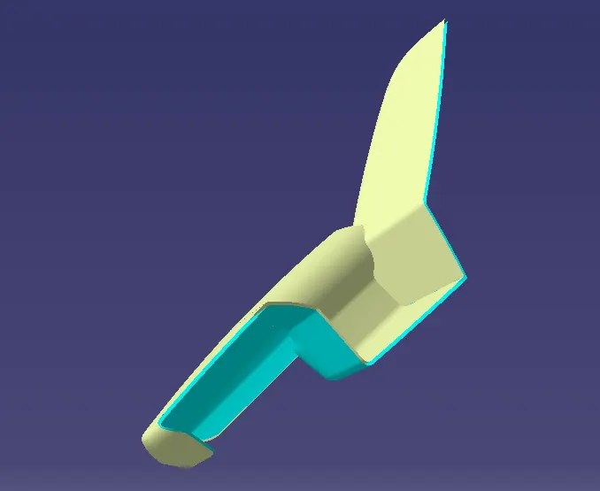
C surface is created by sweeping the outer edges of the Class A surface. In most of the areas 90 degrees of draft is maintained as the C surface is tooled with Class B surface. but some outer edges doesn't get sweeped .So consider 3 degree sweep along the tooling direction or reference surface for creating a close surface.
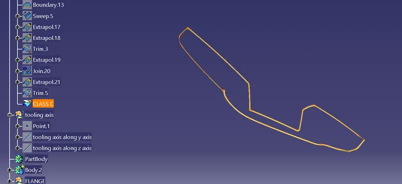
Trimmed surface of class a, b and c.
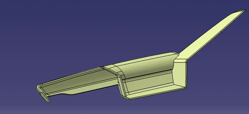
Map pocket:
Class B surface is created by offsetting the class A surface to 2.5 mm as our part nominal thickness is 2.5. but due to fillets some of the patches were not offset and they can be manually created using multi section surface option.
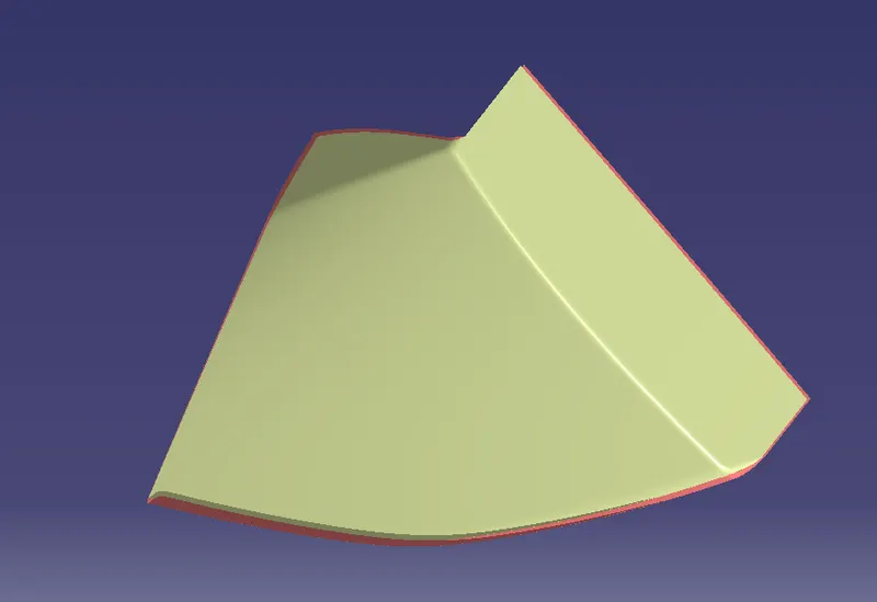
C surface is created by sweeping the outer edges of the Class A surface. In most of the areas 90 degrees of draft is maintained as the C surface is tooled with Class B surface.
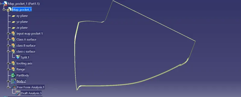
Trimmed surface of class a, b and c.

Bottle holder:
Class B surface is created by offsetting the class A surface to 2.5 mm as our part nominal thickness is 2.5. but due to fillets some of the patches were not offset and they can be manually created using multi section surface option.
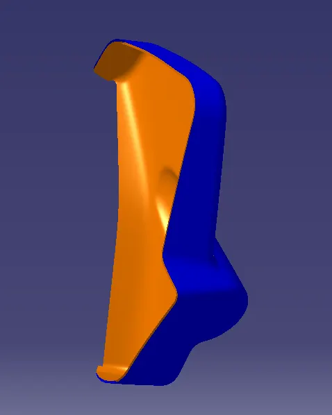
C surface is created by sweeping the outer edges of the Class A surface. In most of the areas 90 degrees of draft is maintained as the C surface is tooled with Class B surface.
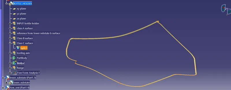
Trimmed surface of class a, b and c.
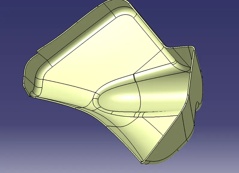
| Part No | Part Name | close surface |
| Part - 1 | Map pocket | 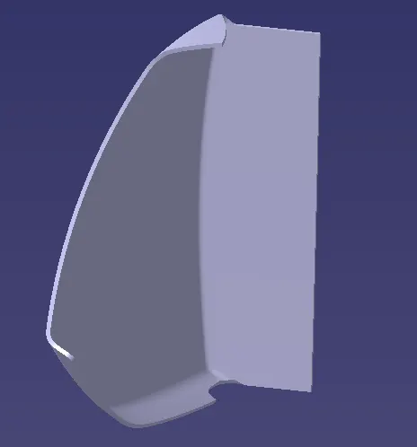 |
| Part - 2 | arm rest |
|
| Part - 3 | bottle holder |
|
| Part - 4 | Lower substrate |
|
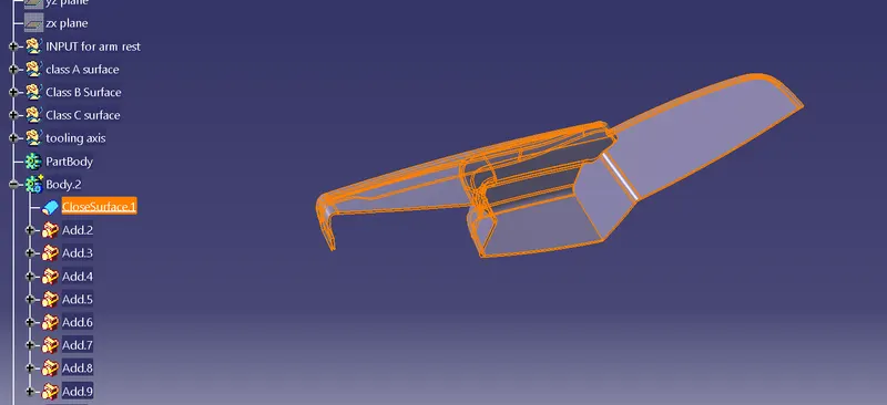
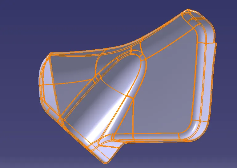
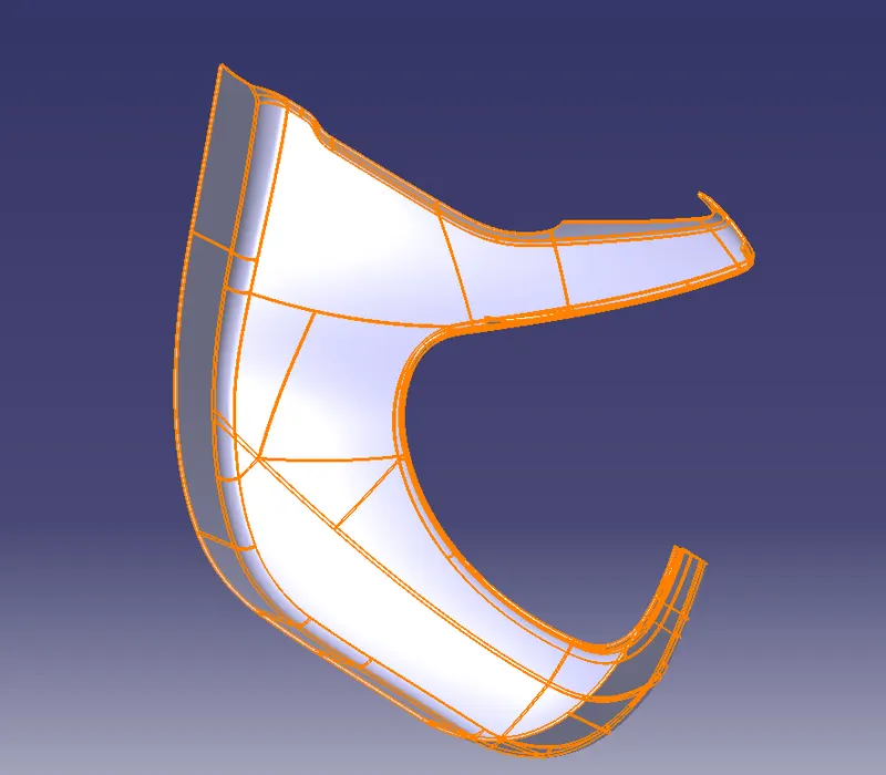
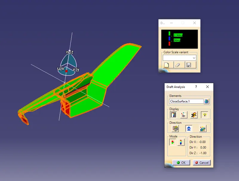
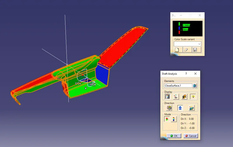
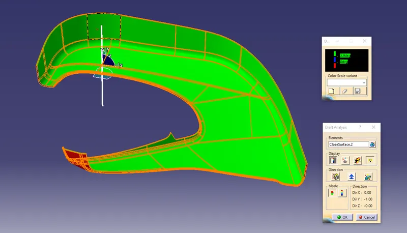
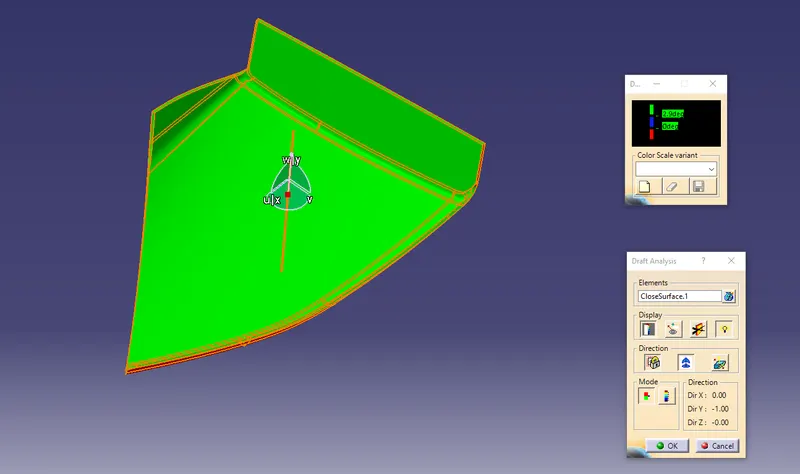
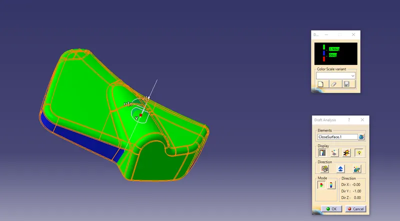
6. Draft analysis for close surface of arm rest, map pocket, lower substrate, bottle holder.
| Color | Value |
| Green | above 3 degree |
| Blue | 0 degree |
| Red | below 0 degree |
| Part No | Part Name | draft analysis |
| Part - 1 | Map pocket |
|
| Part - 2 | arm rest |
|
| Part - 3 | bottle holder |
|
| Part - 4 | lower substrate |
|
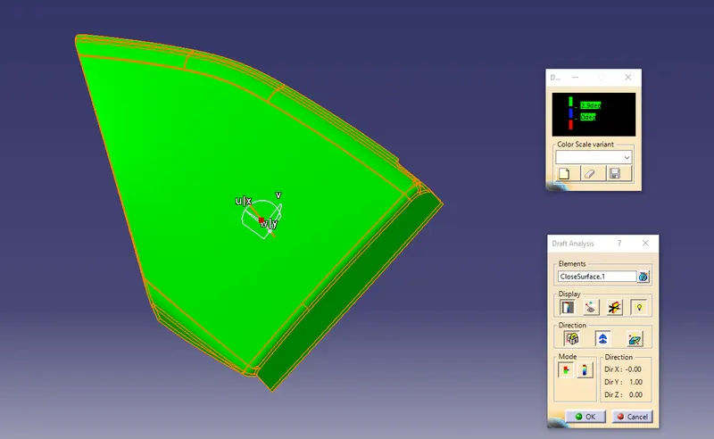
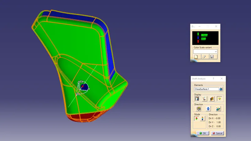
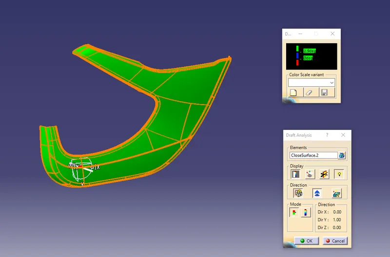
For clear Draft analysis view on close surfaces:
Arm Rest:
lower substrate:
Map pocket:
bottle holder :
7. Taking the reference from master section for engineering attachment feature.
- Reference like height for heat stakes, flanges and locators.
for example, take this image into consideration.
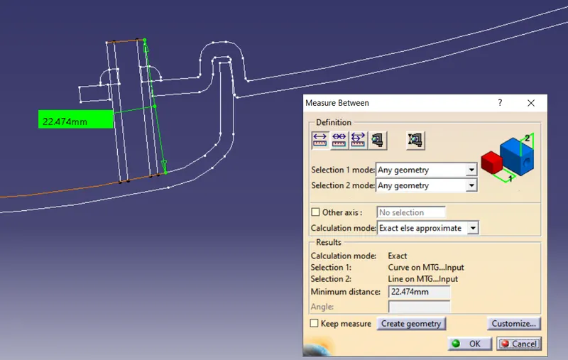
- height of the heat stakes from the surface of lower substrate.
- height of flange from the map pocket and lower substrate. these values are considered for creating them and attaching them.
8. creating attachment features like heat stakes, locators, flanges and ribs.
Heat stakes:
Thermoplastic staking, also known as heat staking, is the same process except that it uses heat to deform the plastic boss, instead of cold forming. A Plastic stud protruding from one component fits into a hole in the second component. The stud is then deformed through the softening of the plastic to form a head which mechanically locks the two components together. It is a versatile technique benefiting from being quick, economical and consistent. Unlike welding techniques, staking has the capacity to join plastics to other materials (e.g. Metal) in addition to joining like or dissimilar plastics, and it has the advantage over other mechanical joining methods in eliminating the need for consumables such as rivets and screw .
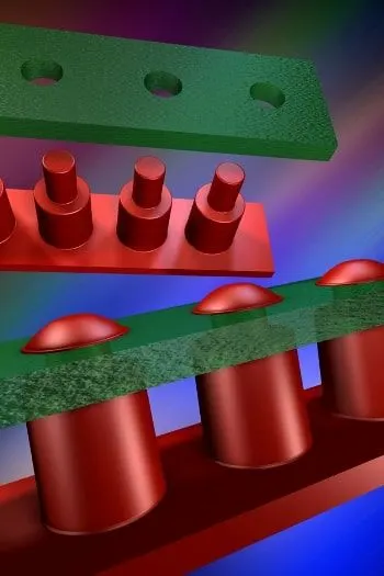
heat stake with ribs:
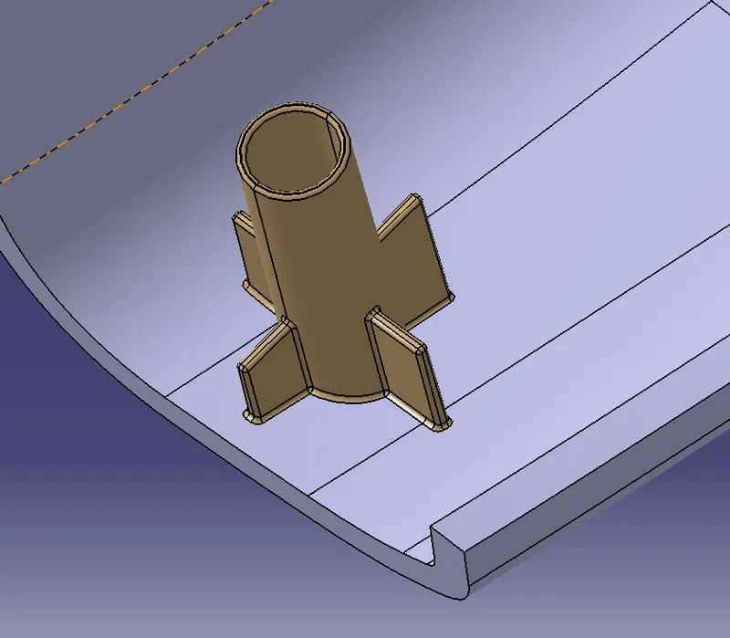
design and construction for heat stakes:
heat stakes diameter which is construction is depends upon the manufacturer. the diameter is altered in such a way that the sink marks are avoided and From the tip of the heat stake ribs and the flange is given with minimum 0.75 mm clearance for material to mold.
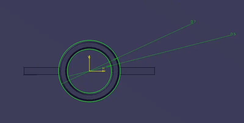
- so In this we consider diameter for heat stakes as outer 7mm and inner 5mm.
- also the clearance from the tip of the ribs to the flange diameter is 0.75 mm.
- the height of ribs are extracted from the master section.
Firstly, the following the outer and inner dia is given to the heat stakes.
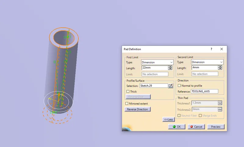
In part design, use pad to create the heat stakes with more option.
Draft for heat stakes:
For drafting the heat stakes we gave 0.5 deg .so that it gets clear for draft analysis.
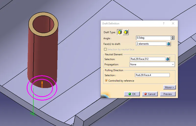
After drafting adding ribs to it.
sketches for ribs:
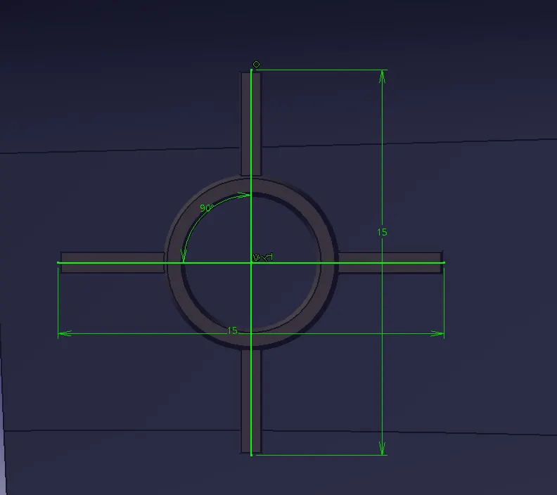
In Part design, pad the sketch for ribs.
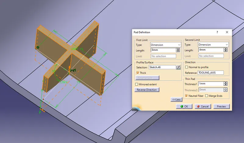
After creating ,use boolean operation union trim to combine both the ribs and heat stakes.
Draft angle is given the ribs:
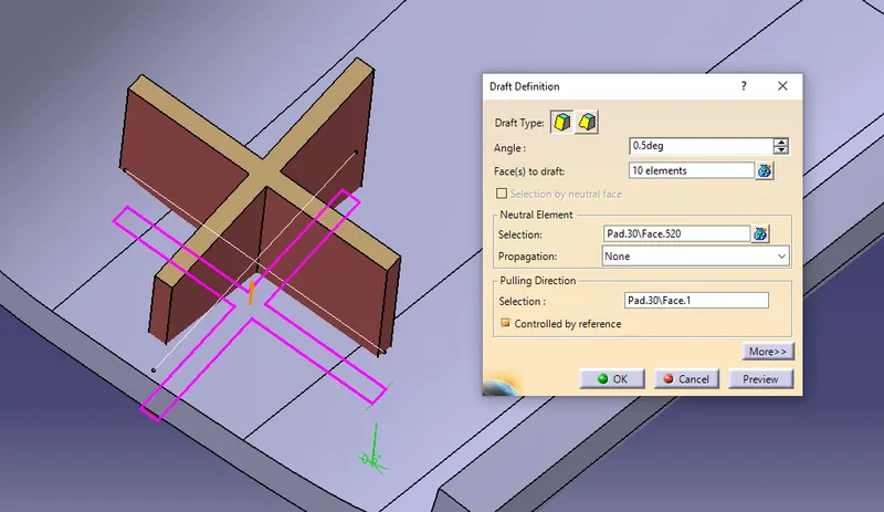
using boolean operation the combine the ribs and heat stakes.
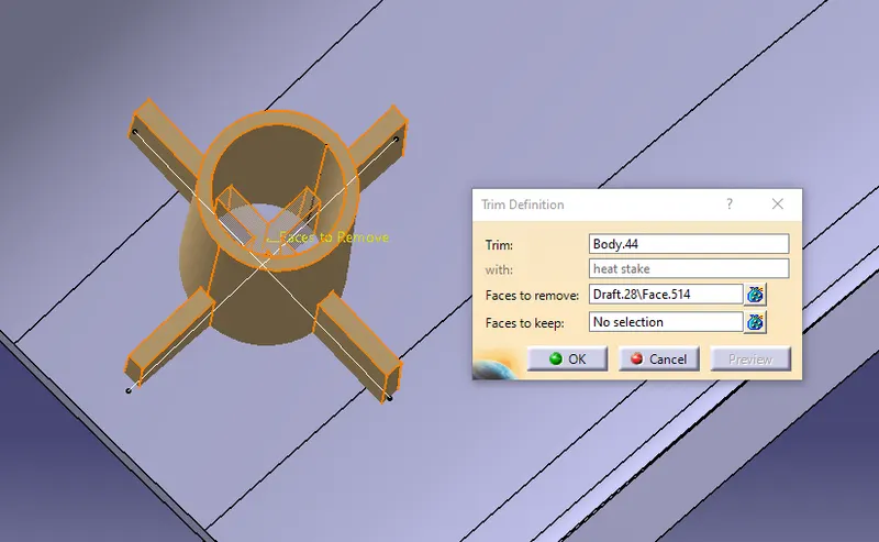
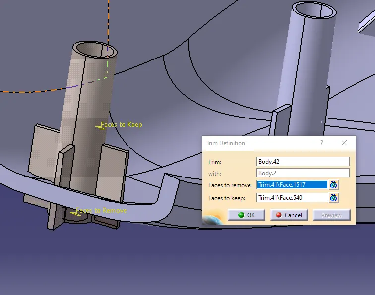
after designing the ribs with heat stakes. attach them to lower substrate. using boolean operation union trim to join the heat stakes to the lower substrate.
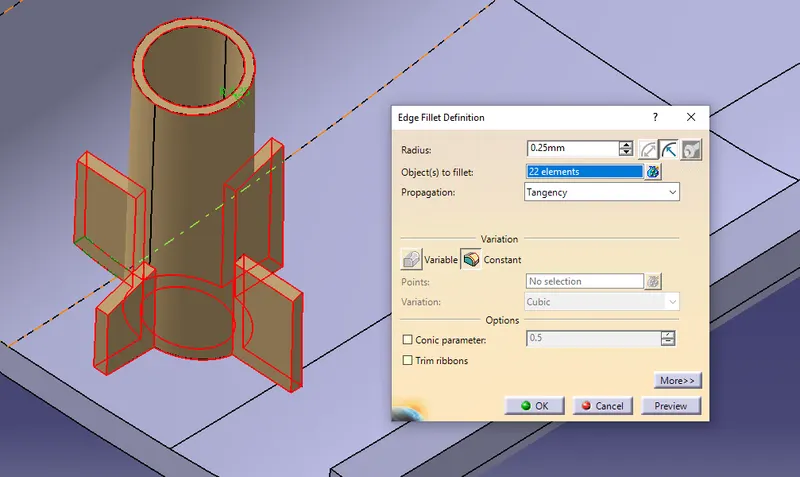
Giving fillets for the heat stakes.
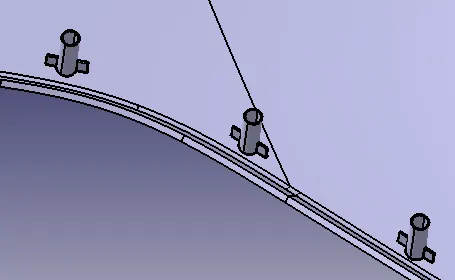
same procedure is taken for all the heat stakes with using the option call power copy.
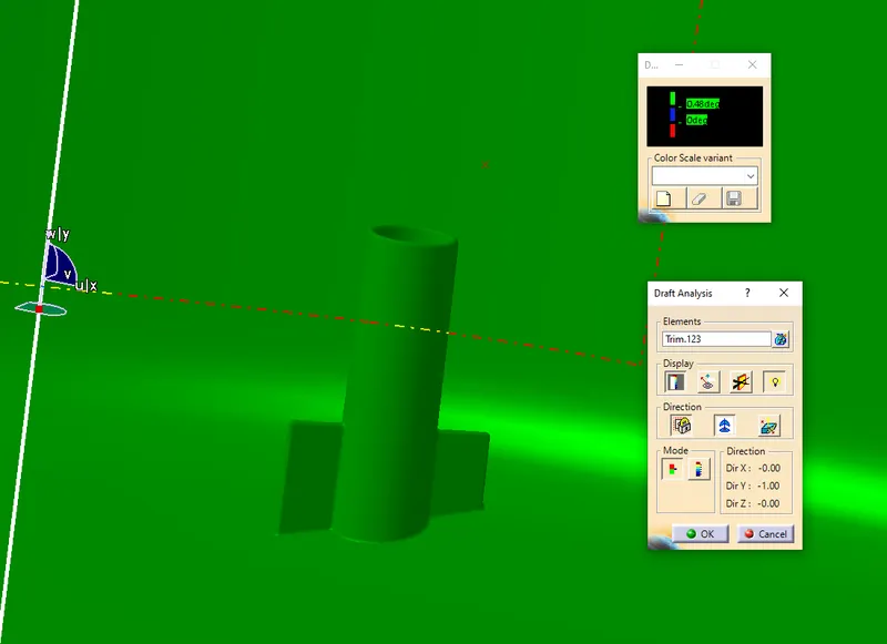
Draft analysis for the heat stakes.
Locators:
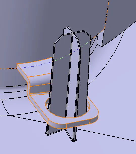
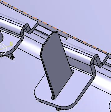
Locators are provided for arresting the motion the part during heat staking.In the model there are two types of locators are used to arrest the motion which are 4- way and 2- way locator. 4-way locator means you prevent movement at 2 axis (+X, -X, +Y and -Y) on the plane. 2-way mean you prevent movement only at 1 axis on the plane.
4-way locator:
2-way locator:
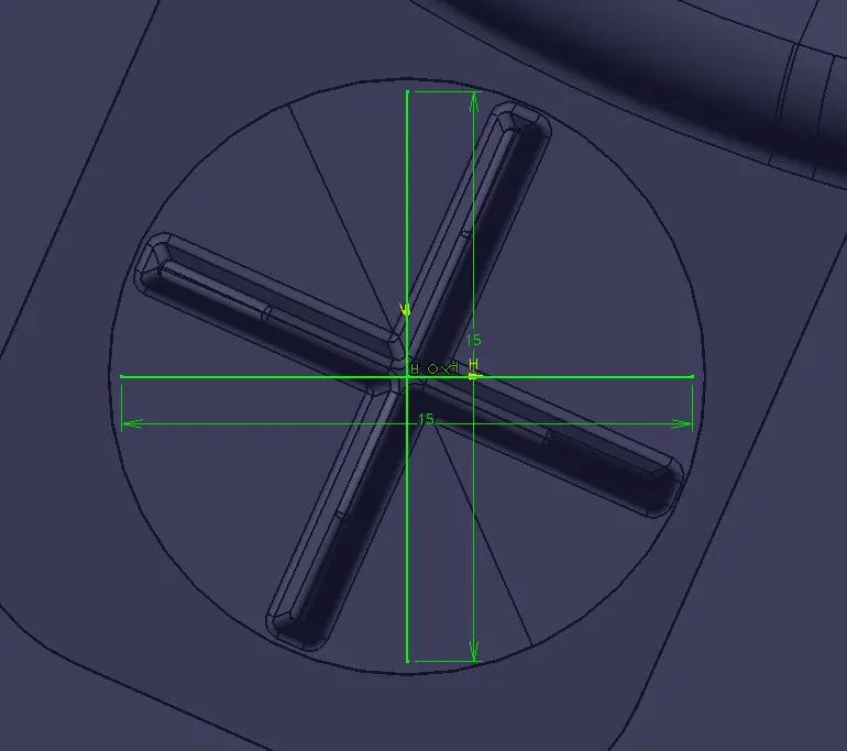
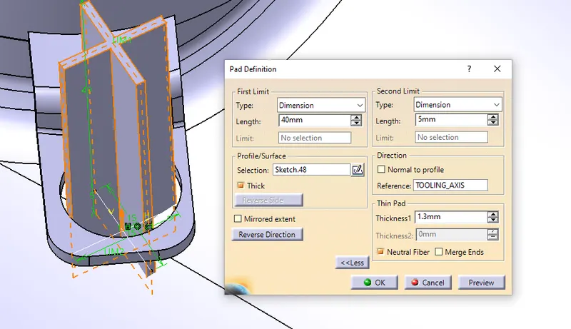
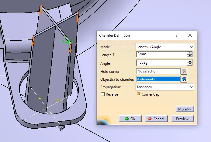
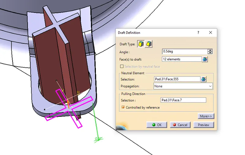
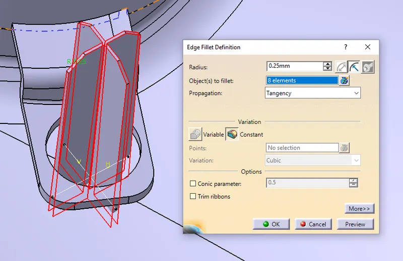
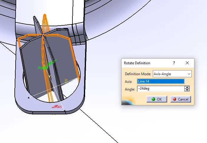
procedure for creating 4-way locator:
step 1: sketch
step 2: pad
step 3: chamfer
step 4: Draft
step 5: Fillets
step 6: rotate
draft analysis on locator:
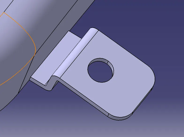
Flanges:
flange is a mounting feature for fixing the components together .flange with a hole cut out for thermal staking and This helps the other to attach them with the base lower substrate.
creation of flange:
step 1: extraction from the edge of the class b surface by using extract option in GSD.
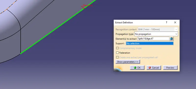
step 2: sweep along y-direction or use reference surface to sweep the extracted element.
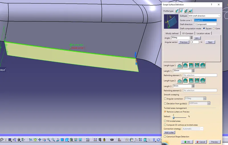
adjusting the angle of sweep to get the height of the flange
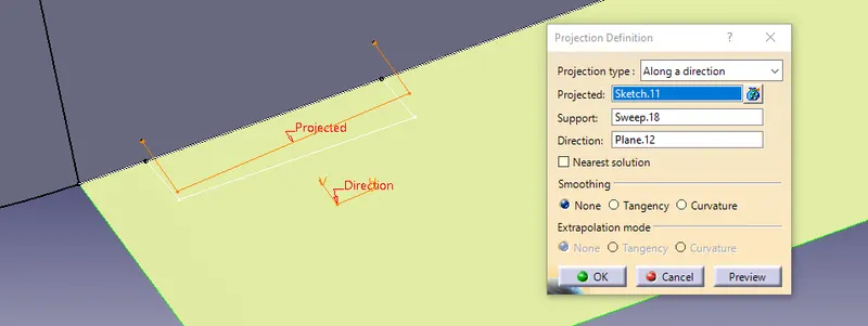
step 3: sketch and projection
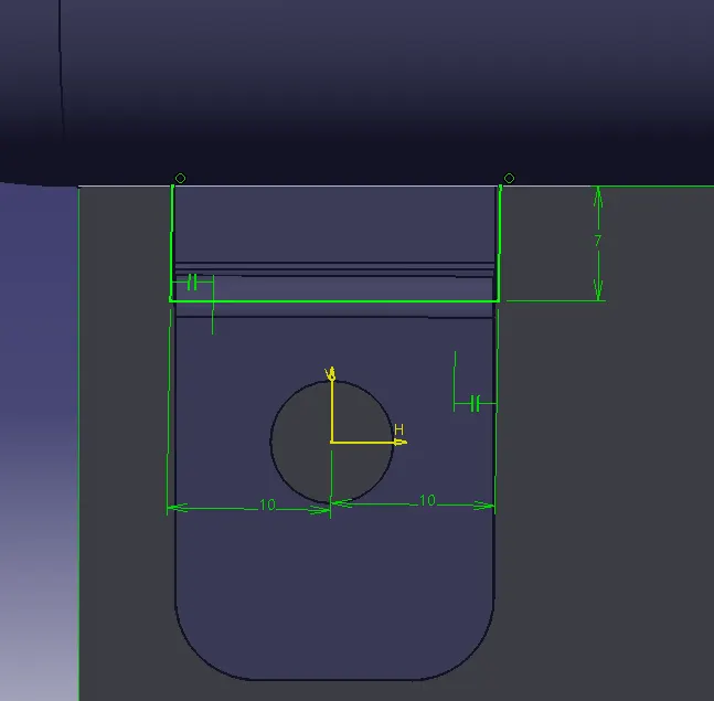
after sketching the flange base project option is used for projecting the sketch on sweep that we created.
splitting the projected sketch from the sweep
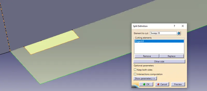
step 4: sweeping the edge of the split sweep with the angle of 3 degree.
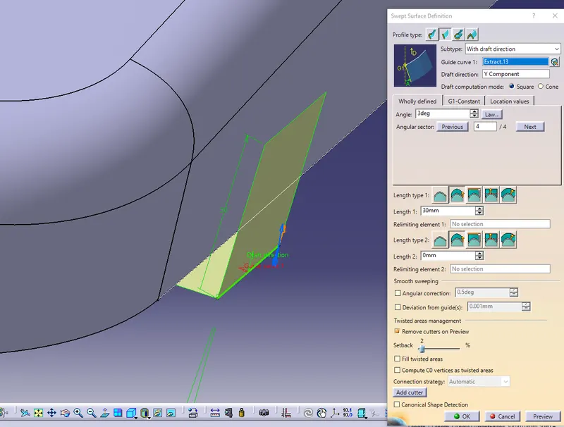
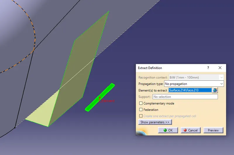
step 5: extract the surface from the heat stake ribs.
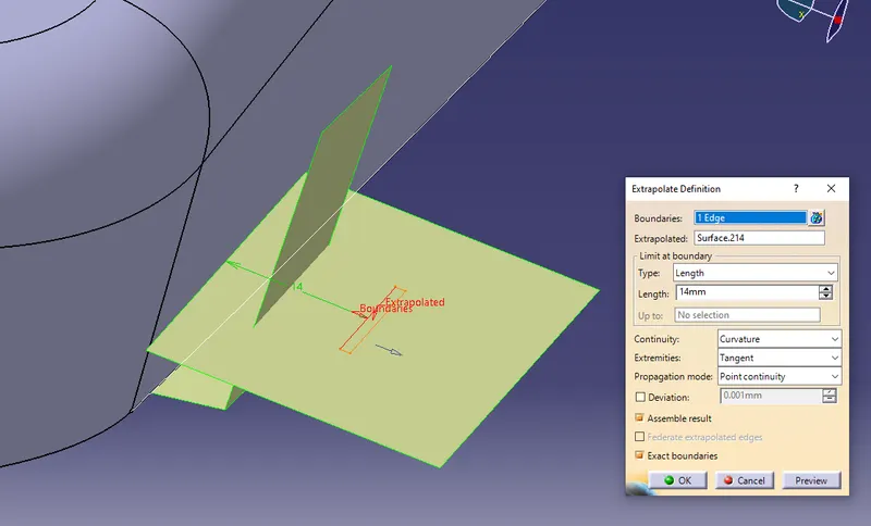
step 6: extrapolate the extracted surface.
step 7: trim the surface and give fillets.
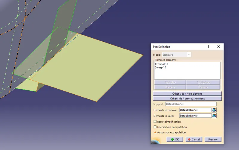
join the trimmed surface with split sweep.
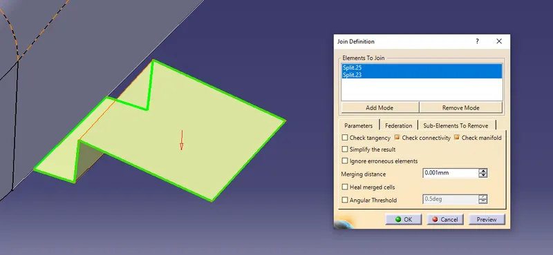
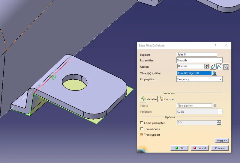
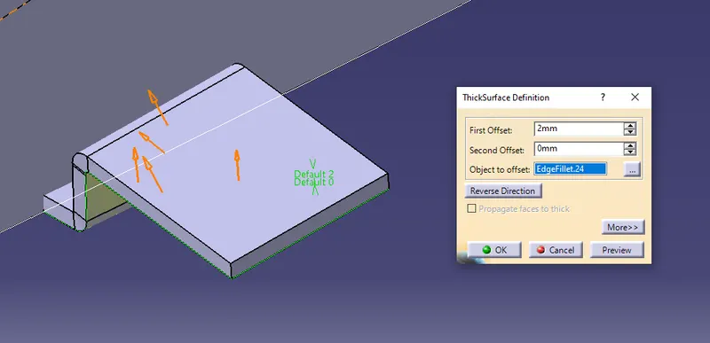
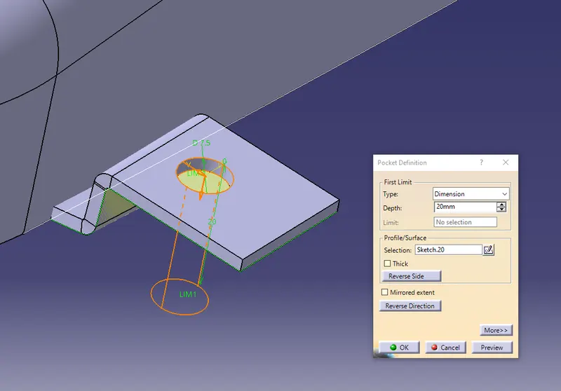
step 8: thickness, hole cut out, draft and fillets.
thickness:
Hole cut out:
draft for the sides of the flange:
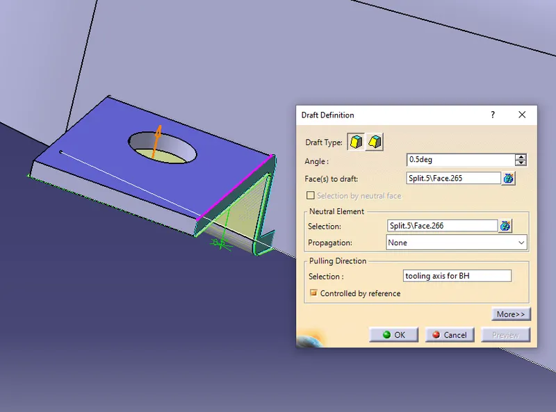
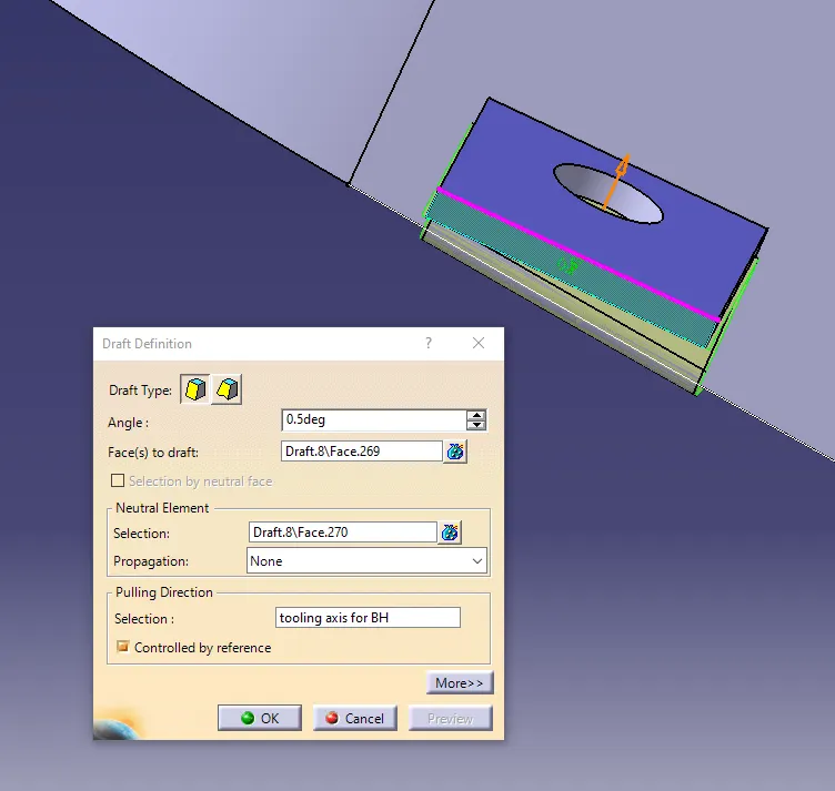
fillets:
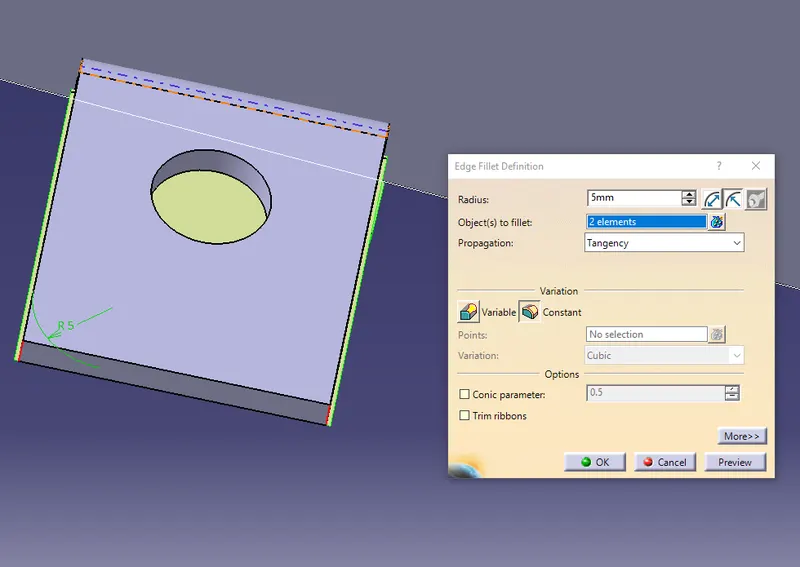
some procedure is followed for all the flange created in the components.
Draft analysis on flanges:
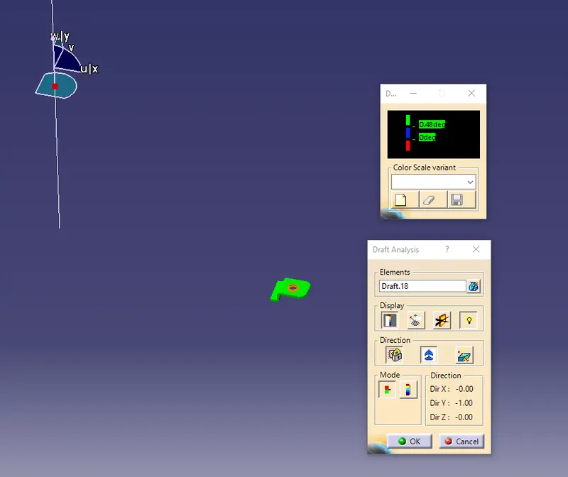
DOG HOUSE:
The Dog House is Created for mounting the push pin clip. the height of the dog house is high so providing the stability by creating ribs on the sides of the dog house.
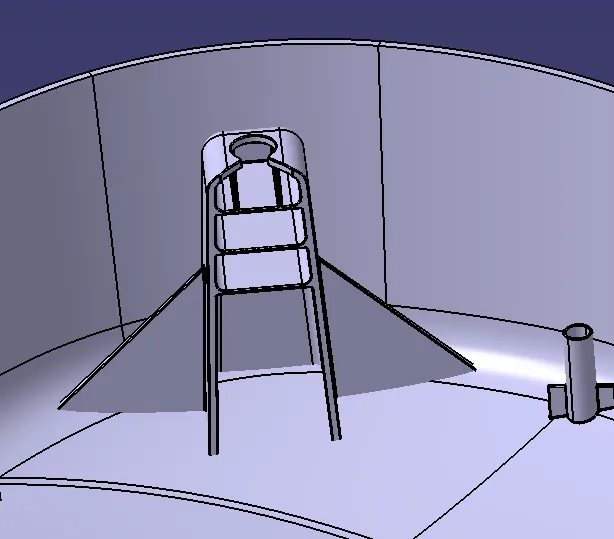
Dog house is an engineering feature used in the plastic trim design. The primary function of a dog house is to avoid sink marks on the class A surface which may occur due to features such as a locator or rib on the backside of Class So the best possible solution is to increase the height and give a support to obtain the position.
Design rulers for dog house:
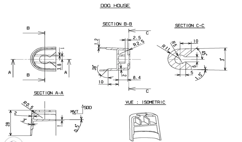
Creation of the Dog house:
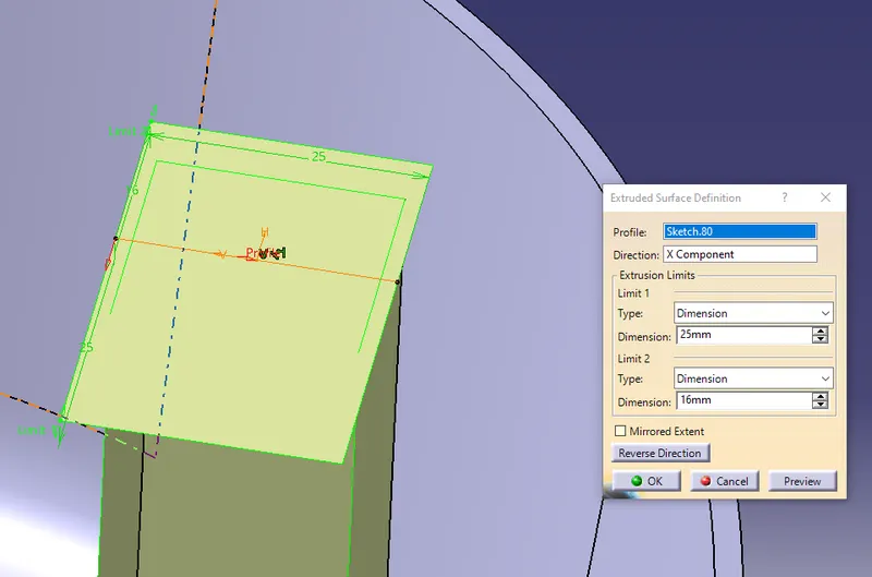
step 1: creating the sides of the dog house in the in GSD with a sketch and extrude option.
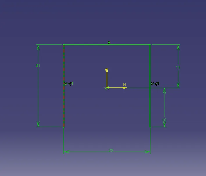
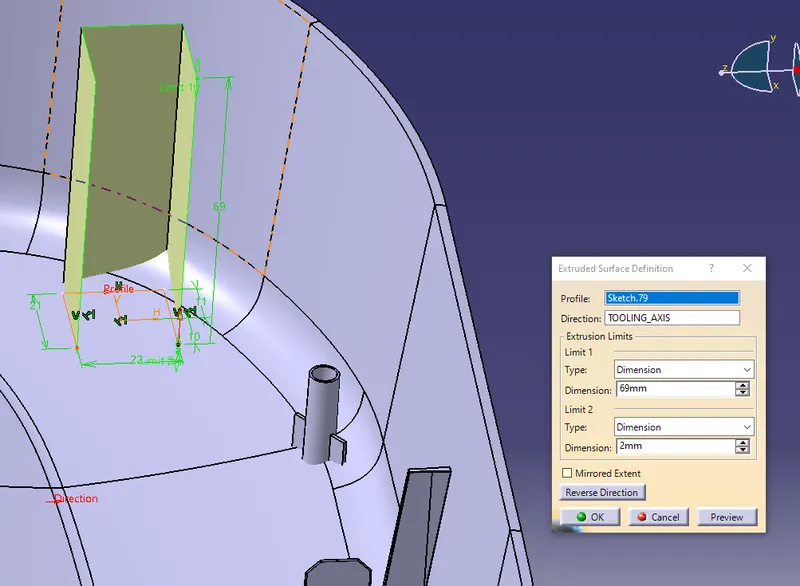
step 2: creating a plane and closing the roof of the dog house with same extrude option.
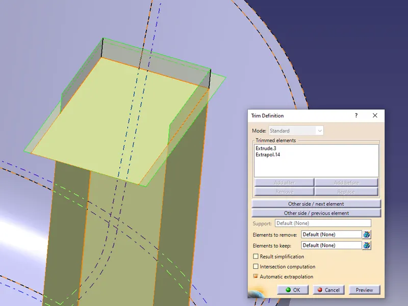
trim and split it with bottom extrude.
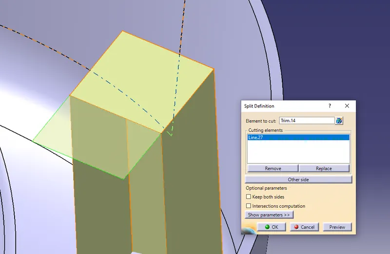
now split to form house.
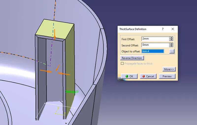
step 3: creating the solid body for the closed house using thickness option.
for creating slabs and inside the dog house same extrude feature is used again.
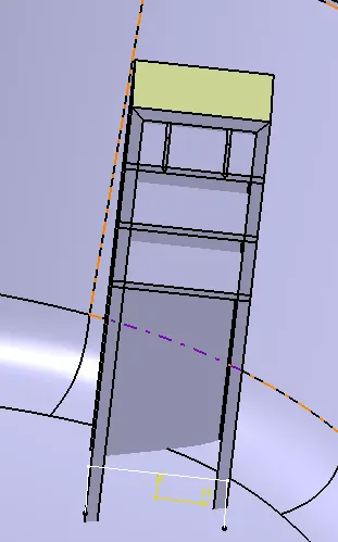
step 4: using the boolean operations like remove and union trim the required dog house material is produced.
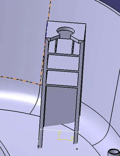
for the roof cut out I used sketch and remove boolean option to get the required shape.
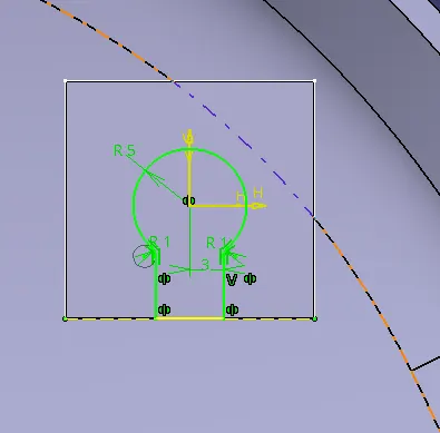
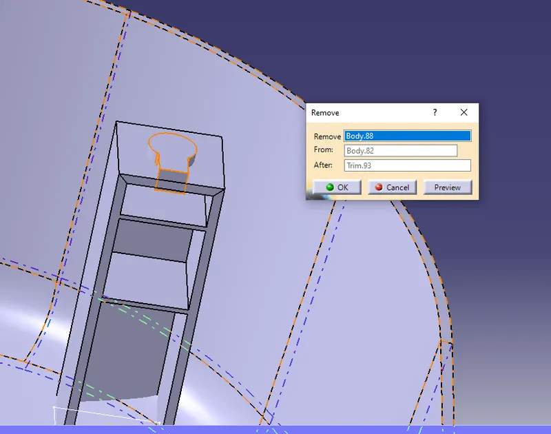
step 5: rotate the body towards tooling axis and parallel to lower substrate to attach the features.
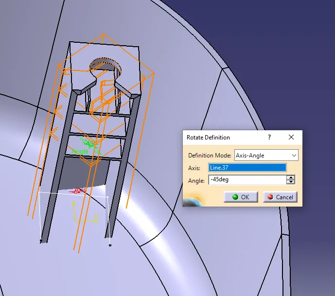
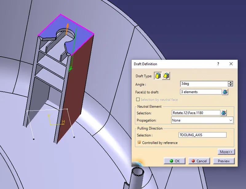
step 6: draft angle for outer and inner core, slabs and ribs.
Draft angle of 3 degree given to the outer sides of the dog house along the roof of the dog house as neutral element.
Draft angle of 3 degree given to the inner sides of the dog house along same roof as neutral element.
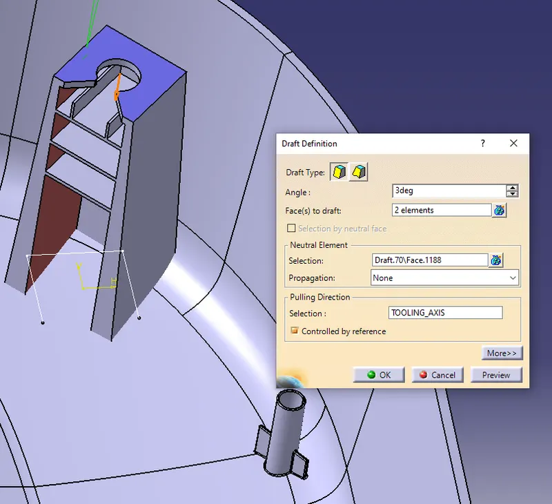
After the giving the dog house draft. certain element cannot be clear in main tooling axis. so we require side core with separate tooling axis for each dog house.
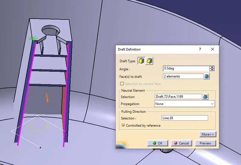
draft angle 0.5 degree for slabs and ribs.
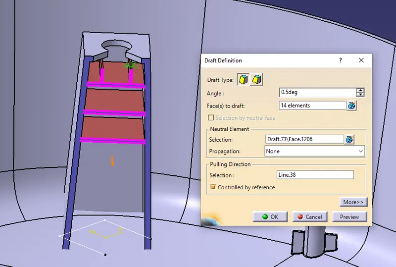
for clearing the draft on front side of the dog house. we consider neutral element as roof of the dog house.
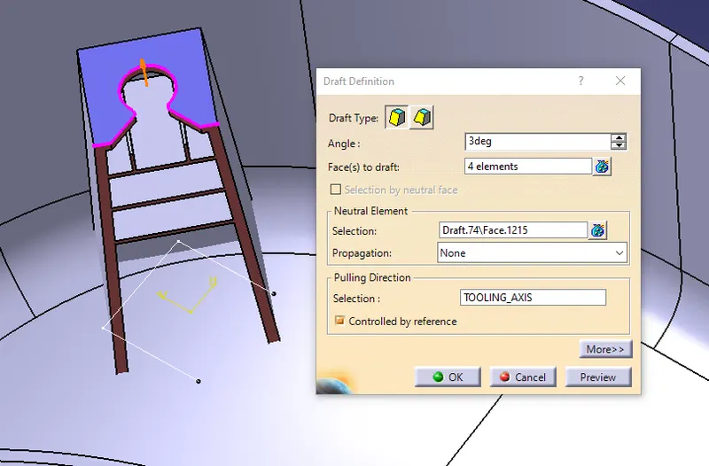
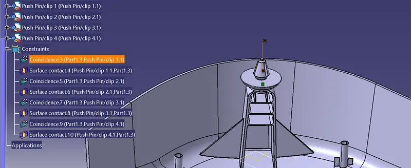
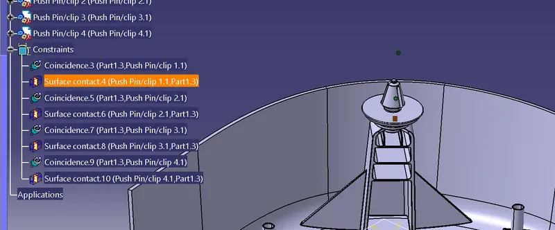
finally, ribs are provided for the dog and push pin clip is assembled with the dog house roof using assembly design.
corresponding fillets are provided using edge fillet.
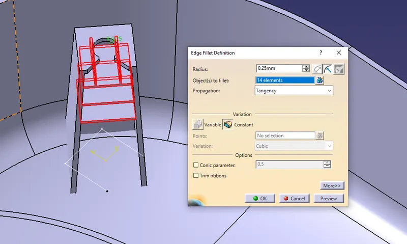
ribs for the sides of the dog house is union trimmed with dog house and again union trimmed with lower substrate as attachment feature.
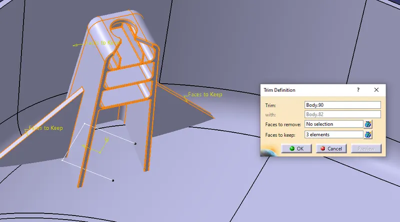
In Assembly design the push pin clip in constrained using option like coincidence, surface contact and others.
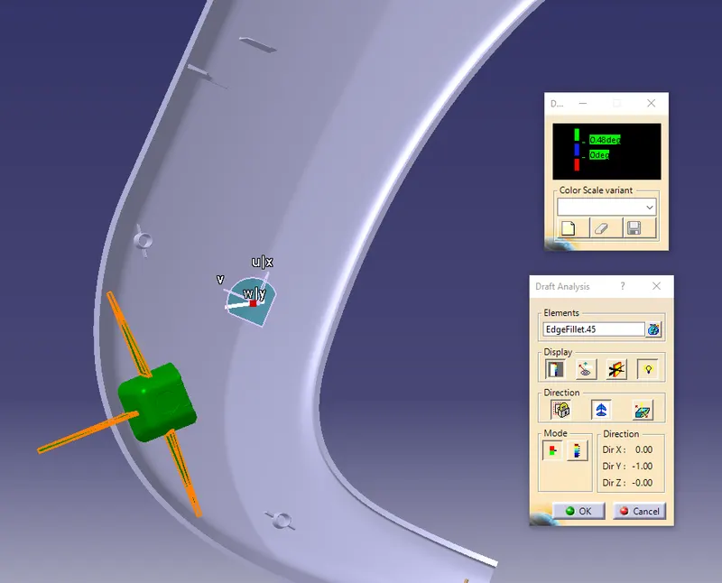
Draft analysis on the dog house with main and side tooling axis:
draft analysis along side core tooling axis:
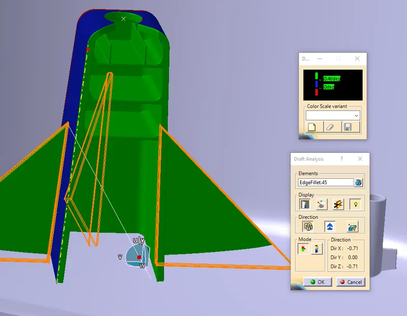
draft analysis on dog house in main tooling axis:
push pin clip:
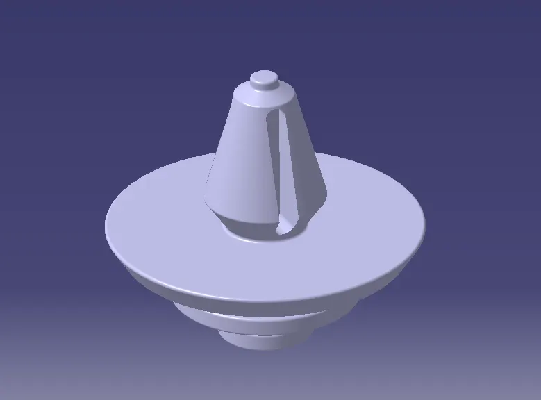
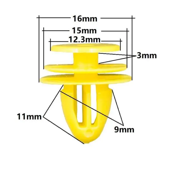
Push pin clip is inserted into the dog house roof where slots are provided for the clips to install. locking feature on the dog house to stop the movement of the clip and attach them with the required constrain.
Draft analysis on final parts:
part -1 Map pocket:
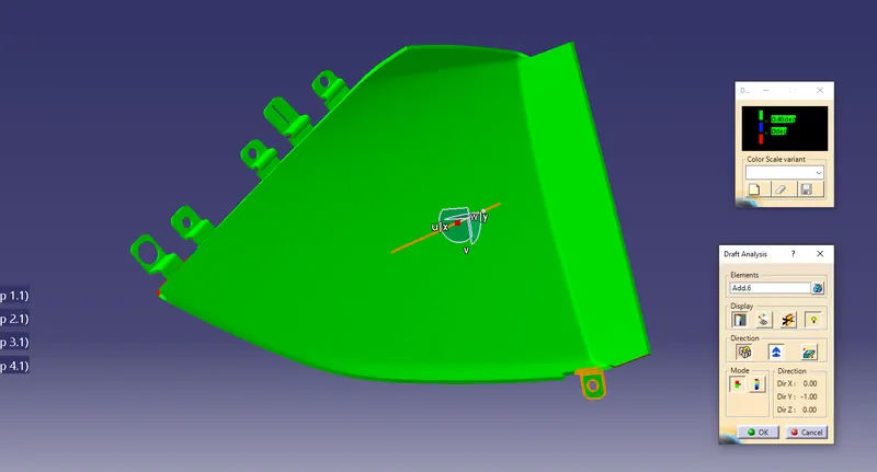
part -2 arm rest:
main tooling axis:
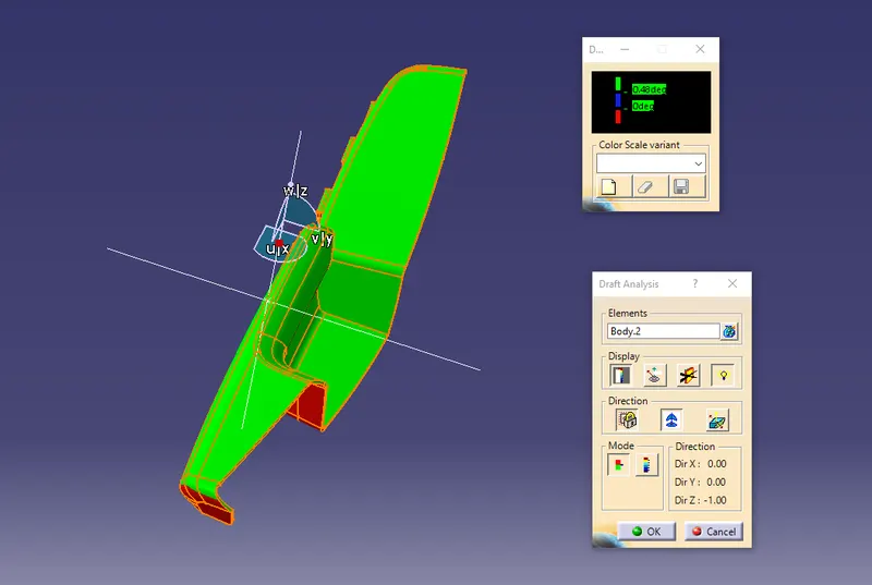
side core tooling axis:
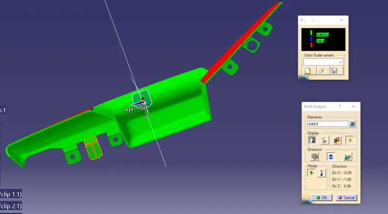
part - 3 bottle holder:
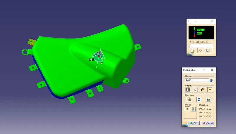
part - 4 lower substrate:
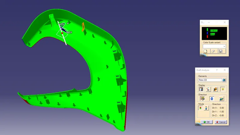
final product: