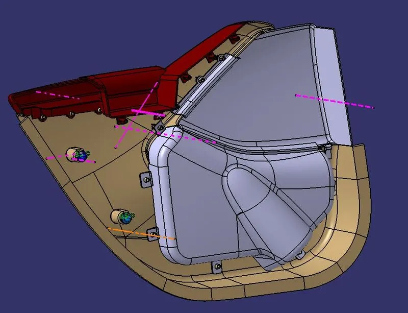
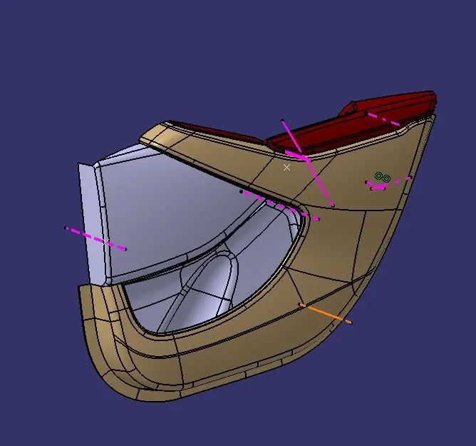
Week 11 - Final project
AIM : To creation a CAD model ,considering Nominal thickness and Mastersections.
OBJECTIVE :
- Creation of CAd model ,considering NOmianl Thickenss and Attacment Strategy.
- Create thickened part using master section for reference
- Create the mounting features as per design guidelines in the industry and with master sections
- Apply material details
- Draft analysis & Tooling analysis
INTRODUCTION :
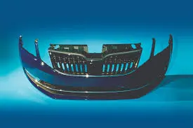
NEW PLASTIC PRODUCT DEVELOPMENT : This is one of the stage in the product life cyle , in this stage the major work of the design done by taking inputs from the class A designers and work on those inputs to create the CAd model. This CAD model is created by using CATIA V5 softwares. IN this stage the class A is divided into sub parts and made them into workable .
Example : Designing the surafce of a front bumper model from the class A surafce and made them into manufacture.
PROCEDURE :
1.Import the file : File>open>browse file and selct file :MAtersection Development.igs. ( fig 1.1)
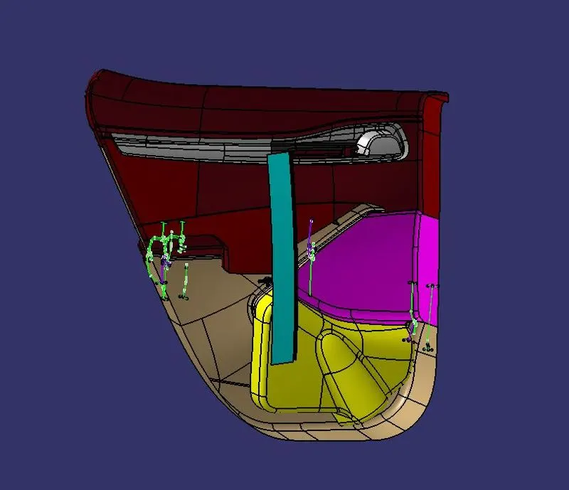
figure 1.1
2. Class A model Modification as per the mastersections : From the given input we have to do a CAD model of Lower subtrate ,Map pocket and Door arm rest.
A. Map pocket : From the given class A the map pocket is divided into 2 parts and worked on that parts. By using the master sections the class a is modified.
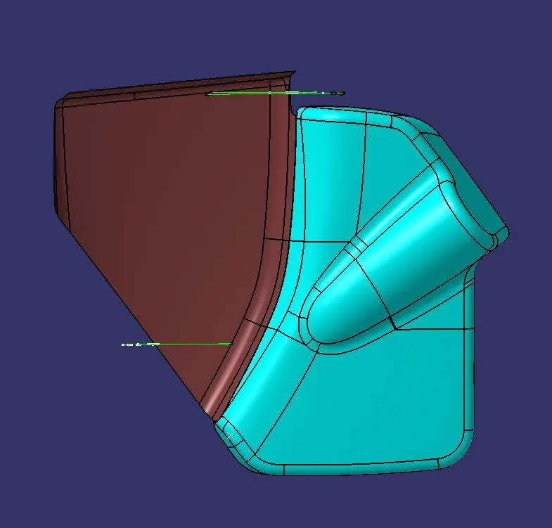
GIVEN CLASS A
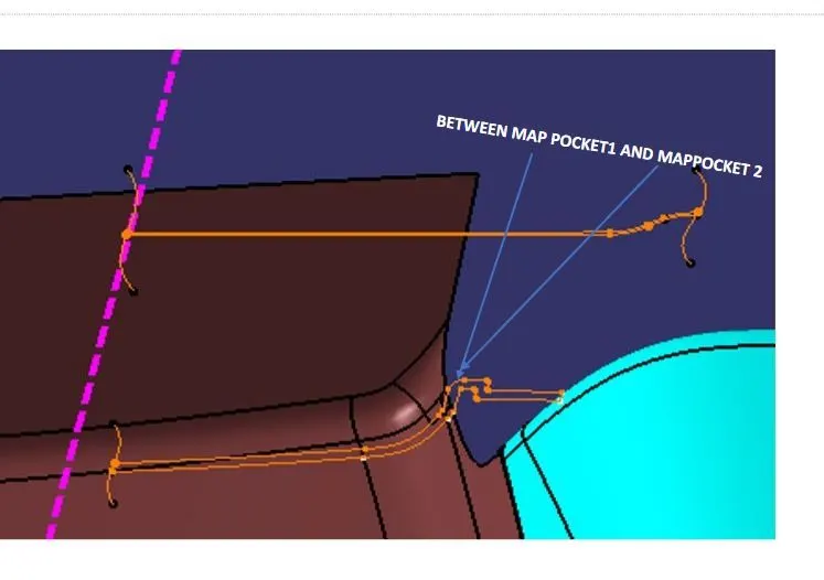
MATERSECTION
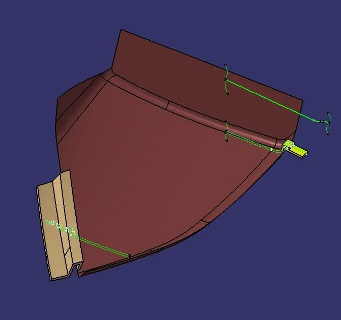
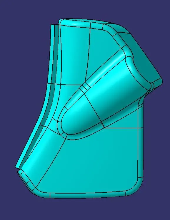
Dveloped map pocket 1 Developed mappocket 2
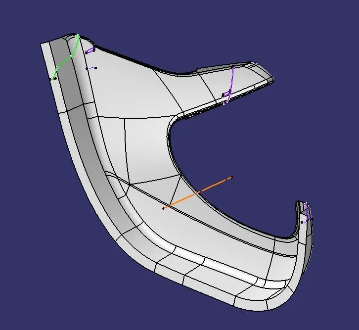
B. Lower Subtrate : By taking mastersections as a input the lower subtrate is modified .There are three ppositions where the class A of lower subtrate is modified.
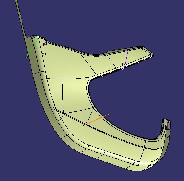
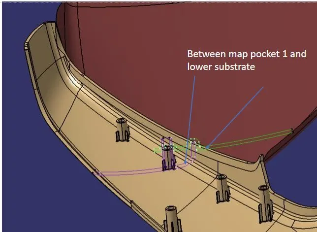
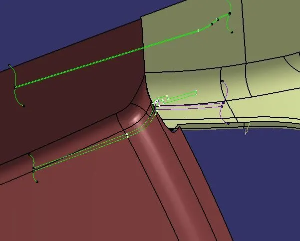
Given class A Mastersections between mapocket and lower substrate
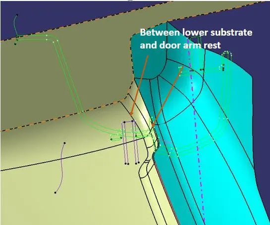
Modified class A Final class A
C.Doorarm Rest : According to the mastersection the class A of the doorarm rest is divided into 2 parts and modified .
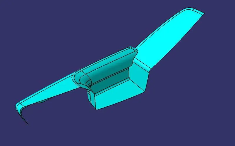
Door arm rest
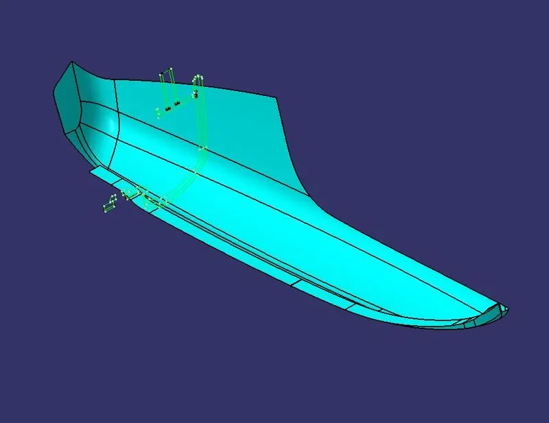
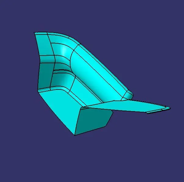
Modified Class A of Door arm rest
3. Finding the Tooling direction: All the parts except the door arm rest satisfied the global Y tooling direction. The tooling direction for the Door arm rest Part 2 is taken from the compass direction. Because it is not satisfying the global Y direction.
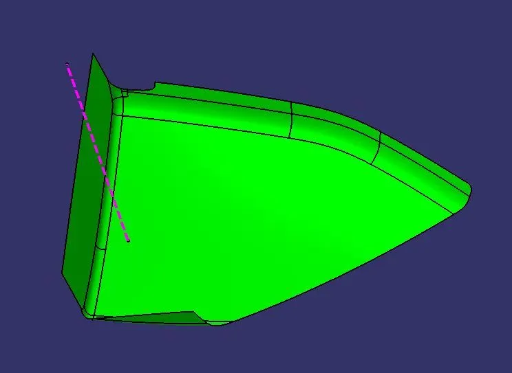
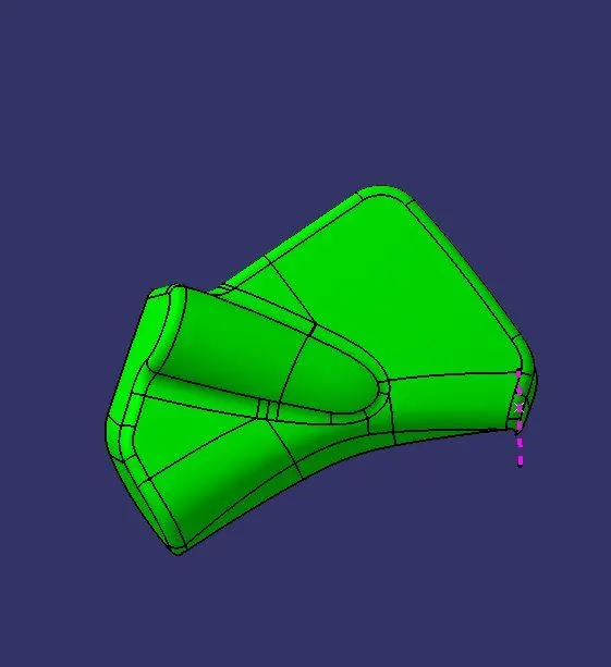
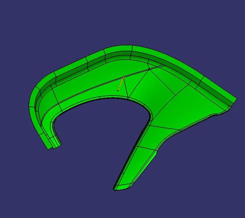
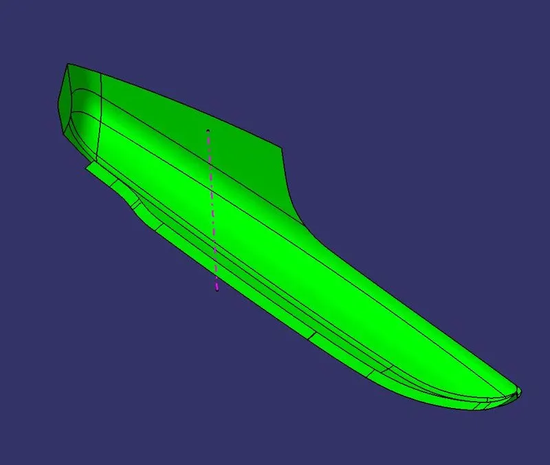
Map pocket 1 Map pocket 2 Lower substrate Door arm rest 1
Tooling Direction Satisfied in Global Y direction for Above parts
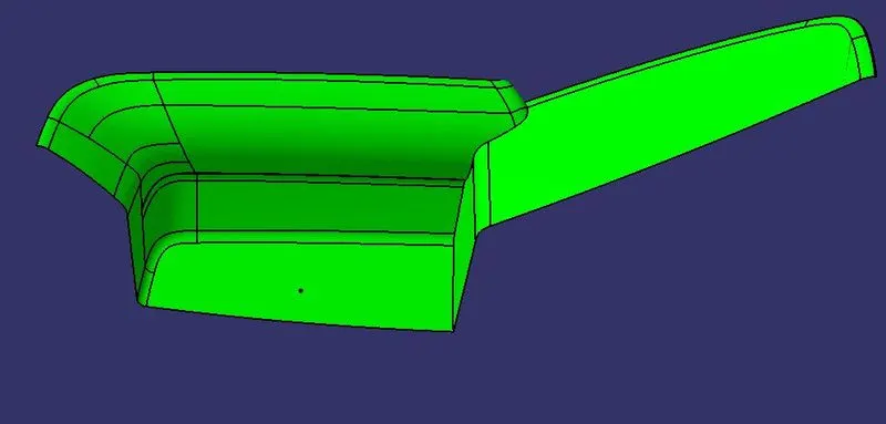
Compass Tooling Direction Has been taken
4. Class B sufaces : Class B surafes are created by offsetting the Class A surfaces to 2.5mm. And if any modifications like extrapolations ,splits are done on the CAlss B surfaces to meet the requirements.
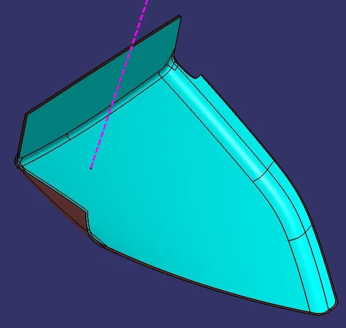
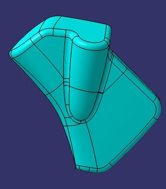
Map pocket 1 Map pocket 2
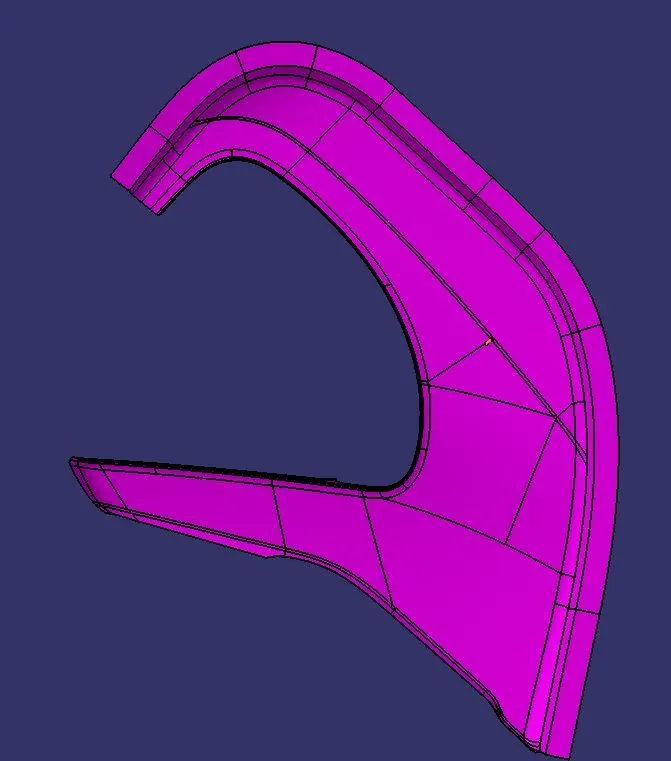
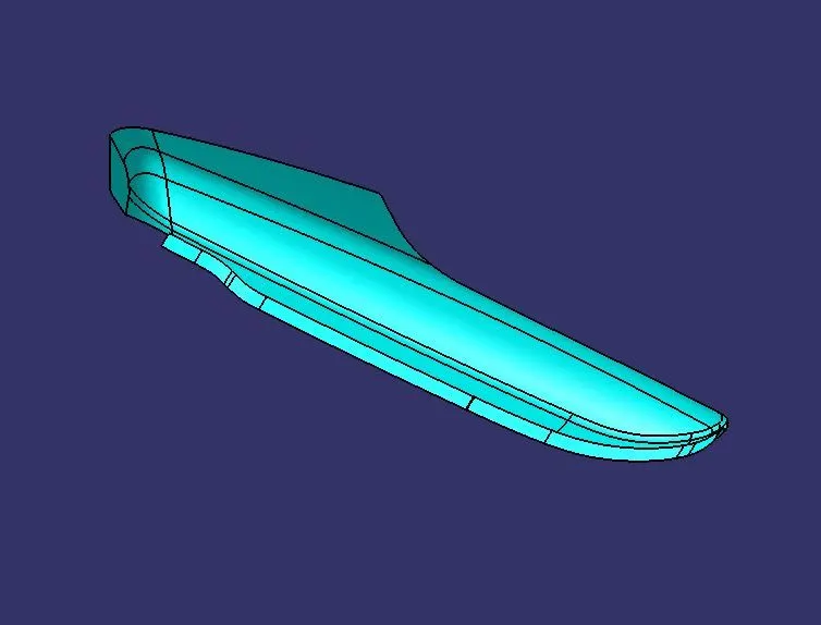
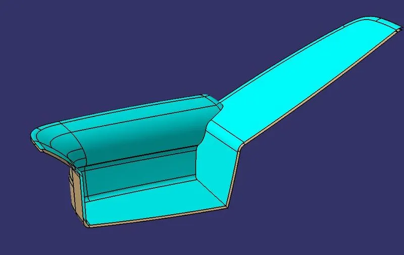
Lower substrate Door arm rest 1 Door arm rest 2
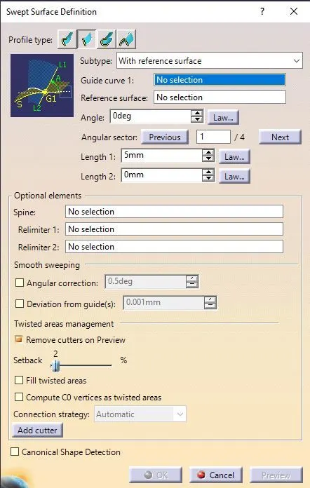
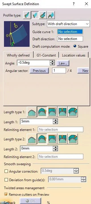
5. Class C Surfaces : Class C surafces created by using sweep tool with respect to Surface reference and tooling direction.
Sweep Tool : It is a tool where surafces can be created with respect to the surface reference and draft direction. For reference surface we need guide curve and a surface as a reference ,For draft direction sweep we need a guide curve and a drafting direction along the guide curve.
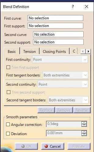
Blended Surfaces : The Blend tool is used in crating the c surfaces , These are used to fill between two small gaps ,For this we require two guide curves and the direction for blending is given along the irection to blend.
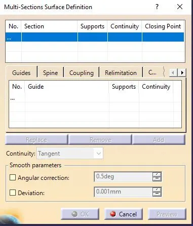
Multisection Solid : Multisection Sloid tool is used to fill the gaps between two surafces belogining to the same part. This is similar as blend but to create this we require 4 guide curves with 2 different directions.
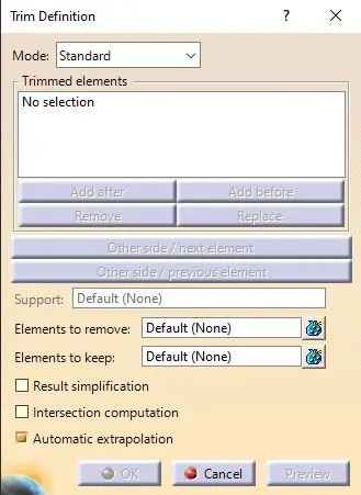
6.FINAL TRIMMING : Trimming the class A with Class C and A+C with Class B by using the trimming tool.
The trim tool is one which allows you to trim the surfaces and curves with respect to each other. When you invoke this tool trim definition dialog box displayeed,First we need to select the 1st element and selectthe second element to trim ,one side side of the trim appers as transperenr and other side to trim ,if we click on the other side the other will go transparent and trim happens.
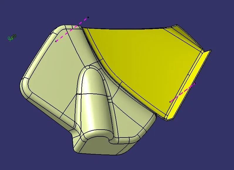
Coming to our project the final trimmed parts are given below
MAP POCKET 1 AND MAP POCKET 2 :
LOWER SUBSTRATE:
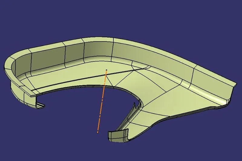
DOOR ARM REST 1 AND 2:
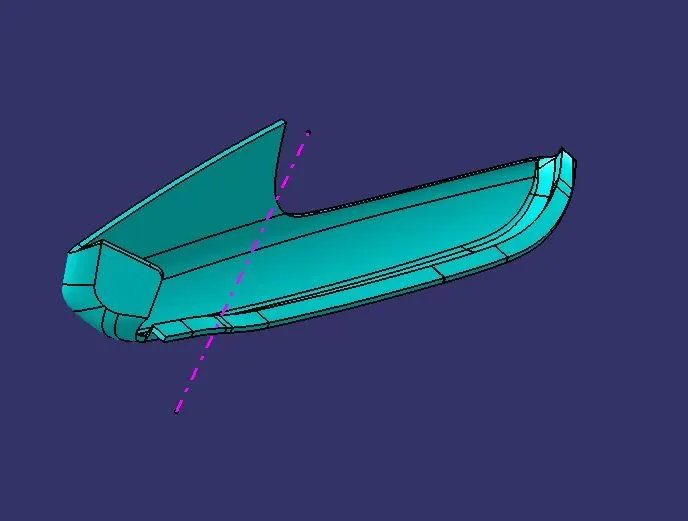
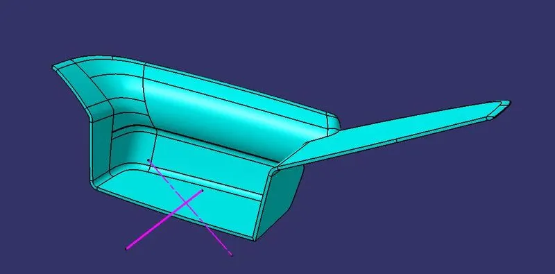
7. CLOSED SURFACE DEFINITION : Convert All the trimmed parts into closed surfaces .For this we use close surface definition tool for closing the parts.
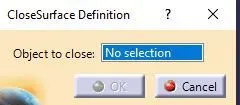
The closed surfaces of lower substrate , map pocketand door arm rest is given below
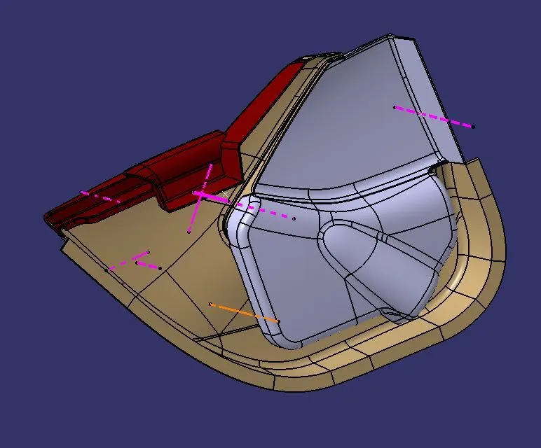
HEAT STAKES : Heat stakes are created on the closed part of the lower substrate fo attachment between the Map pocket and the Door arm rest. The ribs are given to the heat stakes for supporting them . some of the heat stakes are not given ribs because they are less than 12mm heaight and 1.6 dia.
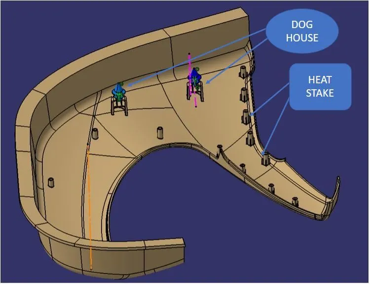
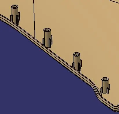
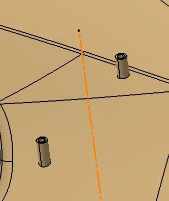
LOWER SUBSTRATE WITH THE HEAT STAKES HEAT STAKES WITH AND WITHOUT RIBS
HOLES : Holes are made on the other parts i.e. Arm rest and Map pocket
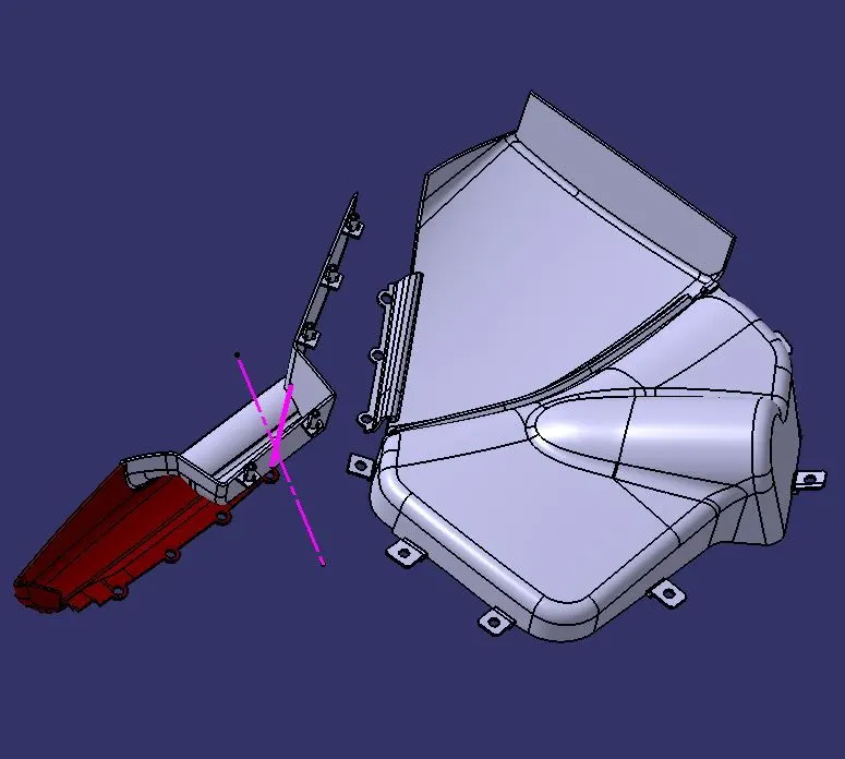
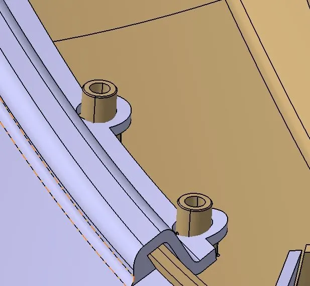
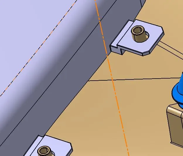
Parts with holes Heat stakes with Holes
DOG HOUSE : Dog house is created on the lower substrate for attachimg with BIW.
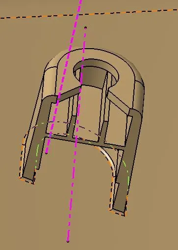
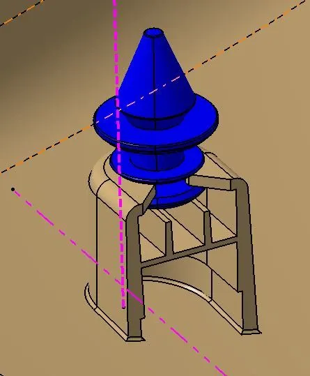
DOG HOUSE WITH PUSH PIN
DRAFT ANALYSIS & TOOLING ANALYSIS : When developing parts for plastic injection molding, applying draft (or a taper) to the faces of the part is critical to improving the moldability of your part. Without it, parts run the risk of poor cosmetic finishes, and may bend, break, or warp due to molding stresses caused by the plastic cooling. The draft analysis button within CATIA V5 will helps you quickly gather the draft angle on multiple surfaces without the need for tedious manual measurements. Therefore a minimum of 3 degrees draft anglemhas been given to the parts to be moulded.
A.MAP POCKET :
1.MAP POCKET 1
- The minimum draft angle given is 3 degrees .
- The map pocket 1 satisfies the tooling direction without any fail.
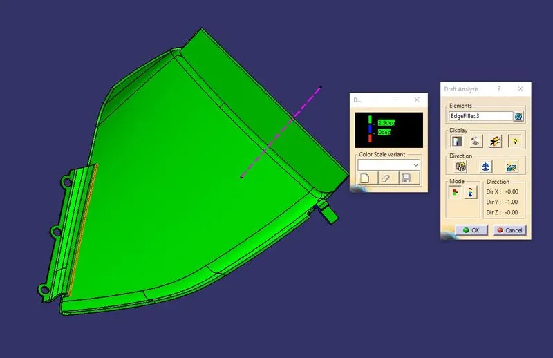
MAP POCKET 1 WITH DRAFT ANALYSIS
2.MAP POCKET 2
- The minimum draft agnle given is 3 degrees .
- The tooling axis taken is normal to the global y axis.
- Some of the places are not satisfies draft angle due to tha straight class A surface and the tooling angle is 0 degrees in that area.
- So wee need the class A designers to modify the class A.
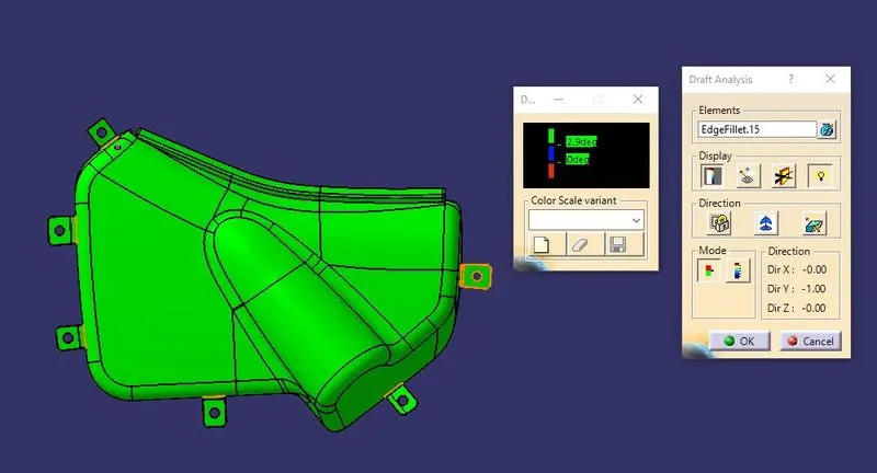
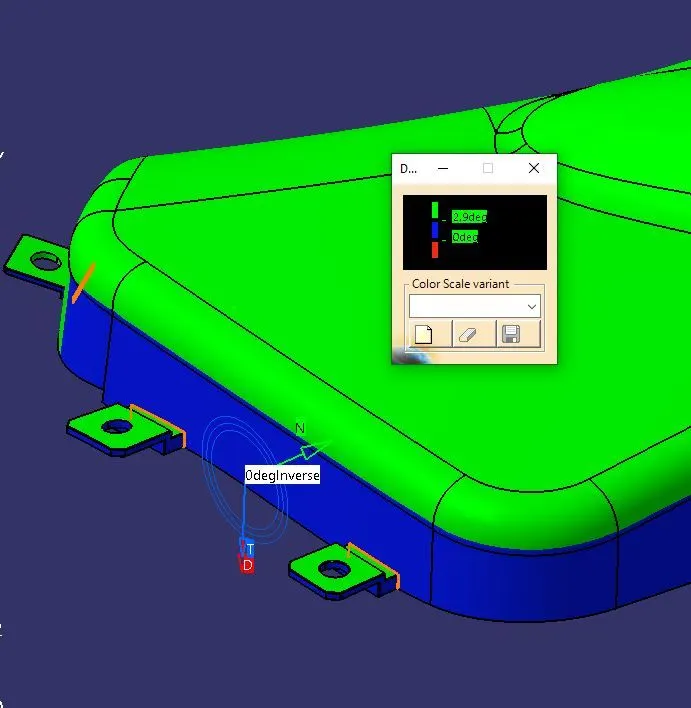
WITH MAIN TOOLING AXIS
B.LOWER SUBSTRATE :
- The min drfat angle given to the part is 3 degrees and for heat stakes the min drfat angle 0.5 degrees
- Except the small straight area the draft analysis is satisfied .
- Dog house has been satisfied the draft analysis
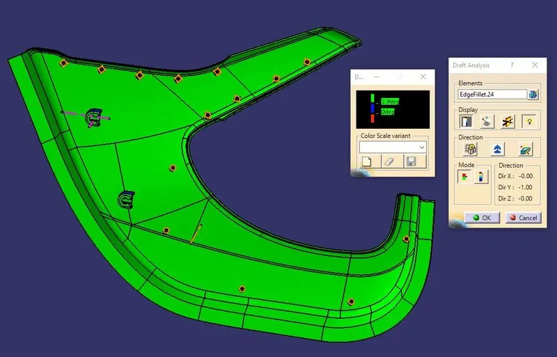
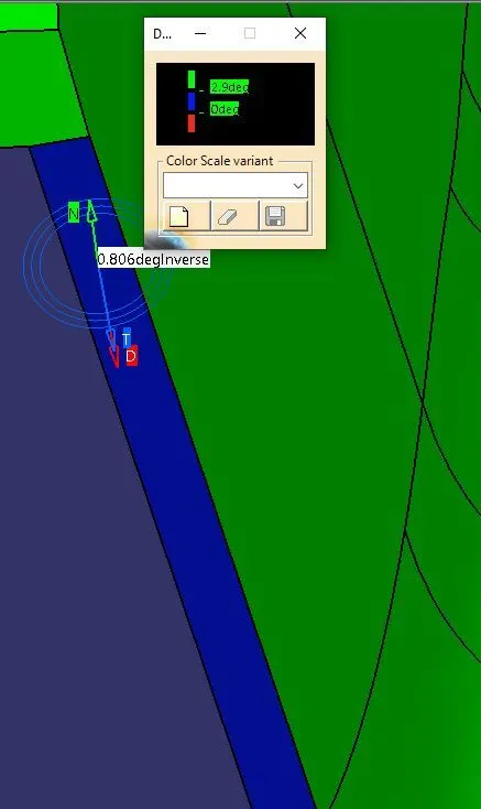
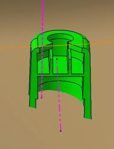
draft analysis not satisfied portion Dog house with drfat analysis
C. DOOR ARM REST:
1.DOOR ARM REST 1
- The minimum draft angle given here is 3 degrees .
- The door arm rest 1 satified the tooling direction.
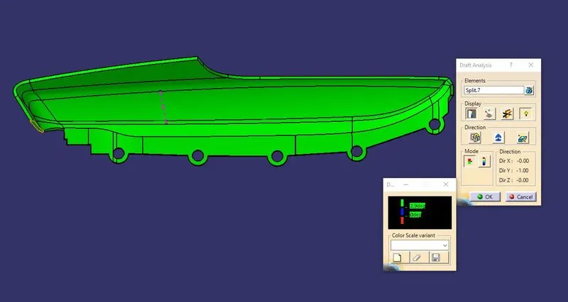
DOOR ARM REST 1 WITH DRAFT ANALASIS
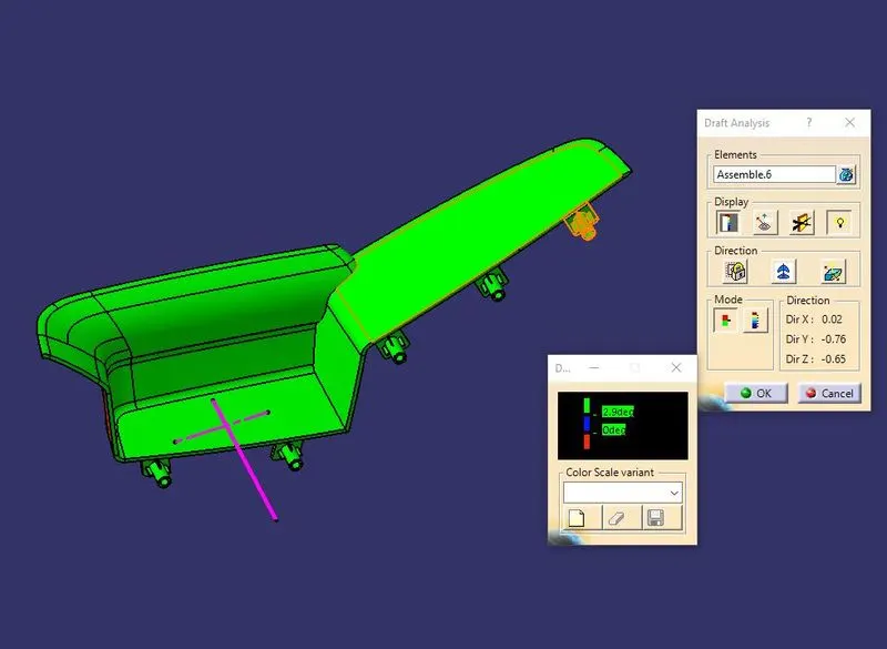
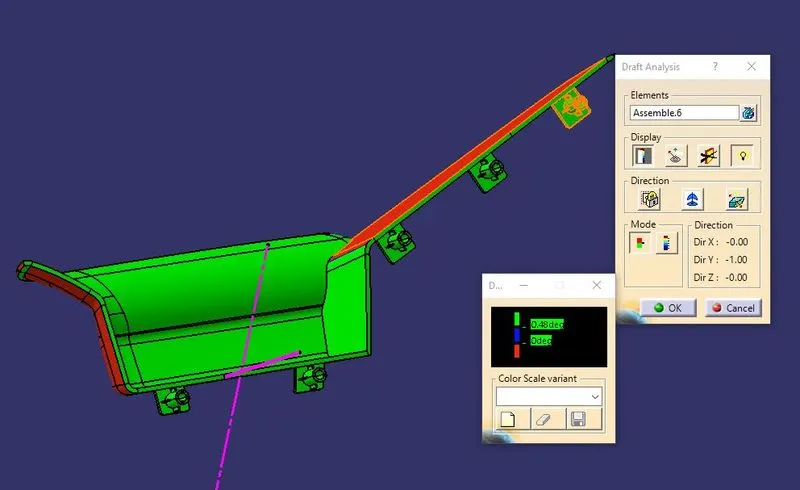
2.DOOR ARM REST 2
- The minimum draft angle given is 3 degrees
- Here there are 2 tooling axis one is main tooling axis for the part and another one side core tooling axis for the attachment features.
- Both the tooling axis satisfies the tooling directions.
Main tooling axis Side core tooling axis
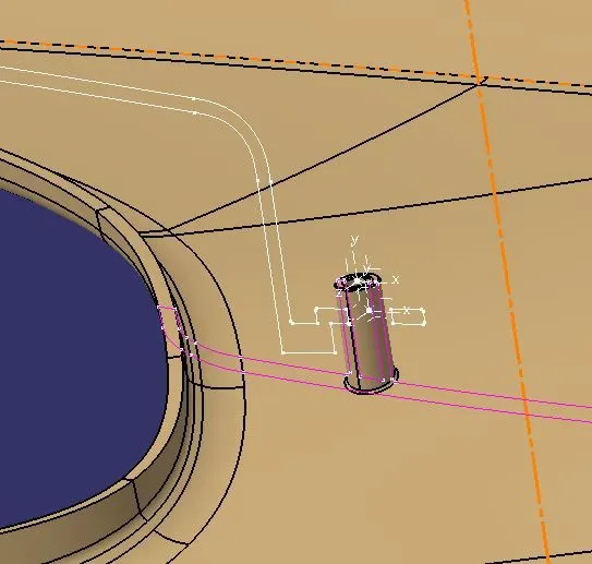
- Because some othe master sections are not given we have assumed and created ,those are given below
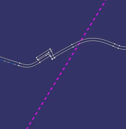
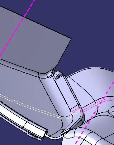
Between map pocket
Between map pocket and lower substrate
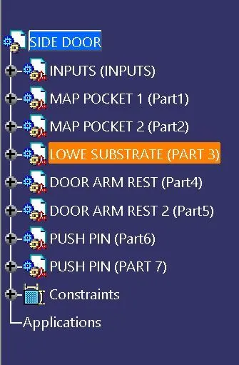
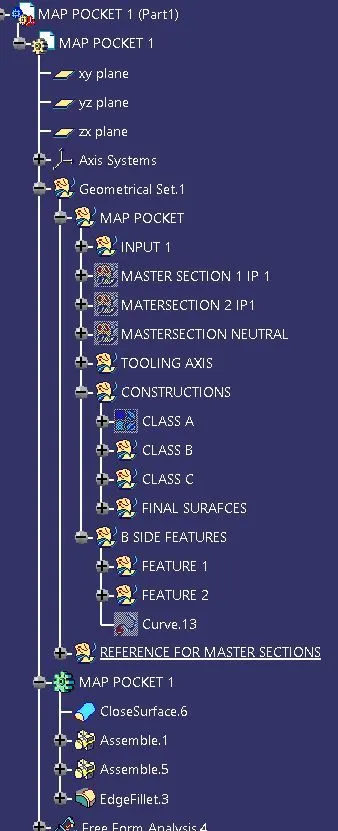
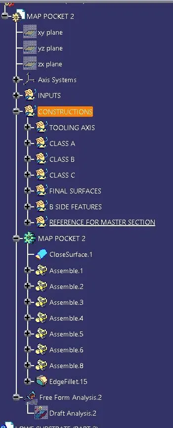
TREE STRUCTURE :
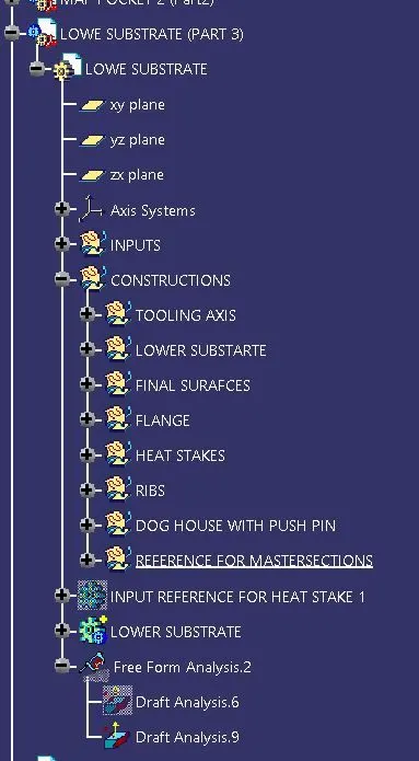
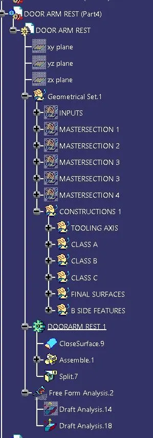
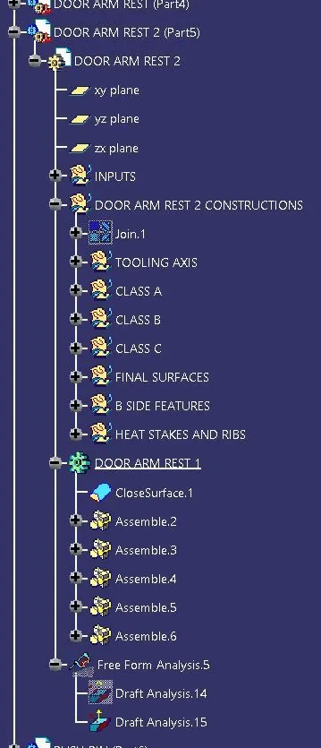
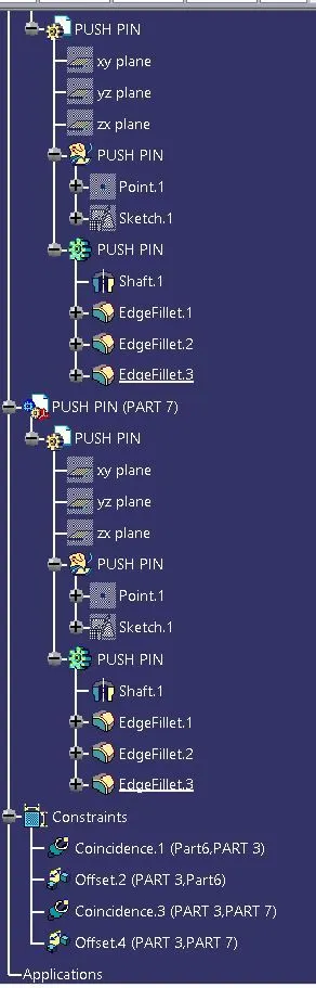
FINAL PART