Roof challenge
ROOF DESIGN AND ANALYSIS USING CATIA V5 :
Objective :
Design a roof using the provided skin data and also position bow roof rails in accordance with heat distortion and snow weight formula also find section modulus of the roof and roof rails and check the draft of the designed parts.
Software :
CATIA V5
Given Data :
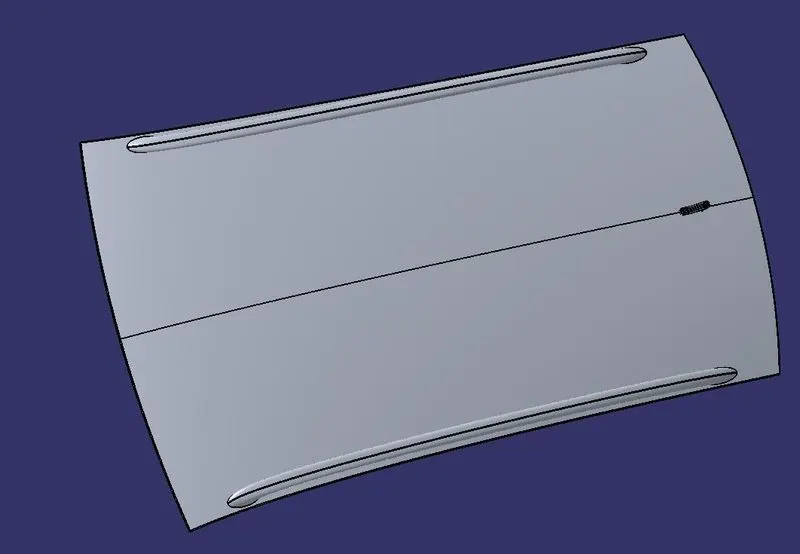
Introduction :
Roof :
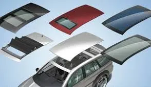
An Automobile roof is the portion of the automobile that sits above the passenger compartment and protects the occupants from sun, wind, rain and other external elements. While designing a car roof forces due to impact, falling objects, vehicle rollover, temperature, roof loading, aesthetics etc. must also be taken into account. There are different types of roofs, the most prominent are as follows
- Hardtops
- Soft tops
- Targa tops
- Glass roofs
- T-tops
Some roofs have a window on them and are called sunroofs, while convertibles have special mechanisms that allow the roof to be retracted and be stowed away through a wide array of methods depending on the design.
The roof of the car is made up of multiple parts that provide support and strength to the roof component. The actual roof sheet and the roof rails which support the roof sheet. There are 3 primary roof rails in a car the front, the centre and the rear, while additional roof rails are called Bow roof rails. The number of bow roof rails depends on the size of the roof. Headroom, visibility criteria and target region also play a key role in roof design.
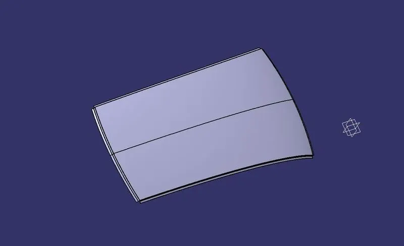
Roof Panel :
The roof is made from a sheet of at least 0.75mm. This protects the cabin from external conditions and objects. The ditch areas are spot welded to the pillars of the car and certain areas of the roof rails, welding on the upper surface is avoided in order to maintain a good aesthetic.
Front Roof Rail :
The front roof rail is made from a sheet of at least 1.25mm thickness. This part acts as a support for the roof sheet on the front it also provides a mounting area for the windshield. It is designed with support requirements, visibility criteria and headroom space in mind. The roof is fixed to the roof rails with the use of mastics while the ends are spot welded.
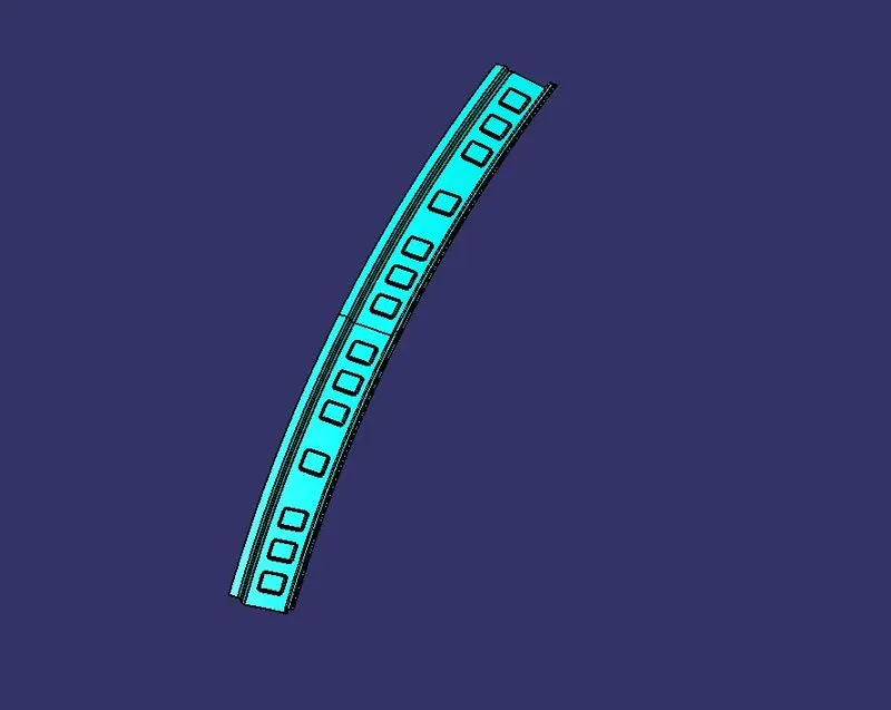
Fig. FRR
Rear Roof Rail :
The rear roof rail is made of a sheet of at least 1.25mm thickness. The rear roof rail acts as a support for the rear end of the roof and also supports the rear window in some cases also supports the rear door. It's designed in accordance with the support requirements of roof, window and rear door, and also rear visibility and headroom criteria. The roof is fixed to the roof rails with the use of mastics while the ends are spot welded.
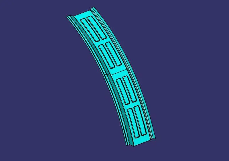
Fig. Rear Roof Rail.
Centre Roof Rail :
This is the roof rail that runs between the B pillar of the car and provides support to the centre of the roof sheet they are usually 1-2mm thick and also provide a support area for the centre cabin light mount. The roof is fixed to the roof rails with the use of mastics while the ends are spot welded.
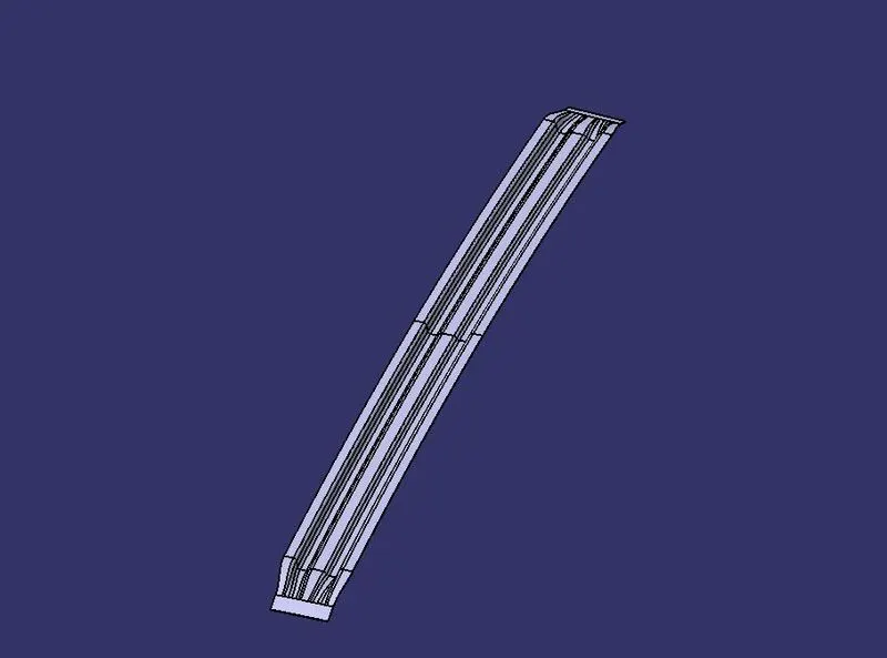
Fig Centre Roof Rail .
Bow Roofs Rails :
The bow roof rails provide additional support to the roof and are at least 1mm thick, they are positioned in such a way that they provide maximum support to the roof, Care must be taken so that they do not intrude into the headroom requirements of the car. Bow roof rails are an optional feature provided as required by the design. Small cars may have none while large ones may have 3 or more, they may also be integrated into the centre roof rail in some cases. The roof is fixed to the roof rails with the use of mastics while the ends are spot welded.
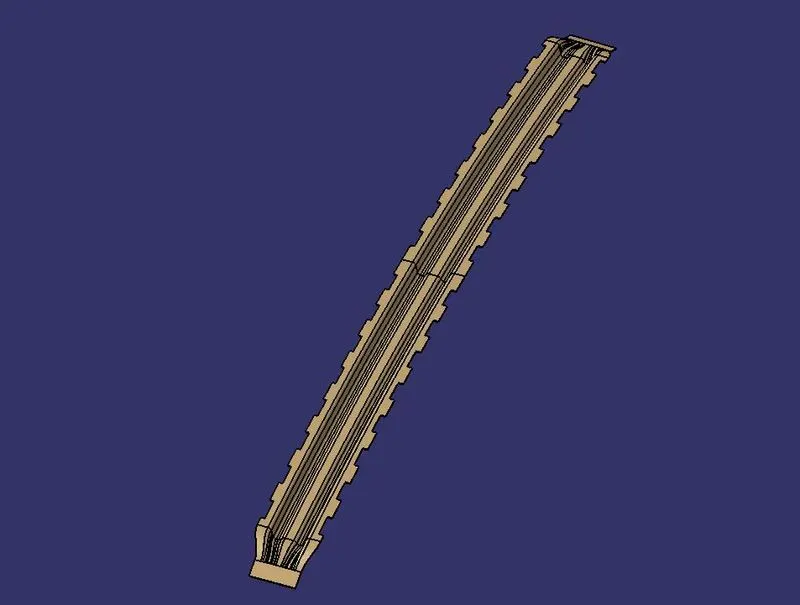
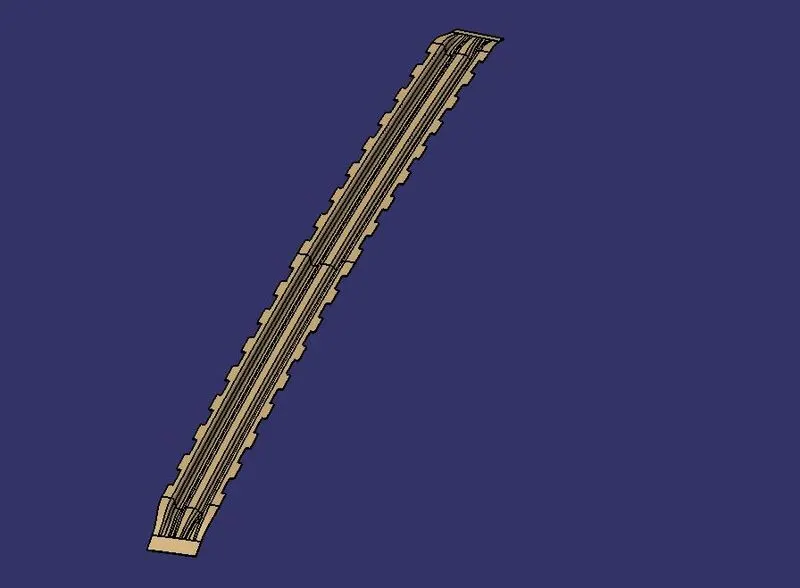
Fig. Bow roof 1 Fig. Bow roof 2
ROOF ASSEMBLIES :
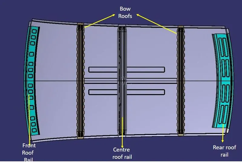
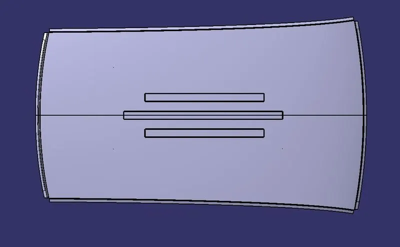
Assemble view
Roof Rail Position Analysis :
The roof rail positions are confirmed and necessary modifications are made in accordance with the snow load and heat distortion criteria.
Heat Distortion Criteria :
The roof of the vehicle is the most exposed to changes in temperature, these changes cause deformation in the roof. In order to prevent failure of the roof due to excessive thermal stress, the roof rails must be placed in the correct locations. Improper designing of the roof may cause warping, cracking and failure of mounts.
This calculation is done to find if the roof under thermal stress deforms within set limits.
It is calculated using the formula
Here we use the analyse the spans between the roof rails.
| SPAN 1 (F)(FB) | SPAN 2 (FB)(C) | SPAN 3 (C)(RB) | SPAN 4 (RB)(R) | |
| L (mm) | 2081.411 | 2081.411 | 2081.411 | 2081.411 |
| Rx (mm) | 5738.62 | 4993.423 | 4025.98 | 3252.543 |
| Ry (mm) | 2550.82 | 6112.632 | 10335.95 | 14772.017 |
| t (mm) | 0.75 | 0.75 | 0.75 | 0.75 |
| R (mm) | 3531.77 | 5496.633 | 5794.81 | 5331.24 |
| R^2/t (mm) | 17265108.36 | 41435162.26 | 43363772.41 | 36518444.19 |
| l (mm4) | 411.93 | 341.593 | 318.98 | 318.97 |
| W (mm) | 1.68 | 2.04 | 2.10 | 1.27 |
From the values of "W", we can see that All values are within distortion limits, therefore, the roof design is cleared fo the next stage.
Snow Load Condition :
The roof of a vehicle is normally not designed to hold up weight but for regions with snowfall, it must be properly reinforced to hold up the weight of accumulated snow on the roof, if done improperly it may cause the roof to bend and intrude into the passenger compartment which is dangerous. This calculation is done in order to check if the location and strength of the roof rails are enough to avoid plastic deformation of the roof.
The formula for the snow load analysis is as follows
| BOW 1(F) | BOW 2(C) | BOW 3(R) | |
| Iy (mm4) | 5.19*10^8 | 6.04*10^8 | 5.16*10^8 |
| t (mm) | 1.25 | 1.25 | 1.25 |
| Y (mm) | 505.365 | 411.177 | 581.33 |
| Ly (mm) | 2030.97 | 2030.97 | 2030.97 |
| My (mm2) | 770987.37 | 666384.12 | 842719.22 |
| LX (mm) | 1137.51 | 1087.656 | 1059.44 |
| α (mm4) | 0.997 | 0.788 | 0.945 |
| L1 (mm) | 505.365 | 411.477 | 581.33 |
| L2 (mm) | 411.477 | 581.33 | 440.435 |
| S (mm) | 457.421 | 496.40 | 510.89 |
| Rx (mm) | 4526.556 | 3761.206 | 4252.165 |
| Ry (mm) | 2606.475 | 6018.784 | 10781.245 |
| R (mm) | 4747.8313 | 6513.34845 | 5298.38975 |
| Qr | 3.377 | 2.4 | 7.21 |
From the value of "Qr", we are able to see that all values are above 3.1 except bow roof 2.
Draft Analysis :
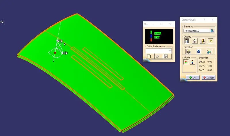
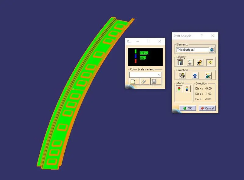
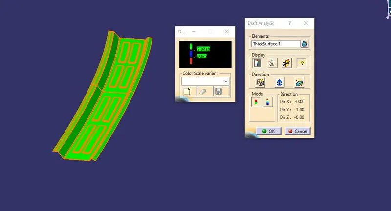
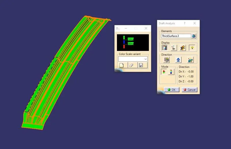
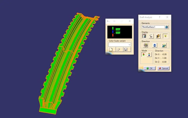
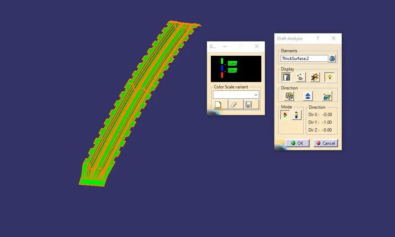
The draft of the part is the amount of taper of the edges to the striking mould of the part. The draft allows for easy removal of the part from the striker while an improper draft or negative draft causes the part to deform or get stuck on the mould.
Here using software we check if all the parts have a proper draft and are formable, green denotes positive draft and red denotes a negative draft.
Roof Panel :
Front Roof Rail :
Rear Roof Rail :
Centre Roof Rail :
Bow Roofs :
Section Moment of Inertia Ana;ysis Values:
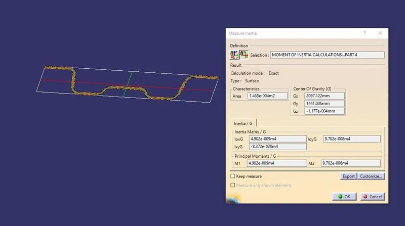
Section moment of inertia is used to predict the amount of deformation and deflection of a part. A higher moment of inertia is preferable as it reduces the amount of deflection for a given force. The thickness of the part and addition of flanges and embosses increase the section inertia of the part. Here the master sections of the roof and roof rails and their section analysis are given.
Centre Roof Rail :
Bow Roofs :
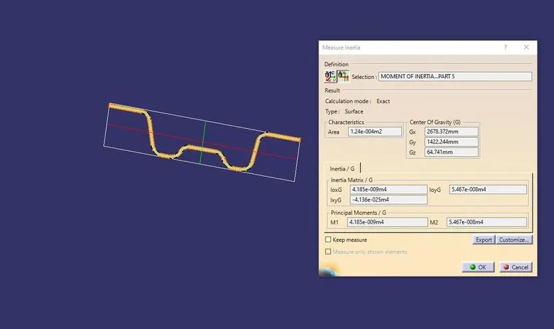
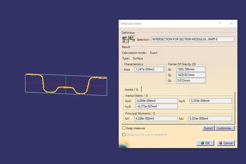
Bow roof 1 Bow roof 2
Conclusion :
Thus the roof of the car is designed as per the given skin data and necessary reinforcements are given. The roof is also analysed as per the heat distortion and snow load conditions and is found that the snow load condition of centre roof and bow roof is not within limits, So we added embossings to the roof panel for more strength. Draft analysis is also carried on all the components and there are no issues in this regard. Therefore the roof design may be sent to the next step of the design process.