Week 11 - Final project
AIM - Creation of Solid Door Trim Panel from a given Class A Surface of Door Panel.
INTRODUCTION - The door panel of a car matches rest of the interior of car door. It houses the necessary functional attachments required for better accessibility in a vehicle. These door panels are made up of plastic components and are forme from Injection Molding.
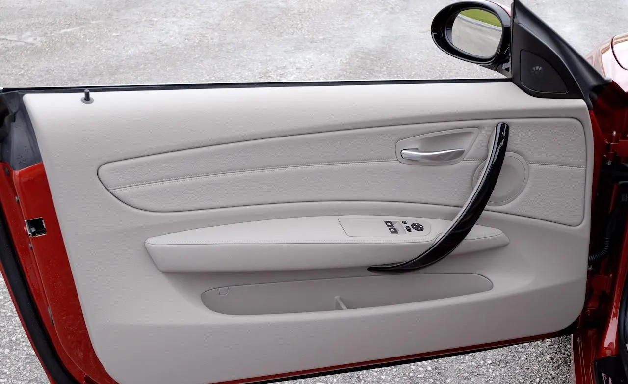
INPUT :
- Class A Surface by the standards of OEM.
REQUIRED OUTPUT :
- LOWER SUBSTRATE
- INNER MAP POCKET
- OUTER MAP POCKET
- DOOR ARM REST 1
- DOOR ARM REST 2
PROCEDURE FOLLOWED :
- Extraction of Class A Surface from input
- Creation of Tooling Axis by understanding the Tool Positions
- Draft Analysis of Class A Surface Along Tooling Axis.
- Creation of Class B
- Closing Class A and Class B surface to form Class C Surface
- Forming Solid Body from Closed Class C Surface
- Performing Draft Analysis of Solid Body
- Creating Engineering Attachment features for the final component by 3-2-1 Principle
VALUES TAKEN :
The Values thaken are constant throughout and for all the parts
- Draft : 0.5 to 3 degrees
- Fillet : 1mm to 3 mm
- Offset of Class B Surface : 2.5 mm
- Thickness of Heat Stakes : 2 mm
- Distance between Heat Stake Hole and Heat Stakes : 0.5 mm
- Thickness of Attachment Flanges : 2.5 mm
LOWER SUBSTRATE :
Extracted the Lower Substrate from the given Master Section.
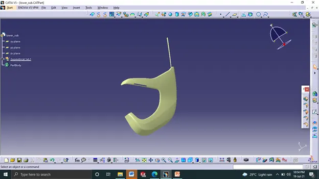
Filled the gaps and performed trims on the extracted surface to form a proper Class A Surface of Lower Substrate
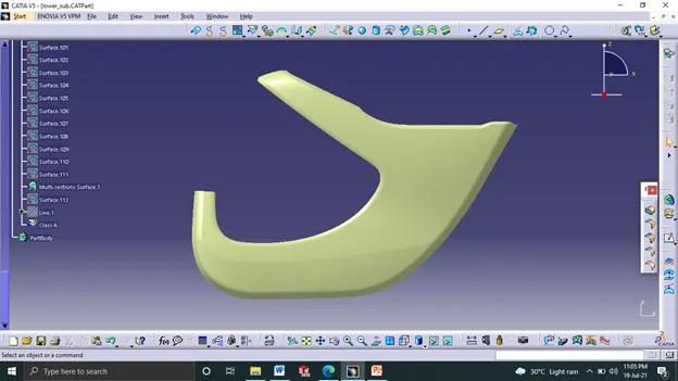
Took a point on the surface and Created the Tooling Axis along the direction in mold dies can perfom molding.
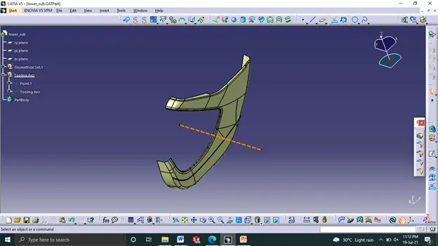
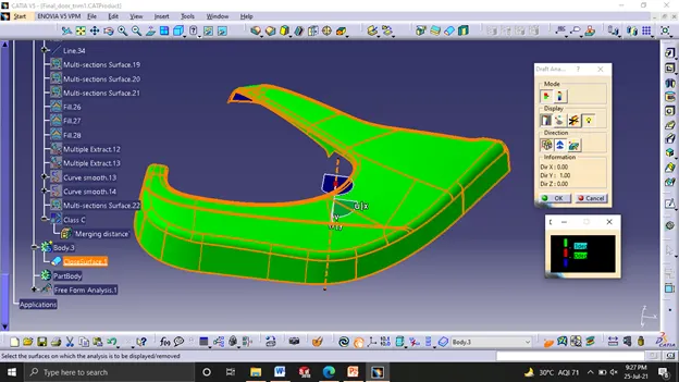
Perfoming Draft Analysis of Class A Surface
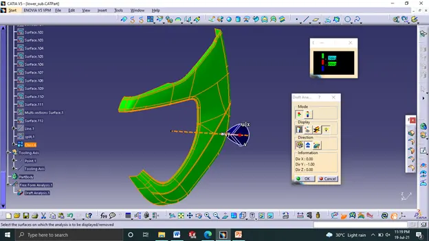
After Offsetting the Class A Surface by 2.5 mm, Class B surface is formed. Now the Class A and B Surfaces are joined to make Class C Surface.
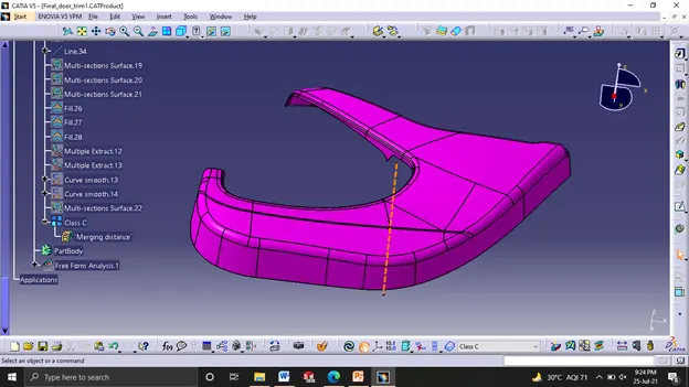
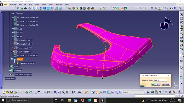
Close Surface Command is being applied to the Class C Surface
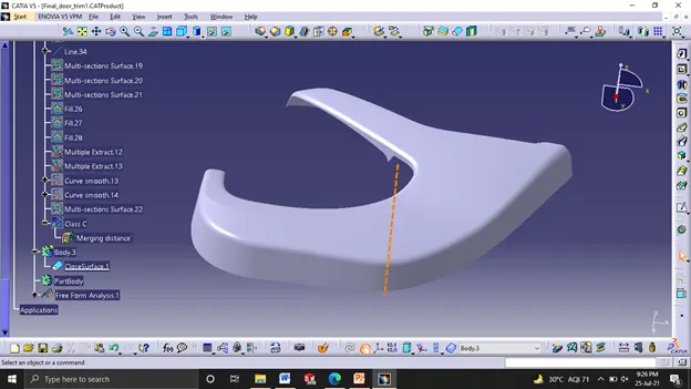
Solid Part of Lower Substrate is created
Draft Analysis of Lower Substrate Solid Part
OUTER MAP POCKET
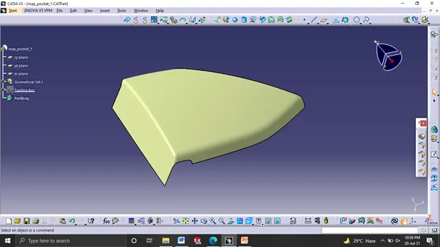
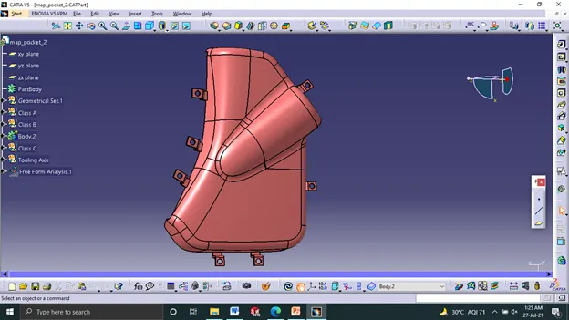
Extracted and Complete Class A from the Master Section
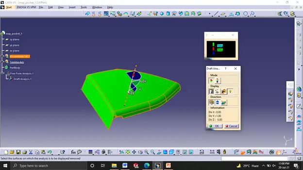
Draft Analysis of Class A after the Tooling Axis is created on the surface by taking a point and the direction of movement of the tool.
After Offsetting the Class A surface by 2.5 mm we get the class B surface. Now, the surfaces are joined and closed to get the class C surface
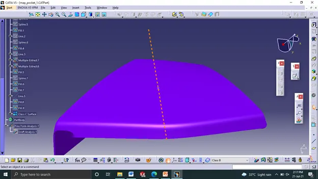
Close Surface command is applied to class C
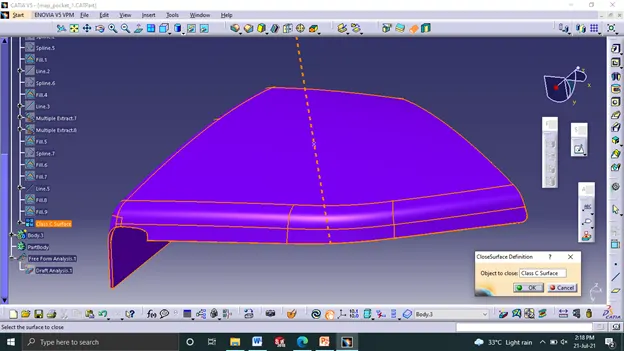
Solid Part of Outer Map pocket is obtained from the Closed Class C Surface.
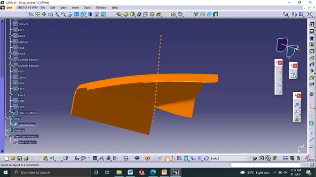
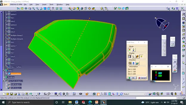
Draft analysis of the solid body along the tooling axis
INNER MAP POCKET
Extracted and complete Class A surface of Inner Map Pocket from the Master Section
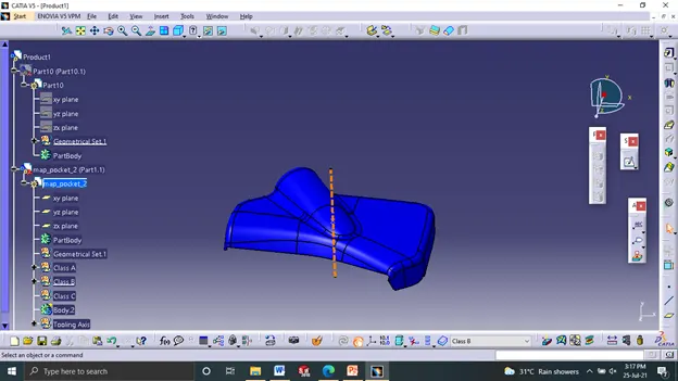
Created Tooling Axis on the surface and perfomed draft analysis along the tooling axis
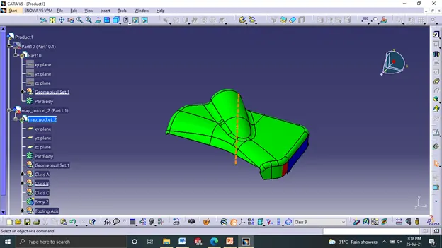
Then after the draft analysis was performed, the Class A surface was offsetted by 2.5 mm to get the class B Surface and both are joined and closed to get the Class C Surface.
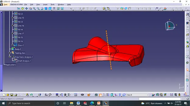
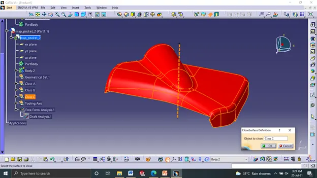
Close Surface Command is Applied to Class C
Solid Body of Inner Map Pocket Obtained from Close Surface
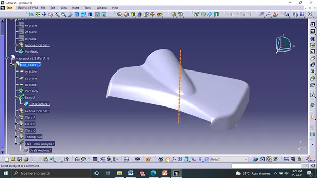
Draft Analysis of Solid Inner Map Pocket Solid Body
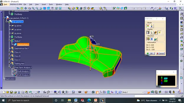
DOOR ARM REST 1
Extracted and Repaired the Class A surface of the Door Arm Rest from Master Section.
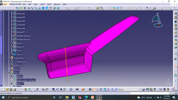
The Tooling Axis is Created on the Surface and Draft analysis is performed on Class A
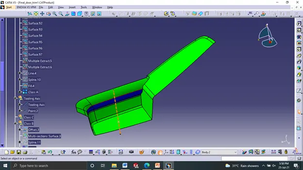
The Class A is offsetted to form the Class B Surface and when both are closed and joined, Class C is formed
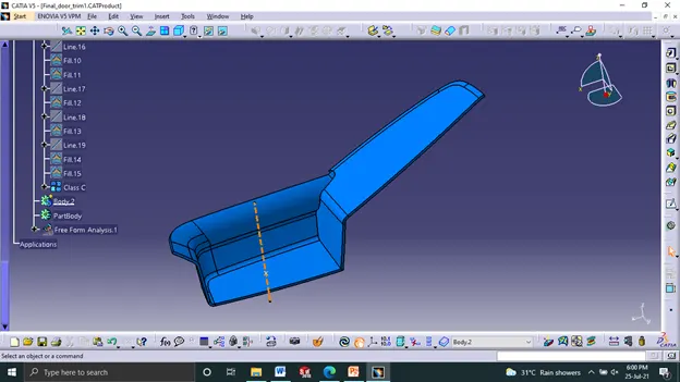
Applying Close Surface Command to Class C
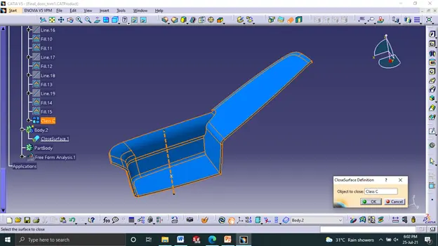
Solid Body of Door Arm Rest 1, formed from close surface
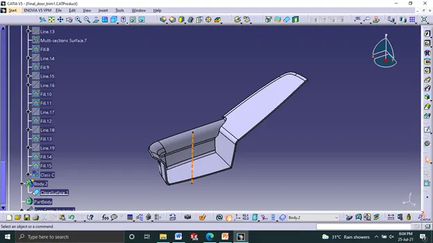
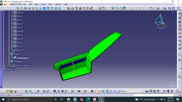
Draft Analysis of Solid Door Arm rest 1
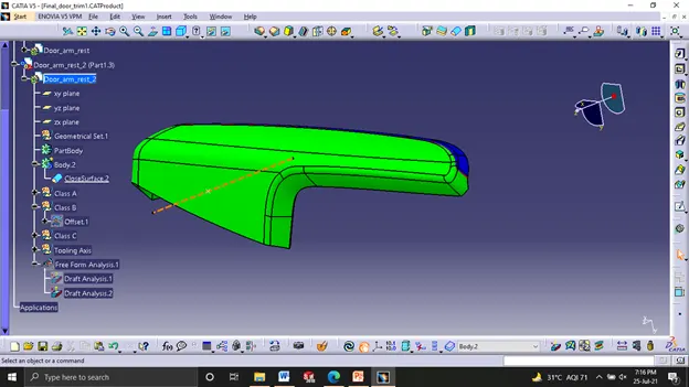
DOOR ARM REST 2
Extracted Class A of Door Arm Rest 2
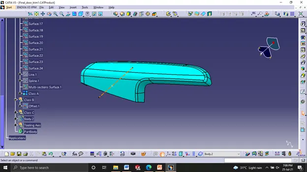
Draft Analysis of Class A after the Tooling Axis is Formed along the direction of the die movement and on the surface
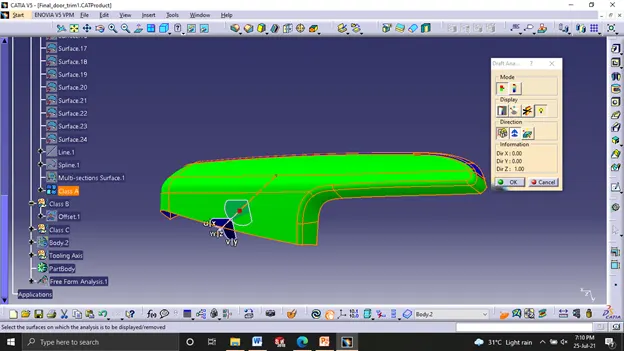
The Class A is offseted to form Class B and the both are joined to form Class C
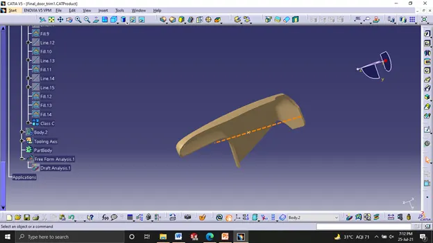
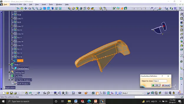
Close Surface is Applied to Class C
Solid Body of Door Arm Rest 2
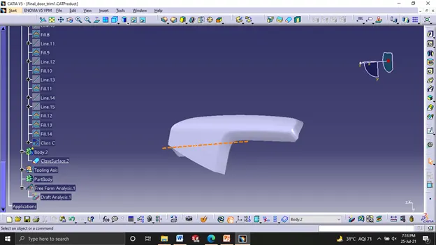
Draft analysis of Door Arm Rest 2 along the Tooling Axis
ENGINEERING ATTACHMENT FEATURES
- FLANGE
The is created on All the parts except lower substrate. Holes are made on the flange for the Heat Stake Attachments to go through and Fix the part
Iso-Constrained Sketch of Flange
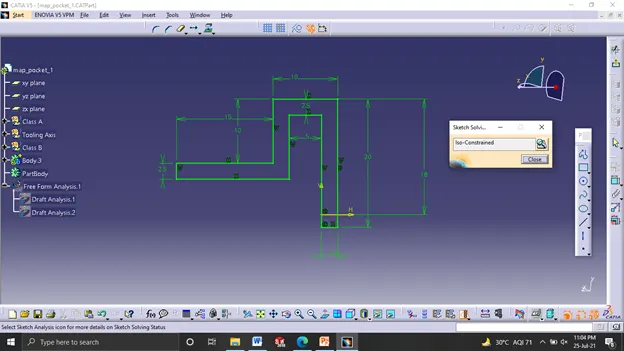
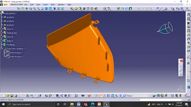
Flanges created on the Outer Map Pocket by 3-2-1 Principle
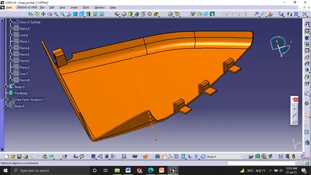
A diameter 9 mm part is created and Boolean Remove Operation is followed ot create the holes on all the flanges.
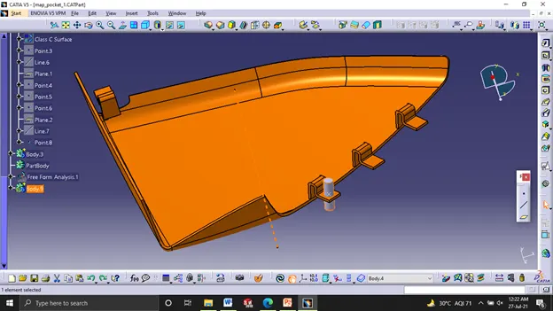
Heat Stakes -
The Heat Stakes are created on the mating part by taking a 8 mm diameter circle and then Adding it to the Lower Substrate(mainly). It is further Offsetted by 2 mm inside for the required thickness. The distance of Heat Stake from the flange face has to be kept within 7mm
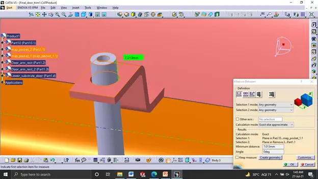
Finished Outer Map Pocket with Flange Hole and Heat Stakes.
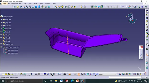
Finished Door Arm Rest 1 with 1 Flange hole
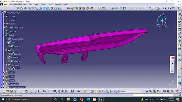
Finished Door Arm Rest 2 with flange and holes
Finished Inner Map Pocket with flanges and holes
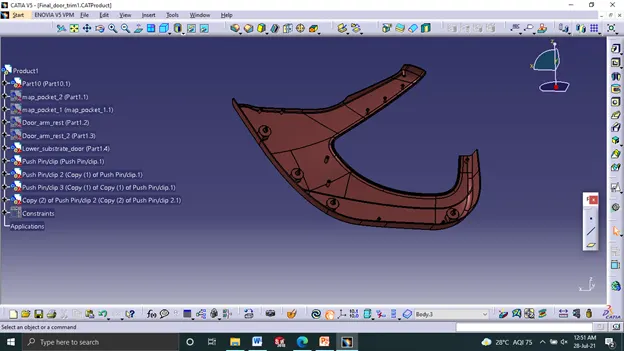
Finished Lower Substrate with Heat Stakes, Dog House and Push Pin
DOG HOUSE- It is a supporting engineering attachment feature. It avoids breakeage of components during ejection from the mold cavity. It is built on the B Surface. It hosts a number of engineering attachment features. Here it is used to house the Push Pin for the attachment of the Lower Substrate.
A draft of 1.5 degrees is given to the dog house
A lifter Axis is created in the dog House.
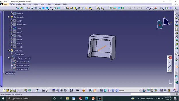
Draft Analysis of the Dog House Along the Lifter Axis
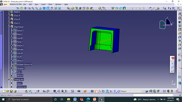
Push Pin on Dog House on the Lower Substrate
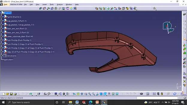
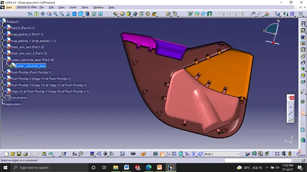
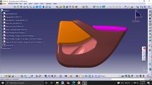
COMPLETE ASSEMBLY
The Complete Door Trim Assembly from the Inner Side
From the Outer Side
CONCLUSION
All the above functions are performed on the master section to obtain The Final Door Trim Panel along with the necessary draft analyses on the same.