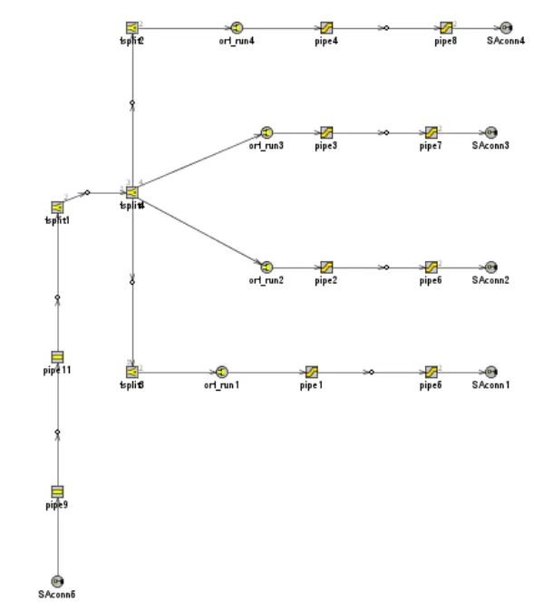
Week-11 : Discretization of 3D intake manifold using GEM-3D
AIM:
- Tutorial- single cyl DI add case 2 with discretization length 0.1 mm for intake runner and compare with default case 1
- Parameters-Torque, BSFC, max cylinder pressure
- simulation time
- Explore tutorial no 2 (GEM3D) - “Building intake manifold from STL model”
INTRODUCTION:
Discretization is the process of dividing a volume into smaller subvolumes of equal or different length. Flow parameters like pressure, temperature, density etc.. are calculated in each subvolumes.
If the explicit solver is used the time step required is directly proportional to the discretization length. Smaller the discretization length more number of subvolumes will be formed and hence takes more time to solve. The proportionality between the time step and discretization length is shown below,
`trianglet alpha (trianglex)/(c + |U|)`
Where, `triangle t`– explicit time step
`triangle x`– discretization length
C – speed of sound
U – flow velocity
GT-suite provides some recommendations on deciding discretization length. For engine simualtions, the discretization length of intake system can be set to 0.4 times the bore and for exhaust system the discretization length can be set to 0.55 times the bore. The discretization length should be decreased for acoustic simulation as well as engine performance simulation at engine speed more than 6000 rpm.
1. Tutorial- single cyl DI add case 2 with discretization length 0.1 mm for intake runner and compare with default case 1
- Parameters-Torque, BSFC, max cylinder pressure
- simulation time
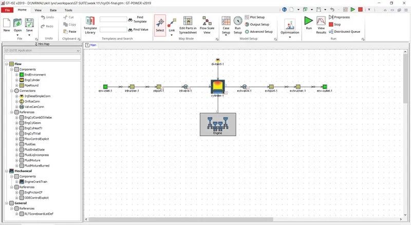
This model shows the 1CylDI engine
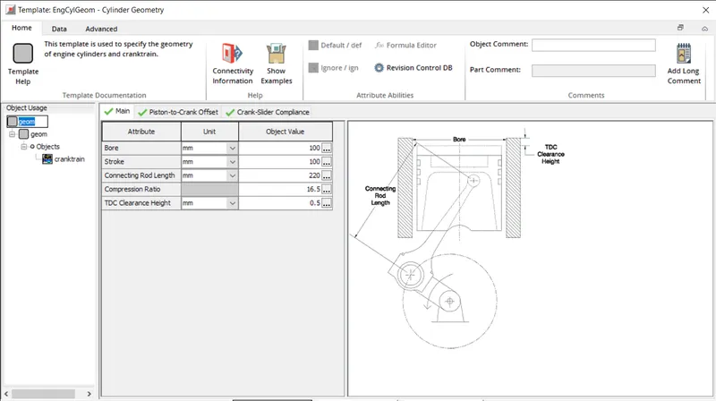
The below snip shows the cylinder geometry of the engine
The engine cylinder template shows the heat transfer and combustion object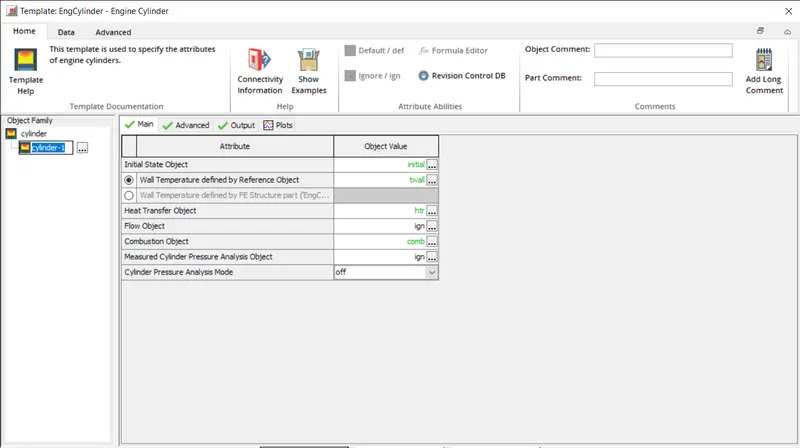
The injector template is used to define the parameters like mass of fuel injected to 80 mg. The fluid type is set to diesel-2 and the injected fluid temperature as 300k. The start of injection is set to -5 degrees of crank angle and duration of injection as 18 degree.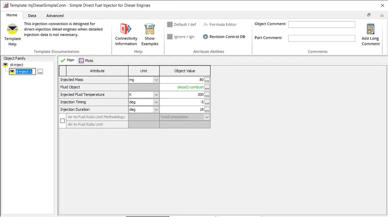
The intake port parameters are defined in the piperound template. The inlet and outlet diameter of 40 mm and the length of 80 mm and discretization length is defined as parameters.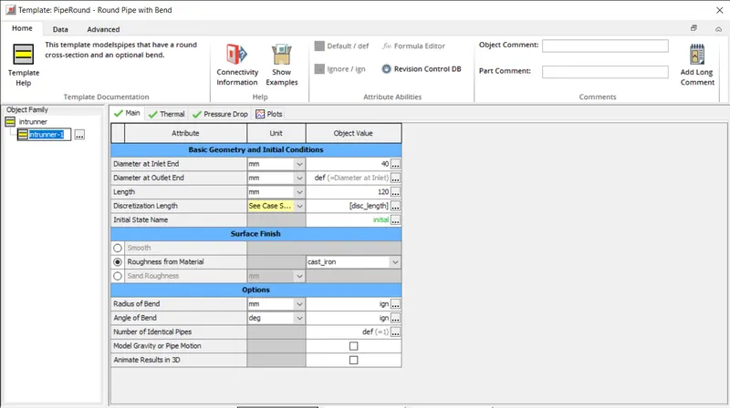
In thermal tab the imposed wall temperature is set to 450k and heat transfer corelation is set to Colburn.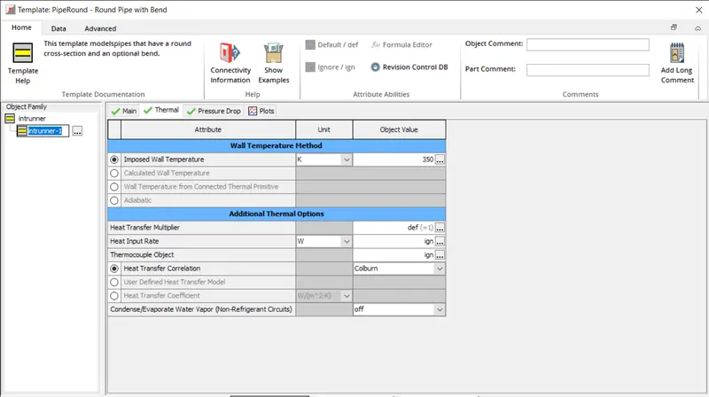
CASE SETUP:
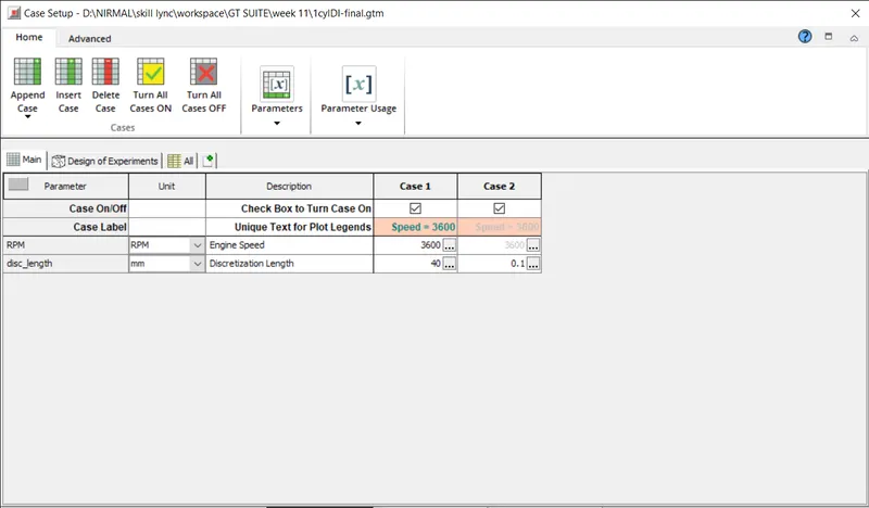
The below case is run with two case setup in which first case run with discretization length of 40 mm and second case with discretization length of 0.1 mm.
RESULTS:
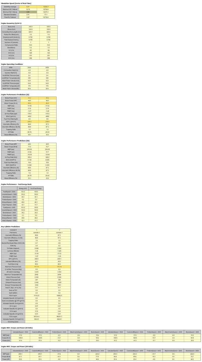
From the results we can say that on deceasing the discretization length the torque decreases, BSFC increases and maximum incylinder pressure decreases. The time taken for simulation increases.
|
DISCRETIZATION LENGTH |
40 mm |
0.1 mm |
|
SIMULATION TIME |
5.97 |
12684.1 |
|
TORQUE |
96.2 |
95.9 |
|
BSFC |
238.2 |
238.9 |
|
MAXIMUM PRESSURE |
117.11 |
115.18 |
2. Explore tutorial no 2 (GEM3D) - “Building intake manifold from STL model”
The GEM3D is launched and a new model is created by selecting new from the home tab and click on finish and making sure that the document selection on the left is set to GEM3D (.gem)
IMPORTING THE SHELL FROM AN STL FILE:
The first step is to import the intake manifold from an STL file. To import the shell, select import 3D from the home tab. Browse for the plenum.stl file located in examples > acoustics > non-linear directory.
GEM3D will create a mesh shape component from the imported shape and add it to the model.
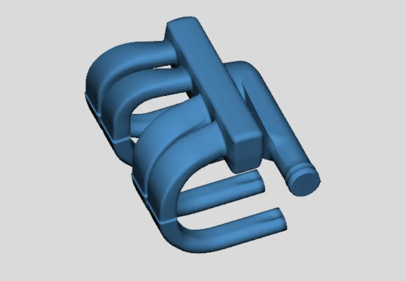
SEPARATING SECTIONS BY CURVES:
Notice that the inlet and the ends of the 4 intake runners are closed. We need to remove these caps so the ends are open and available for flow. To do this, we will use the Separate By Curves operation. This will separate the geometry into parts based on changes in the surface of the object. This process will also separate the intake runners into two different sections near the area change at the top of the runners. Ensure the part is selected and choose Separate By Curves from the Shape Operations group in the Convert tab. The tolerance controls how sensitive this operation is to changes in the surface area of the part. A Tolerance of 1.0 should be used for this operation. Click OK. You will obtain a separated intake manifold as shown in the screenshot below
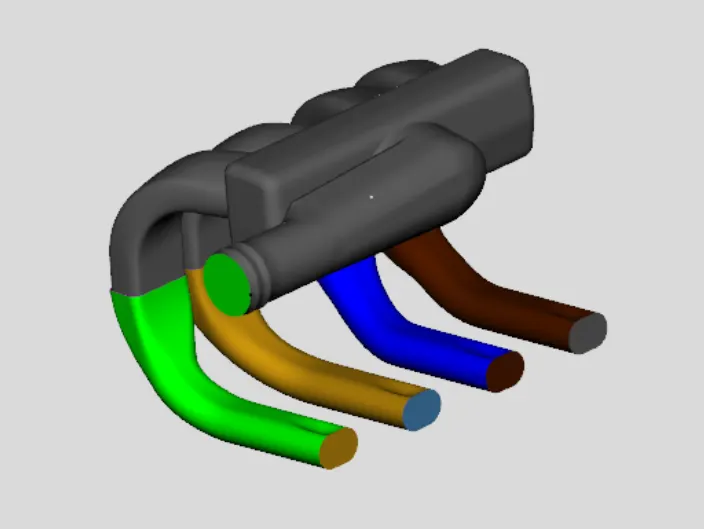
Now that the end sections of the runners and plenum are separated from the main shape, we can delete them from the model. To do this select the 5 end sections and press the delete key.
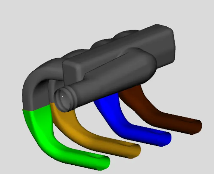
USING THE CUTTING PLANE:
Now that the end caps have been removed, we can continue separating the shape into sections that can be represented by pipes and flowsplits. We will start by separating off the 4 runners from the manifold since the runners can be represented by pipes. To do this we will make use of the cutting plane operations available in the Cutting Planes group in the Convert tab. To enable the cutting plane, select 3 Points Cutting Plane from this group. A cutting plane can then be created by clicking on 3 points on the model to define a plane. Since we want to cut off the runners, let's pick 3 points on the underside of the manifold block.
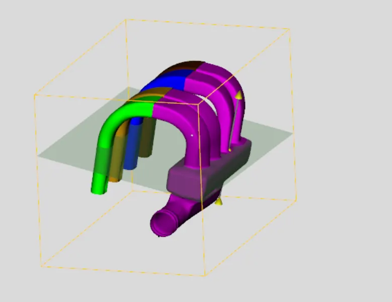
Once the cutting plane is in place, we need to select the mesh shape that we want to cut. This is done by selecting the mesh shape in the graphical window. When selected, the shape will turn magenta in color. Once the mesh shape is selected, we need to clip the runners. To do this, select Clip Shape from the Shape Operations group in the tab Convert, or select press the Clip button in the Plane Control window. GEM3D will separate the mesh shape along the cutting plane and create the new mesh shapes, as shown in the image below
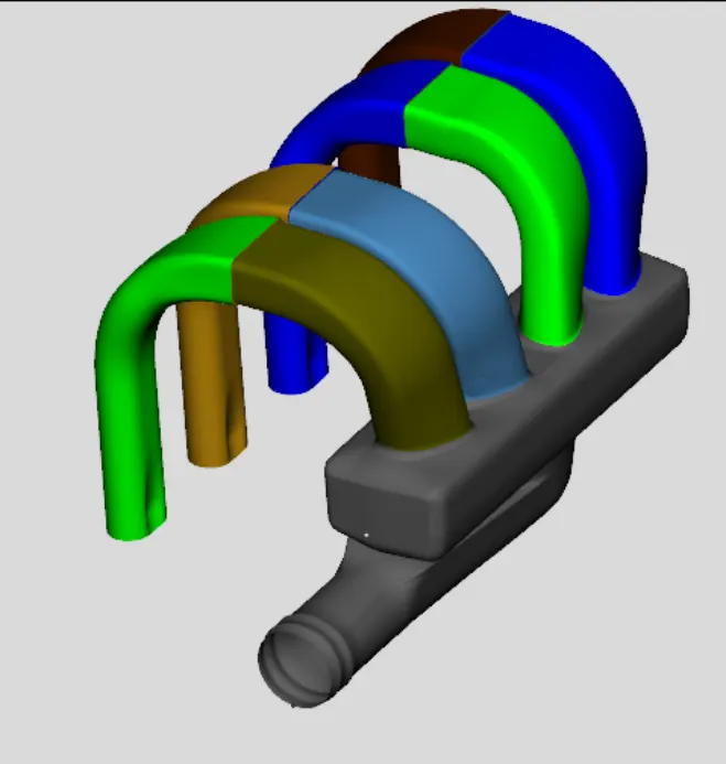
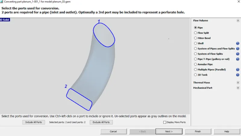
CONVERTING SECTIONS INTO FLOW COMPONENTS:
Once we have sections that can be represented by pipes or flowsplits we need to convert them into flow components. This is done with the convert mesh operation. To begin the conversion, right-click on the first section of the first runner and select Convert Shape to Component. This will open the convert mesh window, shown in the image below. The first thing we need to do in this window is select the conversion geometry type we would like to convert to. Since this particular shape is a pipe, select Pipe. Click next. Select Multiple Bends since it has more than 1 bend.
Next We need to choose which diameter to use for this cross section using the Measurement Location > Custom Plane for Port 1. This will place a small green plane on the section in the graphical window. This plane can be translated along the pipe using the mouse to select the place on the section where the diameter should be taken. We want to choose a location that is far enough away from the end where the effective diameter becomes fairly constant. Assume that the diameter stays constant throughout the pipe. Therefore select for Port 2 the check box Define from Port 1. Once in place, press Next and you will see the created component.
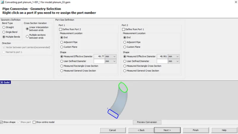
Confirm that the Wall Thickness is set to 1 mm in the Geometry tab of the Calculated Geometry window and press Next again
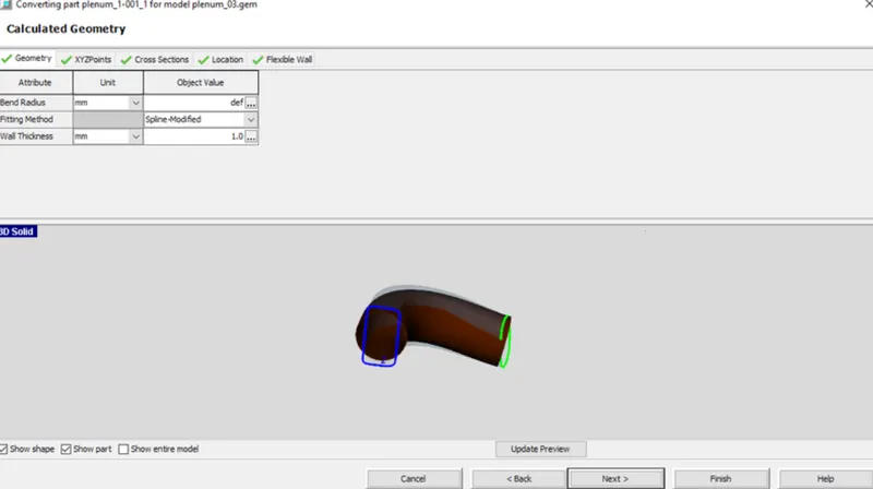
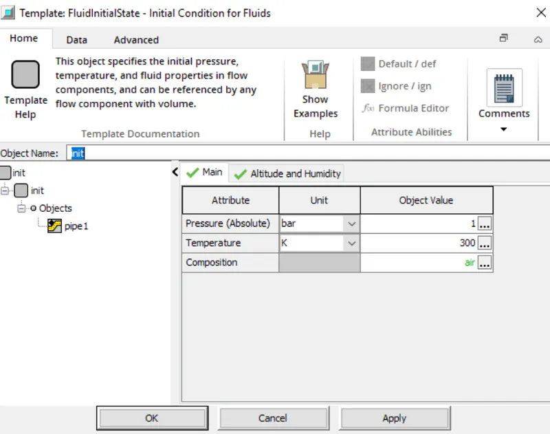
Go to the main tab and type init for the Initial State Name. We can define the initial state directly in GEM3D by double-clicking on the name "init". This will open a 'FluidInitialState' template where we can define the Pressure as 1 bar and the Temperature as 300 K. We can get the properties of air from the template library by right-clicking in the cell for Composition and choosing value selector. In the value selector scroll down and choose the "air" 'FluidMixture' object. Click OK to close the fluid and initial state objects.
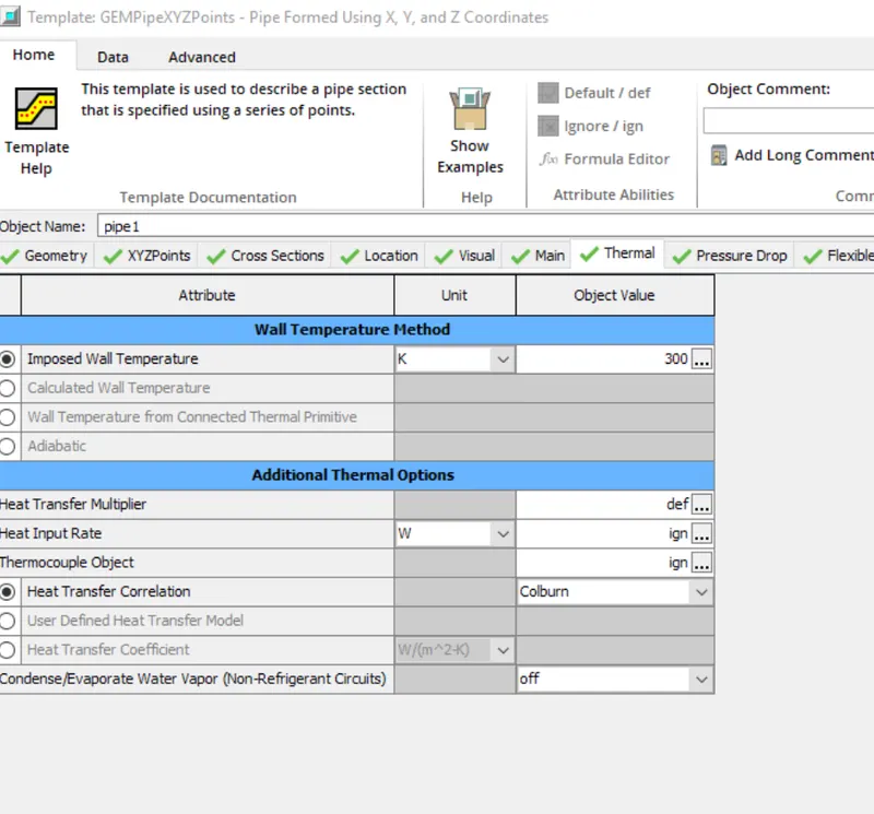
Go to the Thermal tab and type in 300 K for the Imposed Wall Temperature and the conversion is complete.
Press the Finish button at the bottom of the conversion window to save the part.
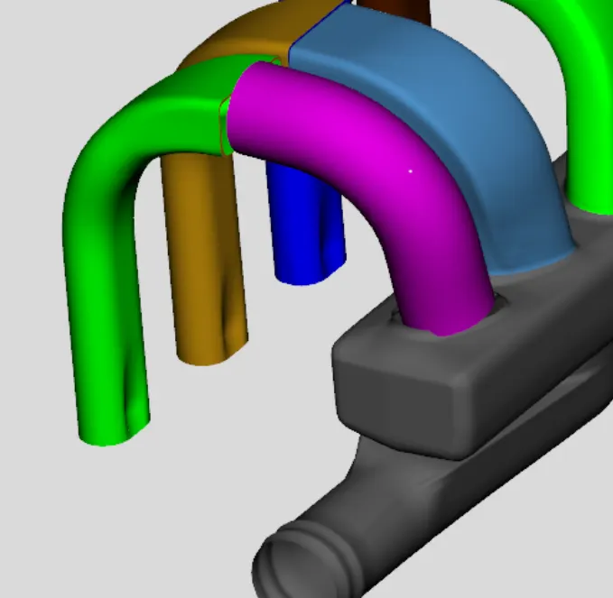
Repeat the above procedures and convert the first section (next to the manifold) of the other 3 runners into flow components.
Once they are all finished, the model should look like the image below
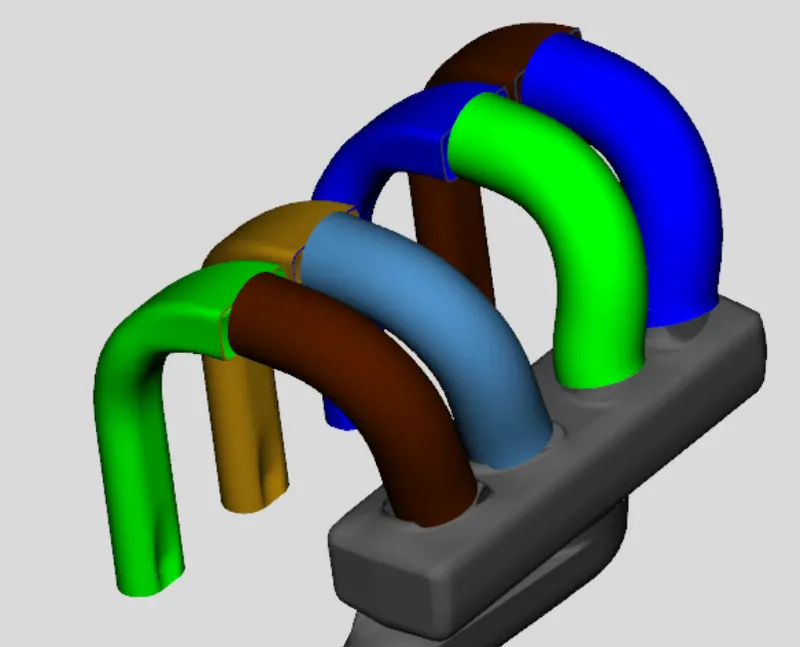
Next we need to convert the end sections of each runner into components. Select the end section of the first runner right click and select Convert Shape to Component. To accurately capture the tapered shape of this section, we need to convert this section into a bent pipe so the inlet and outlet diameters can be different. Therefore, select the Multiple Bends option as bend type. Once again, confirm that the Wall Thickness is set to 1 mm and then click Next.
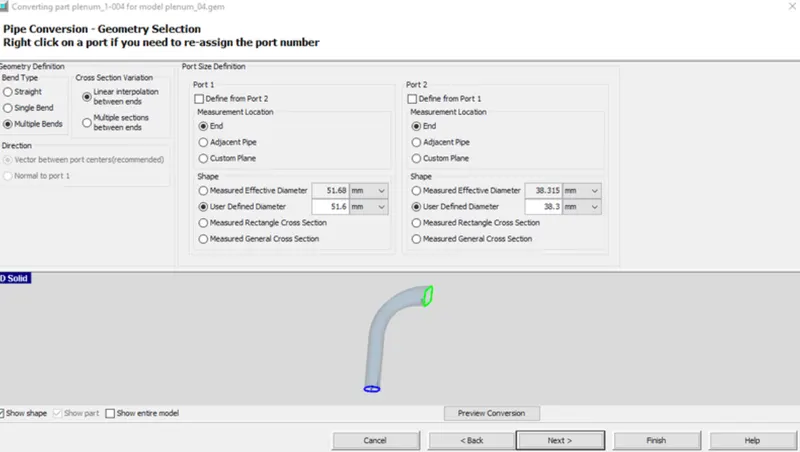
All the geometry is calculated during conversion and the attributes on the main tab are filled in based on the last conversion that was done. Since this component is still part of the intake runner, all of those attribute values are fine. Press the OK button at the bottom of the conversion window to save the part. The model should now look like the image below
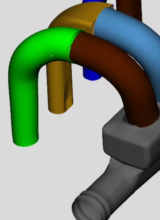
You should notice that there is an extra surface created by the Separate by Curves operation that we performed earlier. This surface is the vertical face of the intake runner where the diameter abruptly changed. Since this surface is not really physical, we can easily delete this surface by simply clicking on it, and pressing the delete key.
Repeat the above procedures and convert the middle section of the other 3 runners into flow components.
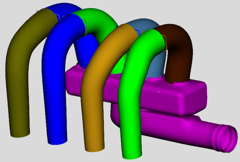
ADDING A CUSTOM CONNECTION:
To add a custom orifice to a flow component right-click on the first section of runner 1 and choose Add Connection. This will open the port connection window, shown in the image below, that allows the selection of which port to add the connection to and what type of connection to use
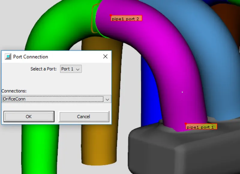
We want to select port 1 (the port at the manifold) and the orifice connection ('OrificeConn'). Click OK and the connection will be added and the appropriate template window will open.
USING PARAMETERS:
With the connection template open. To account for the curved entry we want to modify the forward discharge coefficient. Since all 4 runners likely have the same curved entry shape, they should all get the same discharge coefficient. Therefore, define a parameter named [disch_coeff] for the Forward Discharge Coefficient attribute. The component window should now look like the image below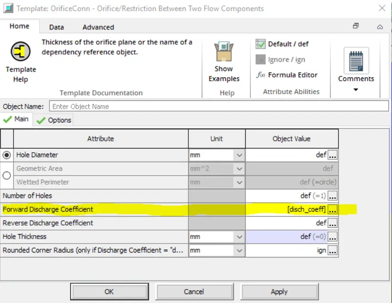
This parameter can be given a value directly in GEM3D by right-clicking on the parameter name and choosing Parameter Values....This will open up Case Setup,
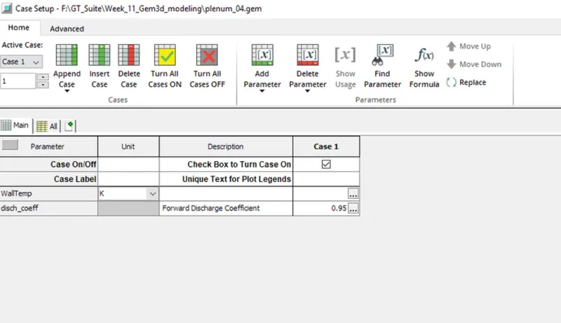
Click OK to Case Setup to save the value and return to the connection window. Click OK to the connection window to save that connection. After a connection is created it is displayed in the graphical window on the appropriate port as a short transparent grey cylinder slightly larger than the parent component.
Repeat the above procedure for the rest of the runners
ADDING A SUBASSEMBLY CONNECTION TO IMPOSE CONNECTION DIRECTION:
The next thing we want to do is specify the end (boundary) connections, meaning the connections that do not connect to anything. To add the subassembly connection right-click on the end section of the first runner component ("run1-2") and choose Add Connection. This will open the port connection window. We want to select port 2 (the port not connected to the rest of the runner) and the subassembly connection ('GEMSubAssExtConn'). Click OK and the connection will be added and the appropriate template window will open.
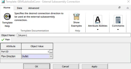
Use "SAconn1" for the name of the component and a Port ID of 1. Set the Flow Direction to "Outlet" since we expect flow to be from the manifold through the runner and out this port. This allows us to control the flow direction at this boundary, while GEM3D can determine the rest of the directions from any specified values. Click OK to save this connection. Repeat this procedure for the rest of the runners using names of "SAconn2", "SAconn3", and "SAconn4" along with Port ID values of 2, 3, and 4.
DIVIDING PIPE SECTIONS WITH AREA CHANGES:
The entrance appears to consist of a pipe section with a round and D-shape, then a 90 degree turn into the manifold. The straight section can be converted into 2 pipes, one representing each effective diameter. Therefore we need to cut and separate these two sections so they can be converted. From the Cutting Planes group in the Convert tab, choose Pipe Normal Cutting Plane.
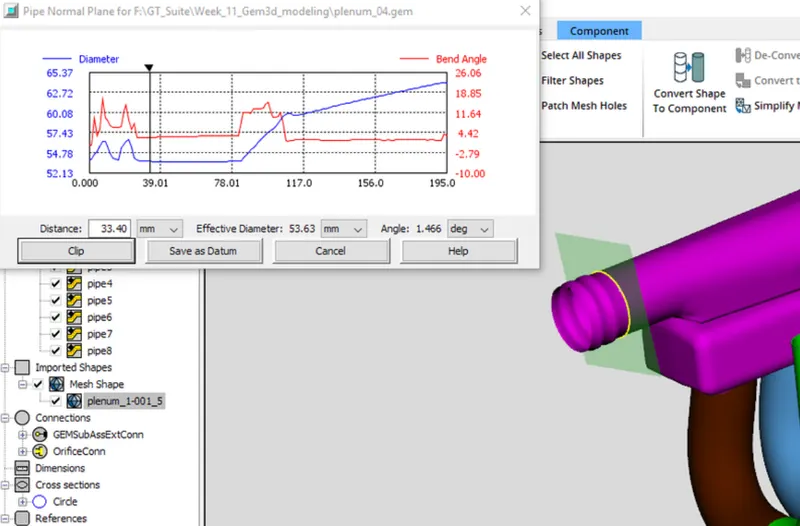
We will convert the end section with the round shape into one pipe, so move the cutting plane by clicking and dragging to a location just before the shape starts to change, using the Pipe Normal Plane window for guidance. Once the plane is in the correct location, press the clip button in the window.
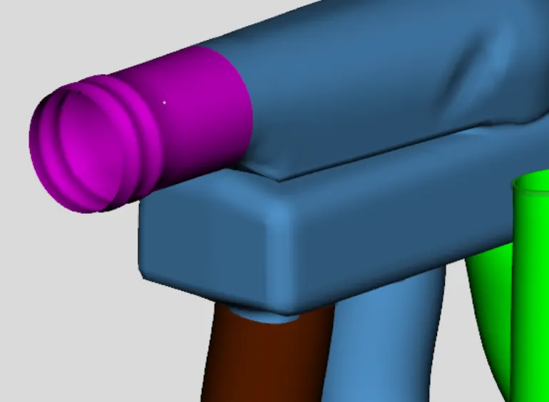
Next, we need to separate the D-shaped pipe section from the flowsplit section entering the manifold. To do this place another pipe normal cutting plane on the D-shaped section and drag it all the way to the end. Once complete, press the clip operation again. The model should now have 2 separate pipe-like sections like in the image below,
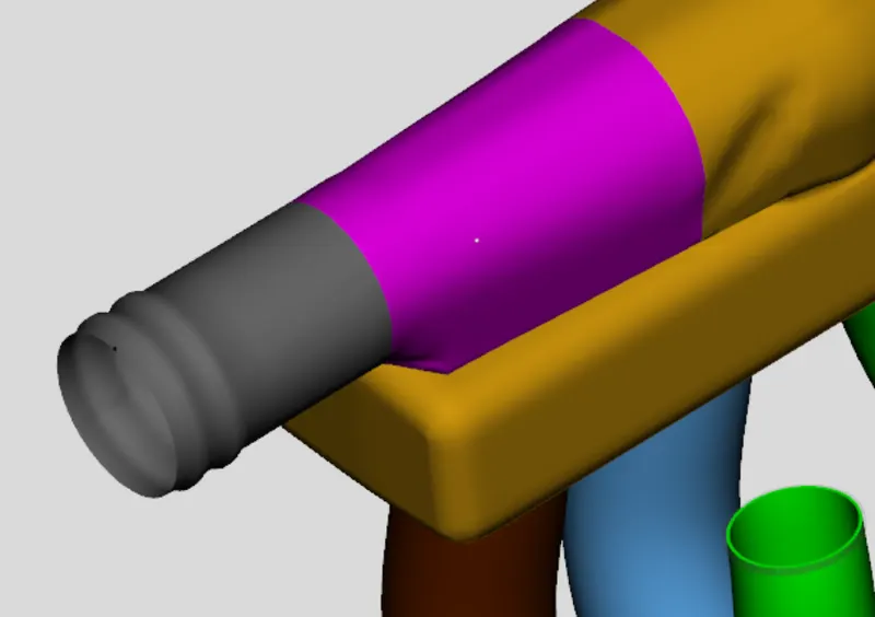
The next step is to convert both of these sections into flow components. Let's convert the round shaped section. Right-click on that section and select Convert Shape to Component. In the pipe conversion – geometry selection window choose the Straight as bend type option. We will model this section as a straight pipe, so for the Diameter for cross section 2 select the checkbox Define from Port 1. Press the Next button to create the straight pipe. Press Next again and give it a name of "pipe1" and click Finish to save the pipe.
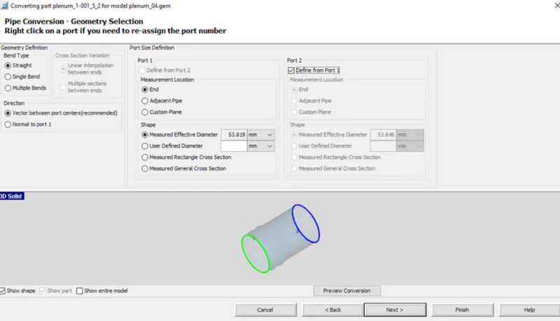
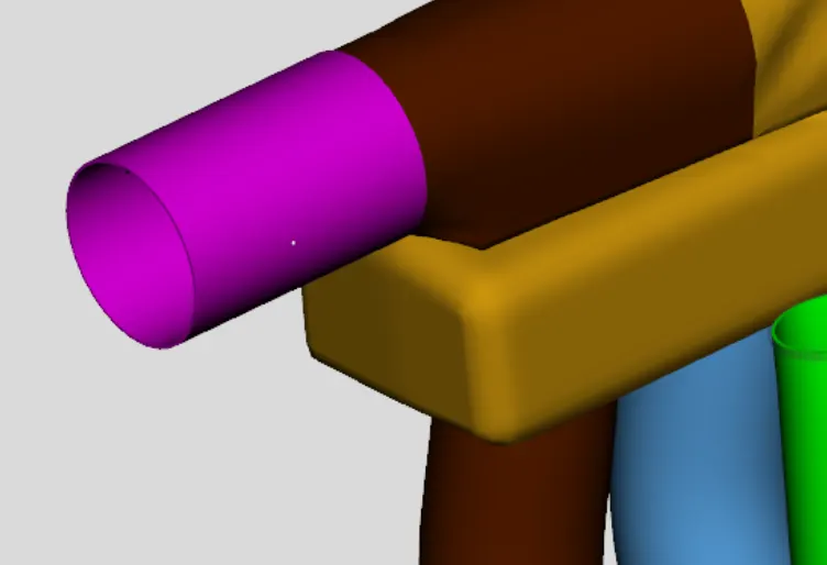
Let's start with the D-shaped section by right-clicking on it and selecting Convert Shape to Component. In the convert mesh window that opens choose the Pipe option. We will model this section as a Straight pipe type with the larger area rather than a taper because the area change is fairly abrupt. Therefore, for the Diameter for cross section 1 select the checkbox Define from Port 2. Press the Next button to create the straight pipe. Press Next again and give it a name of "pipe2" and click Finish to save the pipe.
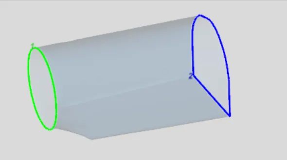
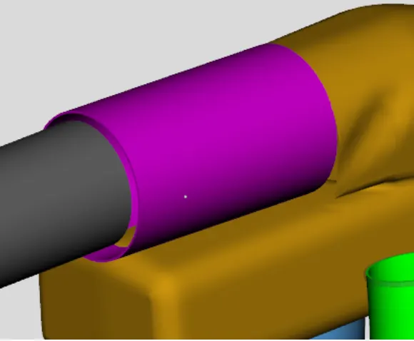
After finishing the conversion of these 2 pipes, the model should look like the image above.
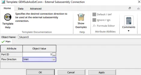
Now we want to specify a subassembly connection on this last pipe since it has an end boundary. To do this right-click on "pipe1" and choose Add Connection. This will open the port connection window. We want to select port 1 and the subassembly connection ('GEMSubAssExtConn'). Click OK and the connection will be added and the appropriate template window will open. Use "SAconn5" for the name of the component and a Port ID of 5. Set the Flow Direction as an "Inlet", as shown below, since we expect flow to be toward the manifold from this port. Click OK to save this connection.
MAKING MORE DIFFICULT CUTS:
To begin, we want to create a cutting plane that has an orientation as close as possible to the final orientation. The top of the manifold is pretty close to this orientation, so we will choose 3 points on this surface of the shape. Start by selecting the 3 Points Cutting Plane from the Cutting Planes group in the Convert tab. To place the plane, pick 3 points on the top of the manifold.
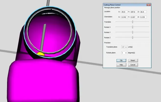
Once the cutting plane is in the correct orientation and location, select the mesh shape to be cut, and press the clip button in the control window. Take a look at the separated components. If the cut went through any port opening of the shapes, then the conversion will not work. If you notice this, you can use the Merge Shapes feature available in the Shape Operations group in the Convert tab.
CONVERTING SECTIONS INTO GENERAL FLOWSPLITS:
Now that the entrance to the manifold is separated, we can convert it into a flow component. To do this, right-click it and select Convert Shape to Component. This will open the convert mesh window. The first thing we need to do is select Flowsplit from the select the conversion geometry options on the right side.
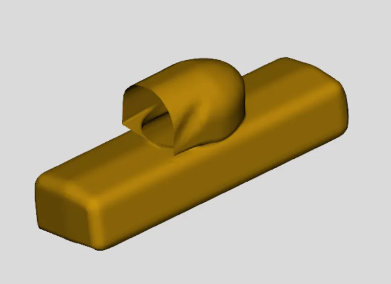
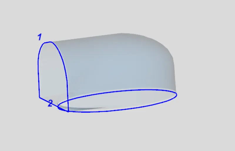
Click on Next again and a flowsplit using the exact geometry of the mesh shape will be created and drawn in the graphical window for comparison. The converted component is shown in the bottom. The conversion window should then look like the image below
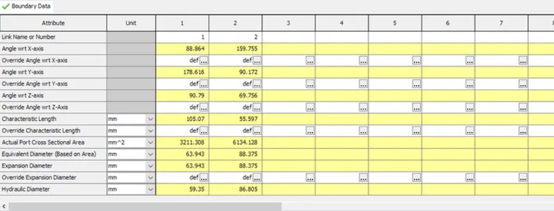
To finish click Next and give the component a name of "man1" and click the Finish button to save the conversion and close the convert mesh window.
DIVIDING A LARGE VOLUME INTO SMALLER SECTIONS:
The first step is to use a cutting plane to cut off the first end section toward the first runner. Enable the cutting plane by selecting 3 Points Cutting Plane from the Cutting Planes group in the Convert tab.
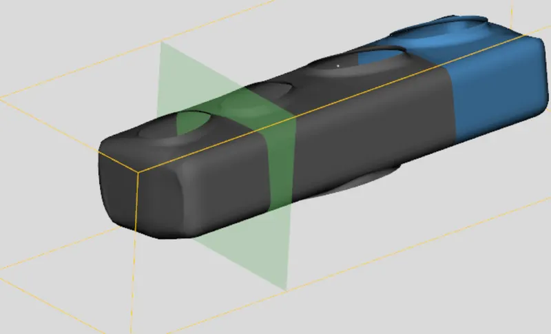
Now that the cutting plane is in the desired location, we need to select the manifold section so that it will be cut. Finally, click the clip button from the Plane Control window. This will separate the end from the manifold creating 2 mesh shapes.
RESTORING A CUTTING PLANE:
We need to make one more cut between the 3rd and 4th runners to finish dividing the manifold. Rather than picking 3 points again, we can restore the last used cutting plane. To do this, select Restore Cutting Plane from the Cutting Planes group in the Convert tab. This will place a cutting plane at the same location and orientation as the last one used and open the control window
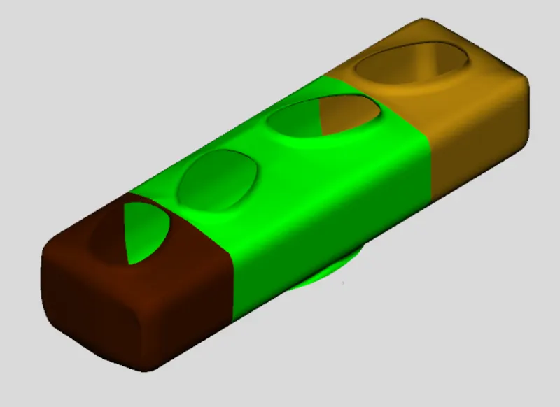
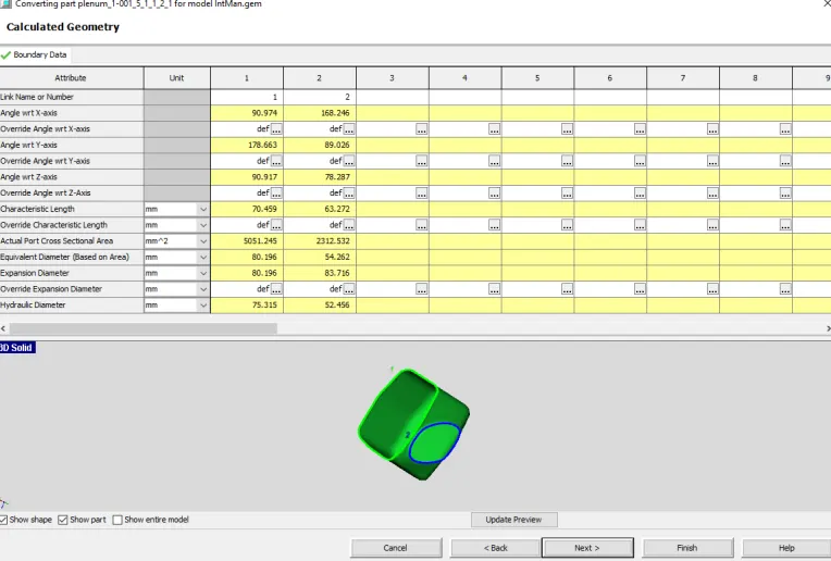
Now that the manifold is divided, we can convert each section into a flow component. Select the end section near runner 1, right-click and select Convert Shape to Component. Select Flowsplit from the select the conversion geometry pane. Upon changing this all open ports of the mesh shape will be identified and assigned a port number, which will be shown in blue in the graphical window. Since flow is expected to enter from the side rectangular port, make sure that is assigned port number 1. If it isn't, click Exclude All Ports and individually add them back in the correct order. With the correct ports identified, click Next twice to convert and create the flowsplit. The conversion window should now look like the image below.
DETERMINIG ORIENTATIONS DURING CONVERSION:
Next, we will convert the center section into a flowsplit. Right-click on it and select Convert Shape to Component. Select Flowsplit from the select the conversion geometry pane.
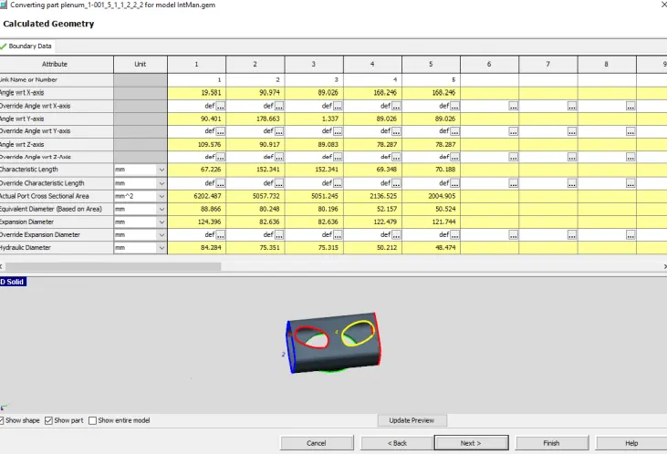
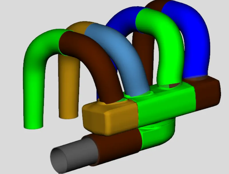
With all the mesh shapes now converted to flow components, the model should look like the image below.
ADDING FLOW CONNECTIONS:
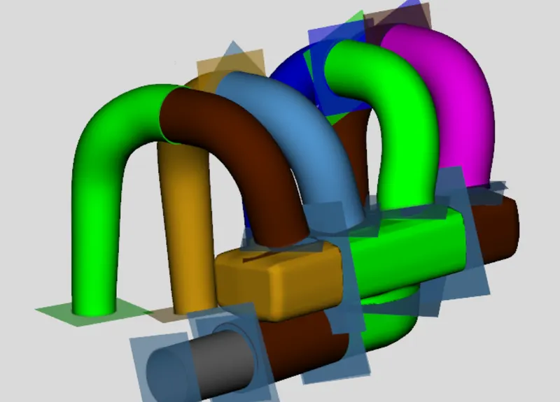
You will notice that during the process of converting meshes to components, we created several pipes which do not align perfectly. To do this, select Flow Connection > Flow Connection from the Connections group under the tab Flow. This will show available surfaces for adding flow connections, as shown below. To join the runners together, click on the flow connection face at the end of the first intake runner, then click on the flow connection face at the end of the second intake runner. The sections should join together, as shown in the screenshot below. Join the other three runners together as well to form the manifold as shown in the screenshot below. You will notice that some of the runners are positioned slightly differently than before. This is acceptable, as the geometry of the flow volumes have still been maintained.
FINAL MODEL:
After completing the above process the final model will looks like this,
DISCRETIZATION:
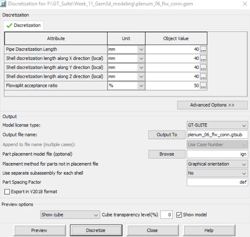
Now that the model consists entirely of flow components, we can discretize the model. To discretize a model, select Export GT Model from either the Home tab or the toolbar. This will open the discretization window that contains the available discretization options. Let's use a pipe discretization length of 40 mm and make sure the output file name is "IntMan.gtsub". Once these are correct, we need to choose an orientation for the model. When GEM3D discretizes the model, it will need to place each component on a 2D map in GTISE. It will do this based on the current graphical orientation of the model by trying to match the parts placement. Since the GEM3D placements are 3D and the GT-ISE map is 2D, the orientation must be carefully chosen as some orientations will result in messy model files. Rotate the model to an orientation with the entrance pointed down and the runners to the right, as shown in the image below
Once the model is in this orientation, click the Discretize button and GEM3D will create a GT-SUITE model file (.gtsub). You will get a message saying the discretization completed successfully. Press the Open in GTise button to open the newly created model file in GT-ISE. The model file map will look like the image below. Notice how the parts are placed on the map to match the 3D placement. If the map placement is not very good, it is very easy to go back to GEM3D, rotate the model to a new orientation, and discretize the model again.