Week-11 Challenge: Braking
Ans-1) In electric vehicle is require by vehicle for acceleration as well as deacceleration of vehicle also. as we require to stop vehicle in stipulated time, we cannot allow vehicle to stop as per it inertia value, for stopping vehicle we require to apply brake. Braking of vehicle require to deaccelerate vehicle to lower speed within a give time.
Suppose we have UDDS cycle:-
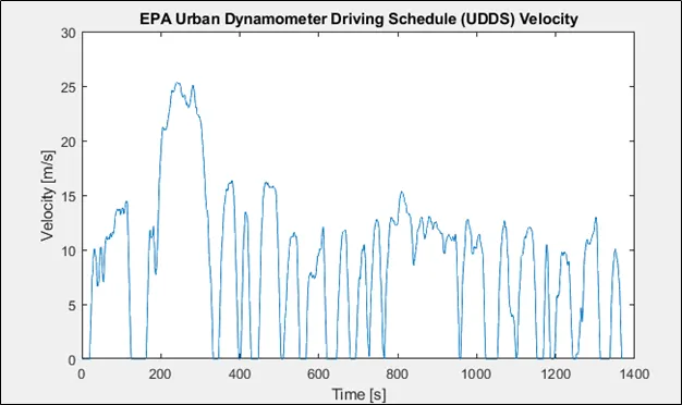
We can overve in this test cycle vehicle needs to stop in given time at some instance also for this we will apply brakes. We will calculte the power require for braking operation.
Please refer the attached sheet for complete calculation deacceleration energy require in UDDS cycle.
1) to reduce speed form 80 to 40 kmph in 20 sec = 292KJ
2) To reduce speed from 0 to 10 kmph in 560 KJ
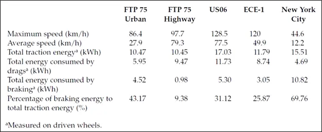
Ans 2) The torque-Speed characteristic of motor is not exact same in the vraking and motoring region.
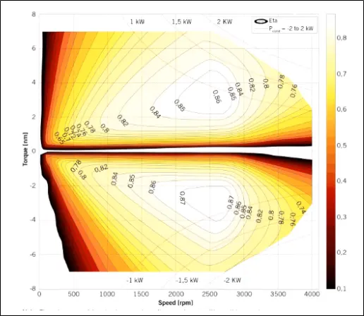
This is torque-speed plot of motor with efficiency.
We can see that, at the time of accelerating vehicle at starting the maximum torque available motor is operating at constant torque region, in that motor will have maximum torque available, but as motor starts deaccelerating motor characteristics are shifted towards braking region, in this we don't have max torque available for braking as motor is already running at higher speed.
Due to this operation, electric motor can't develop braking torque at high speed similar to starting
Electrical and mechanical braking systems can are coordinated by using Brake startegy subsystem
1) Serial braking strategy
2) Paralled braking strategy
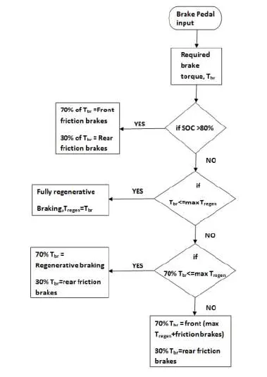
Implementation of serial braking strategy
Once the brake pedal is pressed and depending on the level of depression, a brake torque is sent. Now this brake torque passes into the brake control strategy block. Here, firstly it is checked if battery state-of-charge is below 80% which is set as the maximum permissible level of charge. If that condition is satisfied, there the battery is reharged. The brake torque requested is compared to the maximum regenerative toque limit of the motor-generator. If the overall brake torque requested is less than or equal to the maximum regenerative torque, then the vehicle brakes purely on regenerative torque and the battery is charged. The amount of charge ultimately put independs also on the motor-generator operation efficiency and the battery charging efficiency. if the ovealll brake torque requested is grater than what the motor-generator can provide, then the friction brakes kick-in. Now since the vehicle is front driven, it is checked if the total brake torque requested form front is less than or equal to mazimum regenerative troque capability of motor-generator. If yes, then front braking is provided purely by regeneration and rear by friction. Once the total brake torque request increses futher, then front friction brakes comes into play in combination with rrear friction brakes and font regenerative braking, to statisy the overall brake torque demand. This has been repressented in a hart manner.
Parallel Braking:-
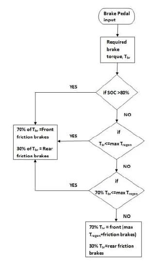
Once the brake pedal is applied and a desired overall brake torque request is sent form the driver block. This brake torque on passing through the brake control strategy ets divided between regeneration and friction braking at all times. the strategy is so modeled with the comfort and braked pedal feel in mind. As a parallel regenerative braking is an add-on to the conventional systems, it is devoid of any integrated control. So to make the transition and co-performance of regenerative braking with friction smooth, it is assigned in such a way that, there is a clear divison vetween the amount of brake torque that will be achieve fromregeneration and friction braking. On application of brakes and in keeping with the design of the motor-generator, it is desined to operated generator in a constant generator torque region. Motor-generator can provide a maximum of 322Nm of generator troqure at or under the base speed. The generator is scaled such that the base speed of the generator corresponds to a velocity of 124, whihc is the maximum speed limit on most highways. Hence regeneration works, as long as the vehicle is braking from a peed of under 124 and the requested braking torque on the front driven wheeels, after the front-rear brake split is greater than or equal to maximum generator troque. if theat condition is satised, then regenerative and friction braking operates in tandem else it's just the friction brakes at the driven and non-driven axle. This has been represented in a row chart manner.
Ans 3)
Syntax
clear all;
close all;
clc;

Torque= linspace(1,250,250)             %Input Torque
Speed= linspace(1,1000,250)             %Input Speed
[w,T]= meshgrid (Speed,Torque);         %Converting to 2D array

Kc= 0.3;         % Coppper loss constact
Ki= 0.009;       % Iron loss Constant
Kw= 0.00005;     % Windage loss constat
C=30;            % constant loss

Pout= w.*T;         %Output Power
C_loss=Kc*(T.^2);   %Copper loss
I_loss=Ki*w;         %Iron loss
W_loss=Kw*(w.^3);    %Windage loss

Pin=Pout+C_loss+I_loss+W_loss+C;    %Input power
eff=Pout./Pin


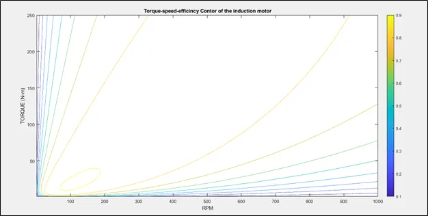
contour(Speed,Torque,eff)
title('Torque-speed-efficincy Contor of the induction motor');
xlabel('RPM');
ylabel('TORQUE (N-m)');
Syntax Explanation:-
In this program we are plotting speed Vs torque characterisitic with the efficiency values. For this, first we are defining speed and torque values of motor.
then as we need to draw a contour, we convert this ID array to 2D array using MESHGRID CMMAND.
Then we are defining the Cu constants for losses, like Cu loss constants, iron loss constant and windage loss constant.
Pi = Pout+Kc*T^2+Ki*w+Kw*^3+constat loss
using this formula, we calculate the efficiency and then plot the contour.
Result