Week-11 Challenge: Braking
- For a defined driving cycle, calculate the energy required for braking.
- Why electric motor can’t develop braking torque at high speed similar to starting? How electric and mechanical brakes are coordinated?
- Make a MATLAB program which plots contour of given motor speed, torque and efficiency values. Attach the code as a .m file attach a screenshot of all the plots.
Answer:
01.
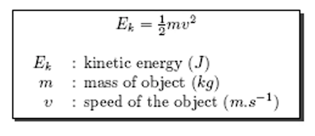
Under the condition of braking, some amount of energy is required to do the same as that of energy required for accelerating the vehicle. Hence to calculate energy, we use the acceleration energy equarion,
Graphical Representation of drive cycle:
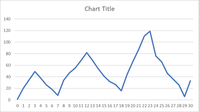
From the above drive cycle, braking scenario have been identified to calculate the energy required for braking:
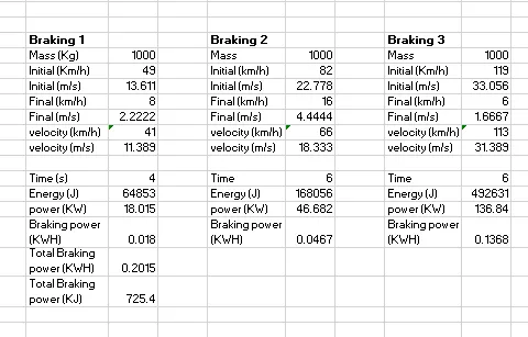
Total energy required for braking 725.4 KJ.
02.
This are the type kinectic energy recovery system that transfer the kinectic energy of an object into potential or stored energy to slow down the vehicle and as a result to increase the fuel efficiency.There are multiple methods of energy conversion in Regenerative Braking System including spring, flywheel, electromagnetic and hydraulic. More recently, an electromagnetic-flywheel hybrid.
They are are installed along the drive train or fitted to the drive wheels of a vehicle where they inhibit the motion of the wheels using magnetic fields or mechanical torque. These methods of motion inhibition allow energy to be generated under braking, as opposed to friction brakes which simply waste away energy to slow the vehicle by turning the kinetic energy into thermal energy.
Regenerative Braking system can improve fuel consumption and reduce the overall braking load taken on by the vehicles friction brakes, reducing the wear on the brake pads. In HEV and EV the transmission of the car is set up such that when the driver applies the brakes, the electric motor reverses itself and applies a resistance to the wheels rather than power, this resistance applied to the wheels is then put through the electric motor where it is used to recharge the batteries.
Regenerative braking allows electric vehicles to use the motor as a generator when the brakes are applied, to pump vehicle energy from the brakes into an energy storage device. Regenerative braking is an effective approach to extend the driving range of an EV.
- The regenerative braking torque cannot be made large enough to provide all the required braking torque of the vehicle as it might lead to the deterioration in stability of the vehicle. Also as compared to the torque values of acceleration torque of motor is much higher than decceleration torque.
- At high speed, the motor might be in its constant power region which causes less values of torques produced and this limits the amount of braking torque that is used for regeneration. Hence the peak vlaue of accleration torque and braking torque are not equal.
There are 2 different control strategies for Braking Combinations:
- Series Control Strategy
- Parallel Control Strategy
Series Control Strategy:
- a combination of friction-based mechanical braking system with a regenerative braking system that transfers energy to the battery with an integrated control, which distributes the required braking force between the regenerative braking system and the mechanical braking system.
- Series Startegy could give an increase of 15-30% in fuel efficiency and has more consistent braking due to good torque blending capability.
Parallel Control Strategy:
- combination of mechanical and the regenerative braking system, operated simultaneously without an integrated control.
- The regenerative braking force is added to the mechanical braking force which cannot be controlled.
- The regenerative torque is determined by considering the motor capacity, battery SOC, and vehicle velocity. The regenerative braking force is calculated from the brake control unit by comparing the demanded brake torque and the motor torque available.
Application of Braking Combination : EDIB (Electric Driven Intelligent Brake) in NISSAN LEAF
- EDIB allows and controls optimization of the regenerative brake and regular friction brake (hydraulic brake).
- The system produces an adequate braking force keeping energy regeneration increased as much as possible.
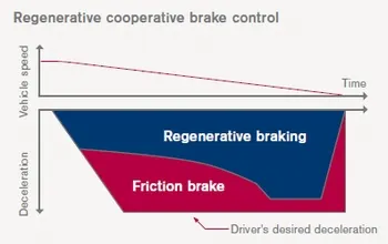
- At higher speeds, a combination of regenerative and friction braking is applied.
- At lower speeds, regenerative braking is given a higher proportion for maximised energy conversion.
Limitations :
There is a limitation due to the maximum recharging rate of the circuit and the capacity of battery, the braking force from an electromagnetic is always limited
How are electric brakes and mechanical brakes co-ordinated?
In electric vehicles, two types of braking systems are used electric brake system and mechanical brake system.
Electric Braking System: In electrical braking, the winding of the motor is used to produce a braking torque. A braking torque is developed during the braking operation. This braking torque opposes the motion of the rotating member or shaft. This is achieved by suitably changing the electrical connections of the motor. The motor operates on a speed–torque characteristic, depending upon the method of braking employed.
Mechanical Braking System: In mechanical braking, the frictional force between the rotating parts and the brake drums produces the required braking. To achieve this, mechanical equipment, such as brake linings and brake drums, are required. Whether electrical or mechanical, the braking of the drive should stop the motor at the specified point of time and position.
The electric braking system used in EVs and HEVs is regenerative braking. This method uses the motor as a generator during braking, developing a retarding torque, which acts on the running motor and halts it. The kinetic energy and potential energy, minus the losses of the motor are returned to the mains and the motor runs at a constant speed. Thus, regenerative braking eliminates the tendency of the load to accelerate the motor.
Mechanical braking systems used can be either disc or drum brake system. Where in case of a disc brake system friction pads rub against a disc when the brake pedal is applied and the kinetic energy is converted to heat and slows the vehicle down. In a drum brake system a set of brake shoes which are the friction materials press against a drum.
Since the braking torque is very less at high speeds, mechanical brakes are applied to slow down the vehicle. As the motor reaches the constant torque region the regenerative braking system takes effect where the motor acts as a generator and the negative torque produced charges the battery pack.
03.
clear all
close all
clc

% SPEED ARRAY
w = linspace(0,1000);

% TORQUE ARRAY
T = linspace(0,300);

% LOSS COEFFICIENTS
kc = 0.18;  % COPPER LOSSES
ki = 0.006; % IRON LOSSES
kw = 0.000015; % WINDAGE LOSSES

% MESHGRID
[X,Y] = meshgrid(w,T);
copper_loss = (Y.^2)*kc;
iron_loss = X*ki;
windage_loss = (X.^3)*kw;
K = 20;
output_power = X.*Y;
input_power = (copper_loss)+(iron_loss)+(windage_loss)+(output_power)+K;
Eff = (output_power)./(input_power);
n = linspace(0.7,0.95,10);
contourf(X,Y,Eff,n);
title('SPEED TORQUE CHARACTERISTICS')
xlabel('SPEED rad/s')
ylabel('TORQUE N-m')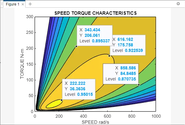
The contour plot for a motor with defined constants are plotted in the defined Speed Vs Torque Region based on efficiency. As the Speed increases the efficiencies of the motor will be reduced.
The color bar is used to know the efficiency based on the color of shading in the plot ranging from 0.87 to 0.95