Week-11 Challenge: Braking
Week-11 Challenge: Braking
Q.1) For a defined driving cycle, calculate the energy required for braking.
Braking is the process of controlling the velocity of an object by inhibiting its motion. An object in motion possesses kinetic energy and to bring the object to a stop this kinetic energy must be removed. Removing the kinetic energy can be accomplished by dissipating the energy to the atmosphere through friction or by converting it into another form of energy. The most common type of braking is a mechanical brake which inhibits motion through friction brake pads. A mechanical brake applies a friction force to convert the kinetic energy of the vehicle into thermal energy which then dissipates into the atmosphere. Braking systems which don't use friction are referred to as regenerative braking systems (RBSs). In RBSs, the kinetic energy is converted into other forms of useful energy, which can be stored for later use, increasing fuel efficiency.
The equation for kinetic energy from braking is given as,
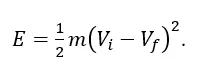
Where,
m = Mass of the vehicle in Kg.
Vi = Initial speed of the vehicle in m/s.
Vf = Final speed of the vehicle in m/s.
The drive cycle is prepared in excel sheet based on speed in km/hr & time in seconds. The chart is plotted Speed Vs Time in Excel sheet.
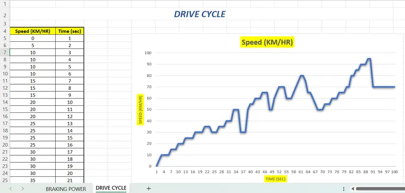
From the drive cycle 6 braking points were obtained.
The mass is set at a constant 1500 Kg.
The energy required for braking is given in the table below.
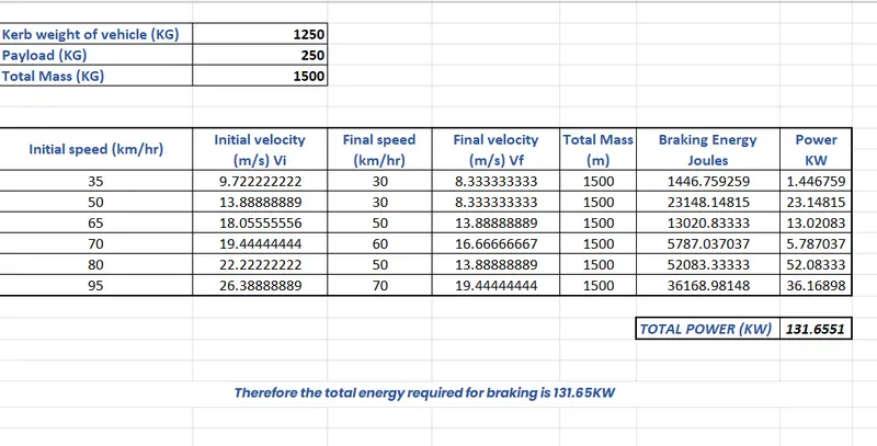
Therefore the total energy required for braking is 131.65 KW.
The excel sheet file of the drive cycle and braking data excel sheet is attached.
Q.2) Why electric motor can’t develop braking torque at high speed similar to starting? How electric and mechanical brakes are coordinated?
With the modern traction equipment, Electric Vehicles can easily achieve the desired acceleration. However, if the stopping system or braking system of the Electric Vehicles fail, it will cause a great disaster. Therefore, braking system of Electric Vehicles is very important. In this let's understand how mechanical breaking differs from electric breaking and which one is more efficient.
Mechanical Braking-:
Mechanical brakes are applied by brake shoes which are pressed with force against the wheel of the train. In mechanical braking, the braking force is generally produced by means of piston-cylinder arrangement. The movement of the piston is transmitted to the brake shoes through a system of levers.
Electrical Braking-:
In electric braking, the kinetic energy of the moving parts of the motor is converted into electrical energy which is either dissipated in a resistor or returned to the supply source. Thus, electric braking is a system of braking in which a braking action is applied to an electric motor by causing it to act as a generator.In electrical braking, the winding of the motor is used to produce a braking torque. A braking torque is developed during the braking operation. This braking torque opposes the motion of the rotating member or shaft. This is achieved by suitably changing the electrical connections of the motor. The motor operates on a speed–torque characteristic, depending upon the method of braking employed.
Types Of Electric Braking-
1.Regenerative Braking (Energy is fed back to source)
2. Dynamic Braking (Energy is dessipated in resistor)
3. Plugging or Reversing Braking (Phase changing of motor RYB to RBY which causes change in phase sequence which ultimately causes change in direction of motor. But has severe impact on windings.)
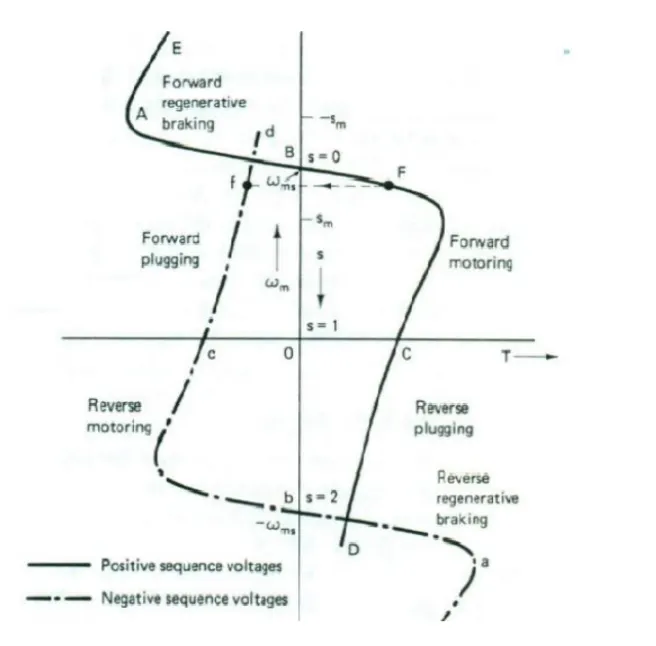
- The speed-torque curves obtained by the reversal of the phase sequence of the motor terminal voltages are also shown by dotted lines. With a positive sequence voltage across the motor terminals, the operation above synchronous speed gives the regenerative braking operation (portion BAE). Similarly, with a negative sequence voltage across the motor terminals, regenerative braking is obtained for speeds above the synchronous speed in the reverse direction (portion bae). In regenerative braking, the motor works as an induction generator, converting mechanical energy supplied by the load to electrical energy, which is fed to the source. Thus the generated energy is usefully employed.
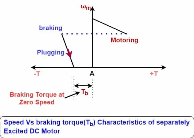
- When we press the brake pedal, we cut off the power supply to the motor and now the motor will be in the rotation due to it inertia. As this rotation is happening inside the magnetic field a Back Emf is generated which produces a negative Torque and that used as the brakes to reduce the vehicle speed. Also the current flows in the reverse direction, Using a Bi-directional Inverter we can store the current back into the battery.
- During the initial low speed, the Torque is high which is the constant Torque region. As speed builds up, after the Critical speed point the torque gradually decreases which is known as the constant Power region.So during high speeds, the motor will be at constant power region, and while braking, due to the high speed of the motor the negative Torque produced will be less.
- But while starting the motor, the speed will be very less and at this stage, the motor will be operating in a constant Torque region and most of the torque is used to increase the kinetical energy of the load (and motor). But when the speed is already high and no extra load is applied it is not possible to increase the torque.
There are other reasons like Battery Limitations due to which we cannot get High braking torque also the rate of discharge is always higher than the rate of charging due to the battery's chemical compositions.
There are two ways of applying the combination of brakes and they are classified as,
1.Series - Regenerative braking and Frictional braking are applied one after another
Series regenerative braking is basically based on the combination of friction-based adjustable braking system that transfers energ to the electric motors and batteries under an integrated control strategy. The overall design of serial regenerative braking is to estimate the deceleration required and distribute the required braking force between the regenerative braking system and the mechanical braking system. The serial braking system requires brake by wire system and has a more consistent pedal feel due to good torque blending capability. It can increase the efficiency by 15-30%.
2. Parallell - Regenerative braking and Frictional braking are applied at the same time . A parallel braking system is basically based on the combination of a friction-based system and the regenerative braking system operated in tandem without an integrated control. The regenerative braking force is calculated from the brake control unit b comparing the requested brake torque and the motor torque available. A parallel regenerative braking system requires more work in achieving good torque blending. This system can increase the efficiency by 9-18%.
One of the classic examples of coordination of these two brakes in the EDIB( Electric Driven Intelligent Braking) develop for the NISSAN leaf
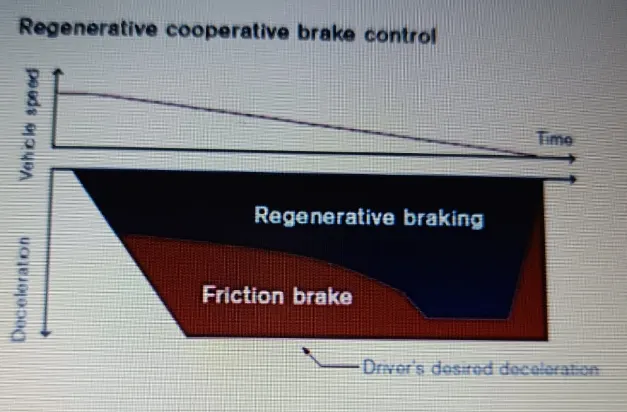
Electric Driven Intelligent Braking develop for the NISSAN leaf is a combination of Hydraulic brake or mechanical brake along with the Regenerative braking. Parallel braking technique is employed where at initially at higher speed you have both regenerative braking & friction braking. And whenever speed of vehicle reduces at low speed you get higher torque by motor. At lower speed you get higher braking torque. Therefore as can be seen from above figure percentage sharing at low speed will be different i.e % regenerative braking will be higher than % frictional braking. At higher speed there will be combination of both regenerative & friction braking.
Comparision Between Mechanical braking & Electrical Braking-:
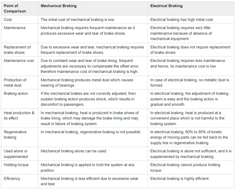
The following table highlights the points that differentiate an electrical braking system from a mechanical braking system
Q.3) Make a MATLAB program which plots contour of given motor speed, torque and efficiency values. Attach the code as a .m file attach a screenshot of all the plots.
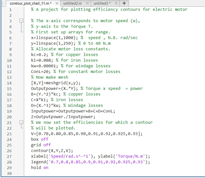
MATLAB Script-
Explanation-
- The program starts with assigning Input of Speed and Torque in an array using 'linspace' Command and allocate Constant Values for four losses(Copper Loss, Iron Loss, Windage Loss and Constant Motor Loss)
- Mesh the Speed and Torque values using 'meshgrid' command. Basically it makes the size of both array equal.
- Calculate the Output Power by multiplying Speed and Torque values.
- Calculate Copper Loss, Iron Loss, Windage Loss using those formulas.
- Calculating Inputpower by adding Output Power and Four Losses(Copper Loss, Iron Loss, Windage Loss and Constant Motor Loss).
- The ratio of Output Power and Input Power we can get the Efficiency.
- Now Set the Efficiencies for which a contour will be plotted. The range of contour efficiency is to plot Plot the Contour Efficiency using 'contour' command and plot Speed,Torque,Efficiency and V.'contour(X,Y,Z,V)'
Results-
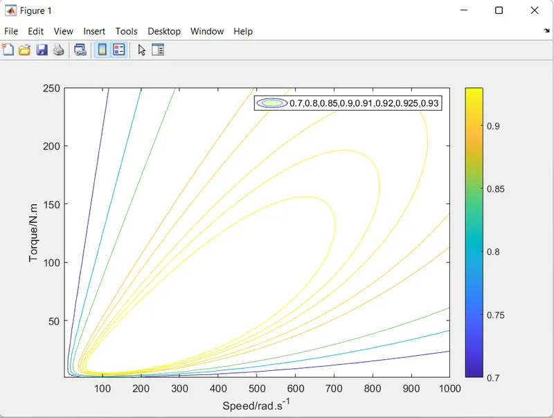
Here Blue line indicates the Efficency and Yellow line indicates Outputpower.
From the plot it can be observed that the speed and torque varies as the efficiency increases. This is due to the motor losses that occur. The dark blue line represent the contour 70% efficiency and the bright yellow line represents the contour 93% efficiency.
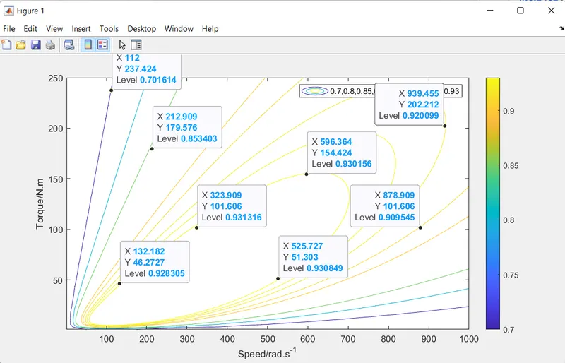
For example at 70% efficiency, the torque reaches it's peak value of 250 N-m when the vehicle is a very low speed but the torque decreases significantly as the speed increases for the same efficiency. And at a motor efficiency of 93% the speed and torque required is much less compared to an efficiency of 70%.
Greater the motor efficiency, lower speed-torque combination is required to overcome the motor losses.