Week-11 Challenge: Braking
1.Energy required for braking.
Deceleration conditions are similar to acceleration conditions. Acceleration increase in speed and deceleration is a reduction In speed. So similar way to calculate braking power.
During braking also required the same amount of power required for acceleration so applying those standard equations we can calculate the energy for braking by the following formula :
Breaking Energy = 0.5*M*V^2
Where M= mass of the vehicle.
V= Velocity.
By this formula, we can calculate the energy in joule
Drive cycle :
I prepare my own driving cycle for this expriment,the excel file is attached with this ans,
The excel calculation makes as belows,
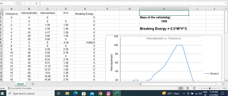
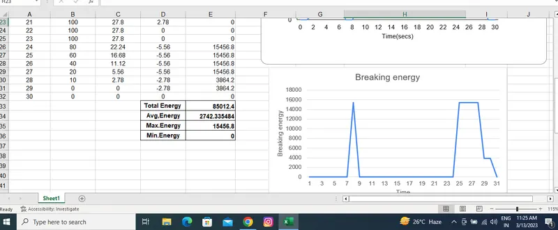
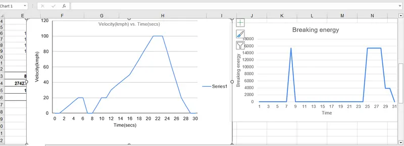
From the calculation we can observe that the energy requried for the breaking of the given drive cycle is 85012.4 Joule
| Total Energy | 85012.4 |
| Avg,Energy | 2742.335484 |
| Max.Energy | 15456.8 |
| Min.Energy | 0 |
2. Electric motor can't develop braking torque at high speed similar to starting, because Braking Torque of an EV Motor is not as high as the Acceleration Torque. Therefore Regenerative braking is cannot happen so effectively that we can get all the power back to the battery.
Electric Motor Braking :
Eectric motor can’t develop braking torque at high speed similar to starting, because Braking torque is applied in the opposite direction of the rotation. We can use a mechanical brake to produce a braking torque. We can also do it electrically.
Regenerative Braking: It is a form of braking in which the kinetic energy of the motor is returned to the power supply system.
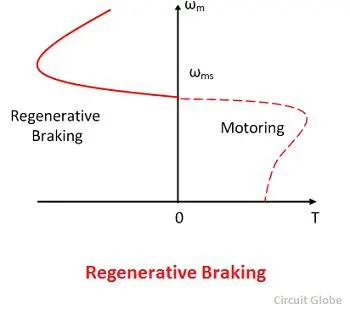
Fig : Speed-Torque Characteristics of Regenerative Braking
Regenerative braking takes place whenever the speed of the motor exceeds the synchronous speed. This baking method is called regenerative baking because here the motor works as generator and supply itself is given power from the load, i.e. motors. The main criteria for regenerative braking is that the rotor has to rotate at a speed higher than synchronous speed, only then the motor will act as a generator and the direction of current flow through the circuit and direction of the torque reverses and braking takes place.
Sometimes after accelerating you can't reach the maximum torque. The reason is that no matter how much the current loop wants to increase current (proportional to torque) by increasing the PWM duty cycle of the power stage, the Vmotor is too close to Vbemf and therefore current can't increase more.This situation does not occur at the beginning of an acceleration because most of the torque is used to increase the kinetical energy of the load (and motor). But when the speed is already high and no extra load is applied it is not possible to increase the torque.
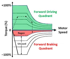
Fig : Acceleration Torque vs Deceleration Torque
Peak Acceleration Torque and Peak Deceleration torque are not equal for Electric Vehicle Motor. So the Peak Torque during acceleration and the Peak torque during deceleration or braking are not equal. Acceleration is usually higher, at low speed we get higher Torque but high speed the value of the torque gets lower. So we cannot say that the motor which is producing 7Nm Torque for Acceleration can also produce -7Nm of Braking Torque. So beacuse we Operating the Motor in Field Weakening region or we are operating the Motor above base speed we must know that the torque is compromised or the torque value is lower. So Electric motor can’t develop braking torque at high speed similar to starting, because Braking Torque of an EV Motor is not as high as the Acceleration Torque. Therefore Regenerative braking is cannot happen so effectively that we can get all the power back to the battery.
3.To plot contour line for a given Motor. A Motor have various types of losses happening inside. The various types of losses are
lot contour line for a given Motor. A Motor have various types of losses happening inside. The various types of losses are
Copper Losses - I^2*R, where R is the Armature resistance and we say that Torque is proportional to Current, this copper loss can be consider as Kc*T^2.where Kc is to take care of resistance of brushes and also take care of flux and its effect.
Copper losses = Kc*T^2
Iron Losses - Iron Losses are nothing but Magnetic losses, which is denoted as Ki*w, where Ki factor is based on the Magnetic field effect. For Permanent Magnets have constant Magnetic field and this Iron losses is based on the value of Ki and this are going to change according to the Speed. At Various Speed have different value of Back EMF and that is going to affect the Iron Losses.
Iron Losses = Ki*w
Windage Losses - This is a Mechanical or friction of Windage losses. This is based on size of shape of Motor and the amount of windage losses that the motor is going to experience.
Windage Losses = Kw*w^3
Constant Losses - This is denoted as C.
Total Losses - The Total Losses are considering the above four losses and denoted as,
Total Losses = Kc*T^2 + Ki*w+ Kw*w^3 + C
All Motors are model as per the above equation of losses. This above equation is not only applicable for Permanent Magnet DC Motor, but other motors as well like induction motor
% Matlab program for contour plot
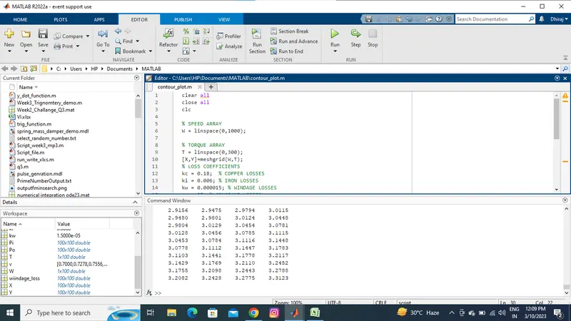
Result :
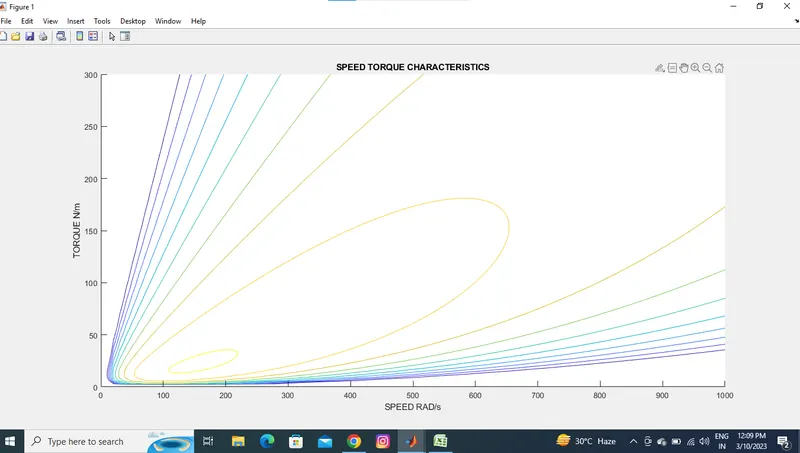
As we see in output we going inside to circle our efficiency get increase and outside it will decrease.