Week-11 Challenge: Braking
Que 1:
Ans:
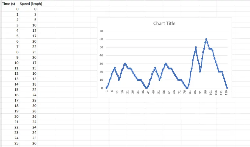
Step 1: Design Drive cycle in excel which is Speed of vehicle in kmph at different time in seconds as shown in figure below
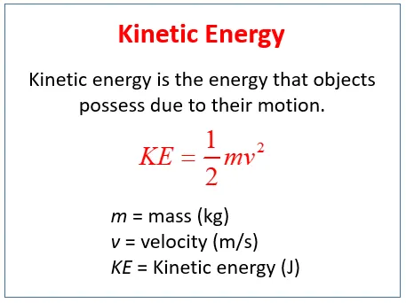
Step 2: Braking Energy is nothing but kinetic energy of wheel which is given by
Step 3: Develop matlab script for calculating braking energy corresponding to given drive cycle using formula of kinetic energy
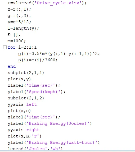
In this script 1st given speed is converted into m/s then energy is calculated in joules using kinetic energy for each speed using for loop
Step 4: Braking energy calculated using script as per driving cycle speed in (m/s) as shown below:
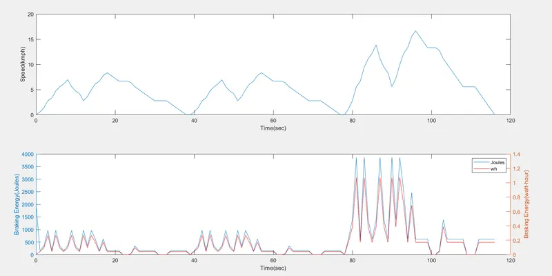
As shown in above result braking energy required more when there is high decceleration in driving cycle
Que 2:
Regenerative Braking of Induction Motor
We know the power (input) of an induction motor is given as.
Pin = 3VIscosφs
Here, φs the phase angle between stator phase voltage V and the stator phase current Is. Now, for motoring operation φs < 90o and for braking operation φs > 90o. When the speed of the motor is more than the synchronous speed, relative speed between the motor conductors and air gap rotating field reverses, as a result the phase angle because greater than 90o and the power flow reverse and thus regenerative braking takes place. The nature of the speed torque curves are shown in the figure beside. It the source frequency is fixed then the regenerative braking of induction motor can only take place if the speed of the motor is greater than synchronous speed, but with a variable frequency source regenerative braking of induction motor can occur for speeds lower than synchronous speed. The main advantage of this kind of braking can be said that the generated power is use fully employed and the main disadvantage of this type of braking is that for fixed frequency sources, braking cannot happen below synchronous speeds.
Regenerative braking is a unique technique that is used in EVs to capture energy that the vehicle has due to its motion or, in other words, its kinetic energy that would have been wasted when the vehicle decelerates or comes to a standstill while braking. By taking a measure of the initial and final vehicle velocity, the amount of kinetic energy that is lost to braking can be calculated.
Urban drive cycles have a considerable amount of acceleration and decelerating periods due to traffic control systems in place around towns and cities, and therefore, when decelerating, significant energy is lost. However, with regenerative braking, this energy can be captured, and ‘waste’ energy can be harnessed and utilized for vehicle propulsion
Peak Acceleration Torque and Peak Deceleration torque are not equal for Electric Vehicle Motor. So the Peak Torque during acceleration and the Peak torque during deceleration or braking are not equal. Acceleration is usually higher; at low speed we get higher Torque but high speed the value of the torque gets lower. So we cannot say that the motor which is producing 7Nm Torque for Acceleration can also produce -7Nm of Braking Torque. So because we Operating the Motor in Field Weakening region or we are operating the Motor above base speed we must know that the torque is compromised or the torque value is lower. So Electric motor can’t develop braking torque at high speed similar to starting, because Braking Torque of an EV Motor is not as high as the Acceleration Torque. Therefore, Regenerative braking is cannot happen so effectively that we can get all the power back to the battery
Electric and mechanical brakes are coordination:
In electric vehicle Electric and mechanical braking combination divided into two types: Series and Parallel braking
Series Braking:
In this type of braking either electric or mechanical brake apply at a time
Parallel Braking:
In this type of braking both electric and mechanical braking are used with proper strategy depends on battery requirement and braking force of driver
Electric Driven Intelligent Braking System:
The braking force is provided with the help of a ECU controlled motor and ball screw arrangement. This means that no direct load on the engine while applying brakes. This means that a motor operated the brake for providing the braking energy. A more controlled and uniform braking force is applied since its ECU controlled, this helps to recover braking losses when a regenerative braking system is used.
Que 3:
Ans:
Develop MATLAB Code for contour plot as shown below:
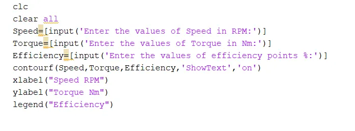
Step1: Take user inputs for speed torque and efficiency data
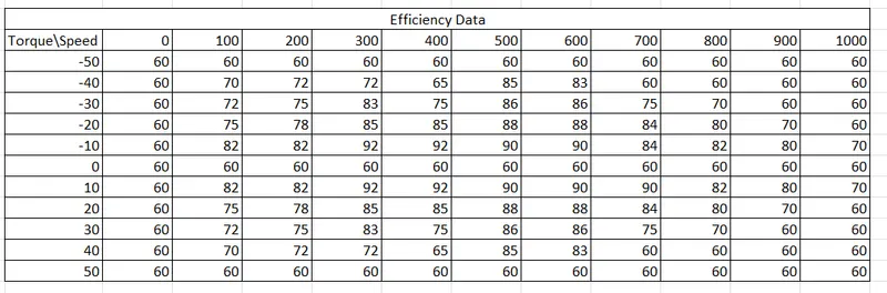
This motor efficiency data is used for reference for ploting contour
Step 2: Contour function in matlab is used in which speed, torque and efficiency data is loaded
Step 3: filled contour plot with colour and show text value for better visualization of plot
Step 4:Results of MATLAB code is as shown below:
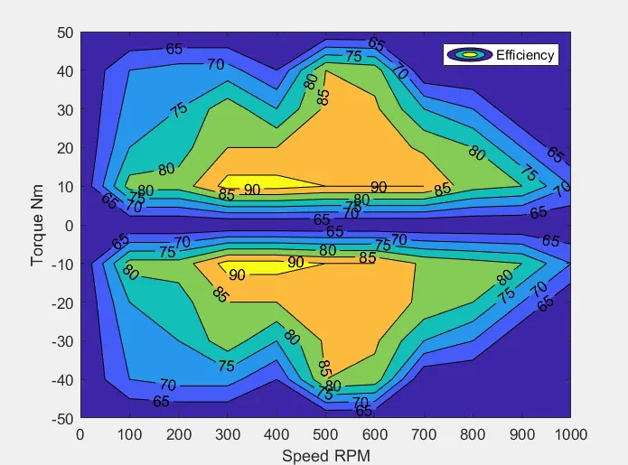
As shown in contour plot high efficiency of 92% is shown by yellow colour which at around based speed of motor
lowest effieciency of motor is 60% as shown by blue colour which is non-operating zone of motor
From this contour plot we can concluded that our motor operating region id between 300-800 RPM with torque of 10-40Nm
Using this data we can select proper gear box for electric vehicle so that motor operated in efficient zone
.m file, efficiency and result fig attached for reference