Week-11 Challenge: Braking
1............................
The braking performance is one of the most important concerns in vehicle safety. In urban area driving, a significant amount of energy is consumed in braking. Electrification of vehicles makes it feasible to recover some of the energy lost in braking. A hybrid braking system was developed to ensure the efficient braking of the vehicle and recovering the braking energy. The design and control objectives of such a hybrid braking system are to ensure sufficient braking force to quickly reduce the vehicle speed, properly distribute the brake force to the front and rear axle, and also recover as much braking energy as possible. So understanding of braking energy of a driving cycle is important. Now, it is also important to mention that braking energy also depends upon the type of driving cycle
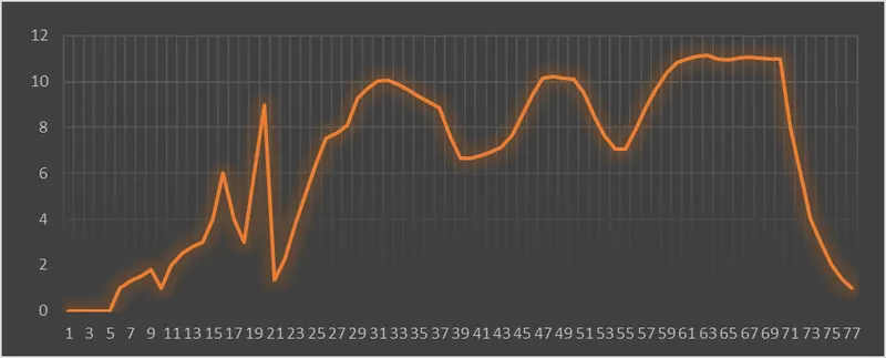
drive cycle
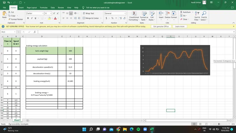
power calculation using an excel calculator we got the power in kwh = 42.48
for ev with mass =600kg and velocity of 11.9 and deceleration time of 10sec
an excel file is attached below for reference
2...............................
The electric motor can't develop braking torque at a high speed similar to starting because once the electric supply is pulled off from the motor, it acts as a generator and due to the flux weakening effect of the electric generator, the generator produces low torque as expected.
At High speed, the torque will be less & operates at a constant power region hence it is difficult to bring the vehicle to rest or decelerate immediately. The peak acceleration torque is greater than the peak deceleration torque. Hence Braking torque of the EV motor is not as high as the acceleration Torque.
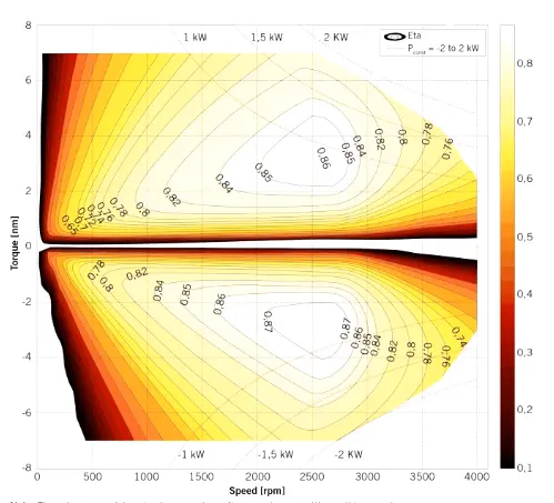
in this, the torque is positive in the first quadrant and negative in the second quadrant whereas speed is positive in both the quadrant
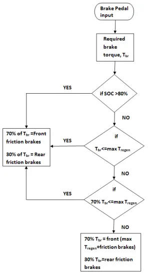
(b)---Electrical and mechanical braking systems can are coordinated by using a Brake strategy subsystem
1) Serial Braking Strategy
2) Parallel Braking Strategy
before this there a point to be noted that is ------
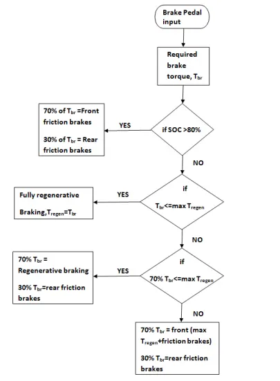
In an electric motor, the Total Brake distribution is in two aspects which are the Electrical Brake which is called Regenerative Brake, and Mechanical Brake or Classical Brake with a hydraulic cylindrical system. Brake Force distribution must be uniform, If the Regenerative braking power requirement is more than the charging limit of the battery or more than the regenerative capacity of the machine we must apply Mechanical brakes as well. In a practical case, the combination of these two is applied. So usually it is a combined response of Mechanical brake and Regenerative brake. The reason for how this braking force is combined is that particular phenomena are called Brake Control Strategies.
In the case of Series, we apply Mechanical brakes and Regenerative electric brake one after another. We can apply only one brake strategy at a time either apply Regeneratively or apply Mechanical brake. The Series Brake Control Strategy has a further classification, that is based on whether we want the comfort of driver or Brake behavior compared to energy efficiency. Parallel - In the case of Parallel, we apply both brakes simultaneously. This Particular Parallel braking is going to happen both at a time. Electric Driven Intelligent Brake (EDIB) is a combination of a Hydraulic brake or Mechanical brake along with a Regenerative brake. It is a Parallel braking technique. The Control criteria such that at low speed use regenerative braking higher and at high speed or during the initial braking period we actually combine the both.
inseries more info------------ parallel braking strategy
3.............................
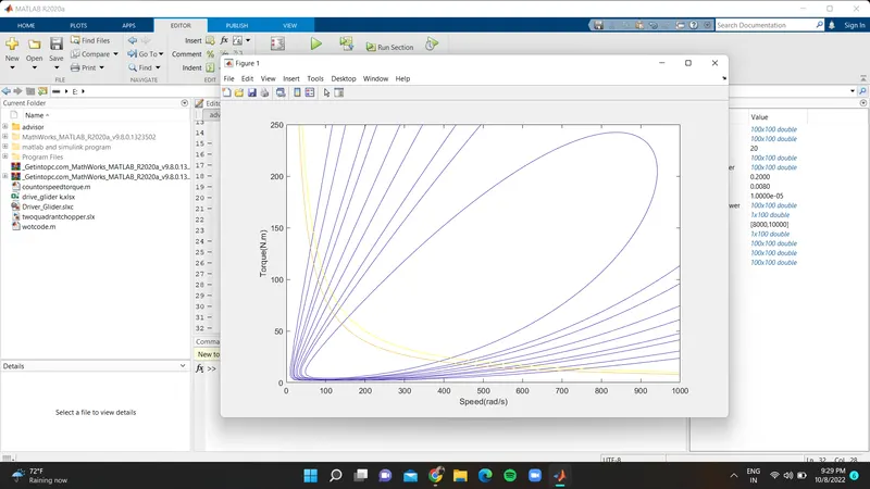
clear all
close all
clc
w = linspace(0,1000);
T = linspace(0,250);
% motor constants
kc = 0.2; % for copper loss
ki = 0.008; % for iron loss
kw = 0.00001; % for windage loss
conL = 20; % for constant motor losses
% making mesh
[X,Y] = meshgrid(w,T);
OutputPower = (X.*Y); % Torque x Speed = Power
B = (Y.^2)*kc; % copper loss
C = (X.^3)*kw; % winding loss
D = X*ki; % Iron loss
InputPower = OutputPower + B + C + D + conL;
Z = OutputPower./InputPower;
% Set the efficiencies for which the contours will be plottted
V = [0.70 , 0.75 , 0.80 , 0.82 , 0.85 , 0.87 , 0.89 , 0.90 , 0.92];
box off
grid off
contour(X,Y,Z,V);
xlabel('Speed(rad/s)')
ylabel('Torque(N.m)')
hold on
V = [8000,10000];
contour(X,Y,OutputPower,V);
Copper Losses - (I^2)R , where R is the Armature resistance and we say that Torque is proportional to Current, this copper loss can be considered as .where is to take care of resistance of brushes and also take care of flux and its effect.
Iron Losses - Iron Losses are nothing but Magnetic losses, which is denoted as , where the factor is based on the Magnetic eld effect. Permanent Magnets have constant Magnetic eld and these Iron losses is based on the value of and this is going to change according to the Speed. At Various Speed have a different values of Back EMF and that is going to affect the Iron Losses.
Windage Losses - This is a Mechanical or friction of Windage losses. This is based on size of shape of Motor and the amount of windage losses that the motor is going to experience.