Week-11 Challenge: Braking
Q .1) For a defined driving cycle , calculate the energy required for braking ?
Calculating the energy required for braking of UDS Drive cycle -
Braking : Braking is a condition to slow down or stops a moving vehicles as required , there are several techniques to apply
Brakes , which can be mechanical or electrical . The most commonly used in techniques is by applying friction . it consume
Energy can be derived as following equation :
Braking Energy = (1/2)*m*v^2
Where , Braking is the kinetic energy in unit of joule .
m = Total mass of the vehicle (vehicle mass + payload) in unit Kg .
V = (Intial Velocity - Final Velocity) in unit m/s
For example if initial speed of a vehicle is 20m/s and final speed is 10m/s . the mass of the vehicle is 500Kg .Then the
Required Kinetic Energy for braking is (1/2)*500*(20-10)^2 = 25000J = 25KJ .
Here for a Drive cycle the required braking energy is calculated for each second of time to slow down or stop the vehicle
Braking energy calculation for UDDS Driving Cycle .
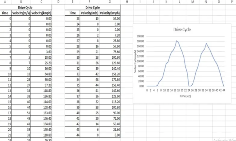
At first time driving cycle the drive cycle is determind in a table and a plot made , using the plot the values from
The braking regions from the vehicle are taken . The plot of the drive cycle is given above . values of the load to
The points of level of the torque values of load.
Q.2) Why electric motor can't develope braking torque at high speed similar to starting ? How electric and
Mechanical brakes are coordinated .
Ans : This situation occurs only when the vehicle is at high speeds because the motor will be running at the constant
Power region . in the constant power region , The torque of the motor reduces and so the motor cannot develope the
Braking torque which is equal to the torque that occured during low speed at the constant torque range .
The torque Vs speed plot a vector control induction motor is given below .
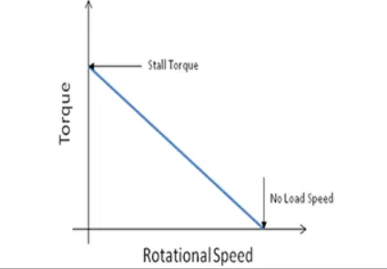
DC Motor Torque Vs Speed characteristics :
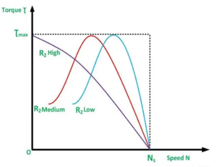
or,The Torque Vs speed plot of a vector control induction motor is given below :
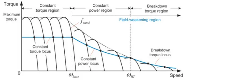
Here for both the cases of AC or DC there is no torque at maximum speed , gradually the torque decreases at high speed
As the speed tends to maximum speed . this situation does not occurs at the begining of acceleration because of most
of the torque is used in increases the kinetic energy of the load (and motor) . But when the speed is already high and no
Extra load is applied it is not possible to increase the torque , the braking operation happens in the motion which is been
Distributed as per proportion in the brake energy and the regenerative braking .
There are two types of braking :
Mechanical Braking : Mechanical brakes all act by generating frictional forces as two surface rub against each other .
The stopping power or capacity of a brake depends largely on the surface area of the frictional surfaces as well as on the
Actuation force applied . Mechanical brakes are assembles consisting of mechanical elements for the solwing or stopping
Of shafts in equipment drives , They use levers or linkages to transmit force from one point to another ,braking slows or
Stop the movement of the coupled shafts , there are several types of mechanical brakes .
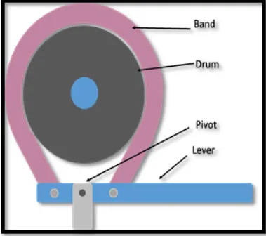
Band brakes : These are the simplest brake configration , have a metal band lined with heat and wear resistant friction
Material .
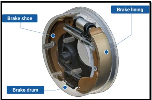
Drum Brakes : These are commonly used in automoblies rear wheels , work shoes press against a spining surface .
called drum :
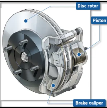
Disc brakes : These are constructed of break pads , a calliper , and rotor . During operation , the brakes pads are squeezed
against the rotor .
Electrical Braking : Electrical brakes are devices that use an electrical current or magnetic actuating force to slow or stop
The motion of a rotating component , they are used in industral and vehicular braking application that required fast response
Times and precise tension control .the magnet in the backing plate has 2 conducter wire which tap directly into the wiring
When electricity is on . it magnetizes the brake magnet . the magnet is attracted to the drum face. when it contracts this
Area , the friction causes it to rotate , which moves the actutating arm and pushes the shoes out against the drum .
Those shoes have have a special brakes pad material on them at that resist the heat caused by that friction . when the shoes
Press against the inside of the drum , they prevent the hub , and consequently the wheel that's touching the ground .
A very beautiful electric braking scheme called regenerative braking is now being employed for electric braking , Here the
During the braking action , the motor is operated as generator . As we know that during generating action , a counter
Torque opposes the motion of motor and motor comes to halt. Moreever , the brake energy is converted to electrical
Which can be fed back to the source using power converters .
- Electric and Mechanical brake Coordination :
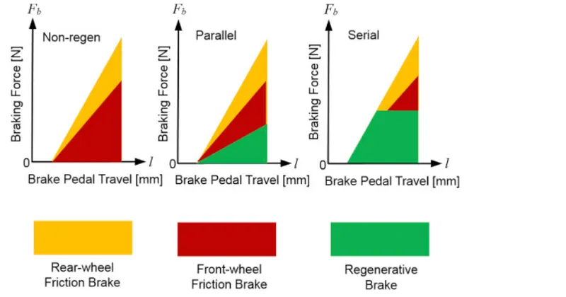
There are mainly 2 ways by which the electric Vehicles could be braked :
- Series - Regenerative braking and mechanical braking both are applied one after another .
- Parallel - Regenerative braking and mechanical braking both are applied one after month .
When brake pedal is pressed the hydraulic fluid reaches the brake piston and created the braking pressure on the wheels
And the same kinetic energy is been used the kinetic energy is been used by the Regenerative braking for generating
More power using the bio - directional motor which operates as a generator while brakings .
Q.3) Make a MATLAB program which plots contour of given motor speed ,torque and efficiency values . Attach
The code as a.m file attach a screenshot of all the plots
MATLAB CODE :
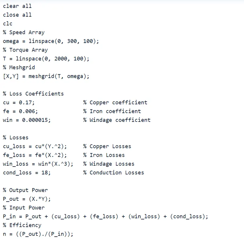
Explanation :
In this MATLAB script , we create arrays for the speed of and the torque of the motor using the 'linspace' command
For the speed , consider a range of values from 0 to 2000 radians per second whereas for the torque ,consider a range of
Values from 0 to 300Nm . These arrays are then used to create 2D grid coordinates will help in the direction and creation of
The contour plot . In order to find the efficiency of the motor , we need to consider the various losses that occurs in the
Motor's operation , these are .
Copper losses
Iron losses
Windage losses
Conduction losses
These various losses are dependent on the speed and the torque of the motor . They each also have a characteristics of the
Constant of the proportinality which are all assumed for the following calculation , the speed and the torque are represent
as 'K' in each calculation , the speed and the torque are represented respectively as : Ns and T .
Copper losses = KCu.Ns2
Iron losses = KFe.T2
Windage losses = Kw.T3
The values of coeffiecint are taken as general values , conduction losses are assumed to be 18 joules .
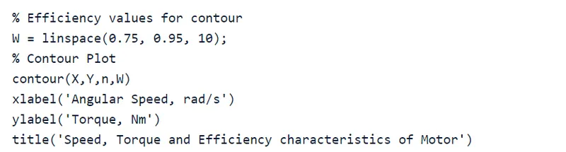
Finally we plot the contour with the help of 'contour' command in addition , an arrays for the effieciency values we want
To plot for is created called 'W' and is aasigned for values ranging from an efficiency level of 0.75 to 095 . This array is used
In the creation of the contour .
Output :
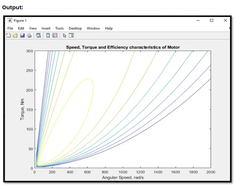
From , this contour plot , we can see that the highest level of efficiency arises in the innermost contour plot and this
efficiency decreases as the contour increasesin size from the innermost contour.