Week - 4
AIM:-
Make a simulate the process of washing machine with given condition.
OBJECTIVE:-
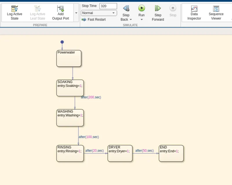
Implement control logic of a ''Washing machine'' using ''Stateflow''as per given
Sequence:
- If the power supply is available, the system gets activated.
- If the water supply is not available stop the process and indicate the LED.
- Soaking time should 200s followed by washing machine time of 100s.
- Then rinsing happen for next 20s & dryer runs for 50s.
- After all the processes have completed turn on the finished LED.
CHART DIAGRAM:-
PARAMETER:
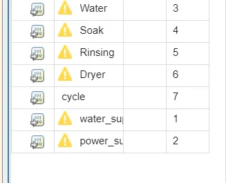
we have a given water,soak,waching,rising,dryer,cycle as output of the chart.
we have given water_supply & power_supply as input of the chart.
OUTPUT:-
There are two condition asked to solve in the equation.
CONDITION:-1
When water supply is OFF.
We should not provide water supply and check for output
Implementing control logic of a "washing machine" using state flow
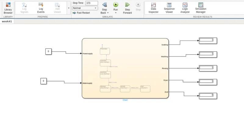
from the above diagram,we can see that indiactor of Water is showing Red i.e; when there is no water
supply the process is terminated and LED TERMINATED is used to indicate that state .
CONDITION:-2
When the water supplyis ON
Now we are providing the water supply and check the output ,
Implementing control logic of a "washing machine" using state flow
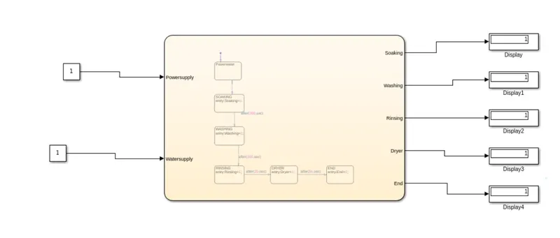
As we can observ from the above figure,all states have been executed and indicating the process completion
indicator (named as cycle) showing GREEN.
CONCLUSION:-
- The simulation of the washing machine using state flow is done and the result is satisfactory
TASK:2
AIM:-
To make a simulink chart for the ''Gear shift''logic.
OBJECTIVE:-
Making a simulink chart for the Gear shift for below mentioned
Speed Range (kmph) Gear
0 to 15 1
16 to 25 2
26 to 40 3
41 to 60 4
Above 61 5
CHART DIAGRAM:-
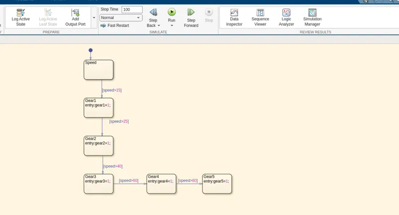
- Here we give speed as input for the chart.
- Here we give speed as output for the chart.
SIMULATION PARAMETER"-
Here we gave time as 'inf'for our simulation should run until we stop it.
OUTPUT:
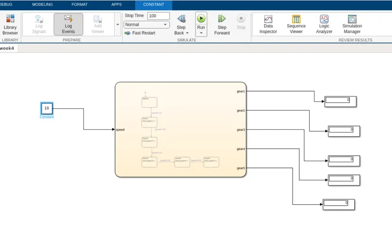
The output produced is recorded when it's displayingthe each gear.
Gear:1-
Speed range :-0 to 15kmph.
Input speed :-10kmph.
Status- All display should be zero
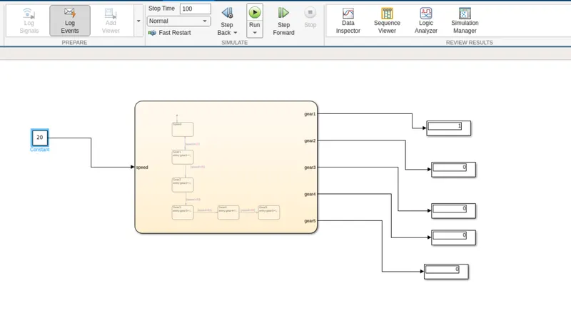
Gear:2:-
Speed range:-16 to 25 kmph
Input speed: 20 kmph
Status-Gear1 ON
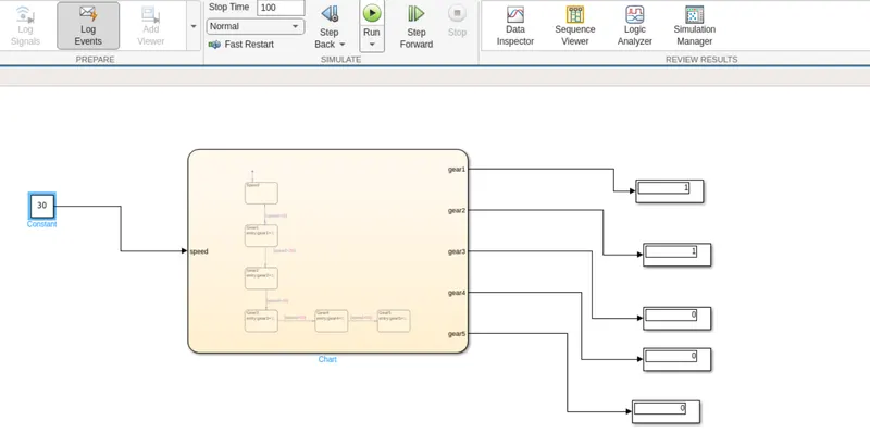
Gear:-3
Speed range:26 to 40 kmph.
Input speed-30 kmph
Status-Gear1 and Gear2 is ON
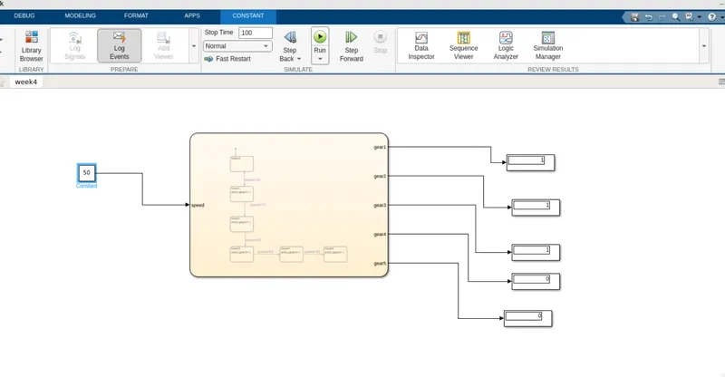
Gear-4:
Speed range:41 to 60 kmph
Input speed- 50 kmph
Status-Gear 1 Gear 2 Gear 3 is ON.
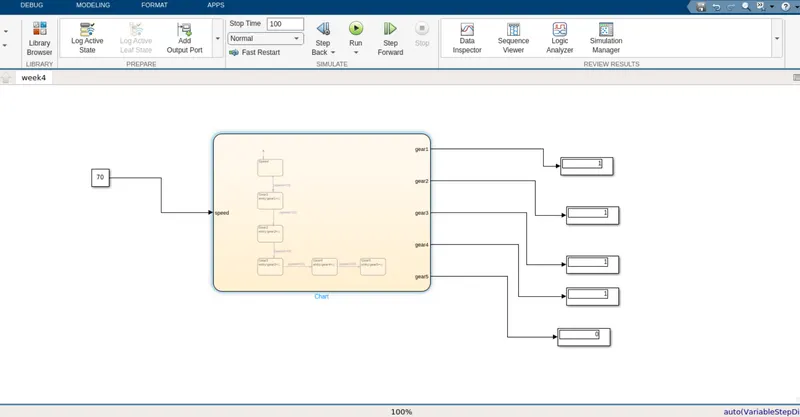
Gear-5:
Speed range:Above 60 kmph.
Input speed:80kmph.
Status-Gear 1 Gear 2 Gera 3 Gear 4 is ON.
CONCLUSION:-
- Created a state flow for gear shift using simulink and the resultare satisfactory.