Week-11 Challenge: Braking
TASK-1
ENERGY REQUIRED FOR BRAKING
DESCRIPTION:
So, for braking power requirement calculation. We have to identify deceleration condition.
Fundamental formula for acceleration and deceleration is
Energy= (1/2) *MV^2.
Let Mass=1000kg
Here we are calculating the deceleration energy or Braking energy.
So, V=Vi-Vf
For example, if the vehicle is decelerated from 25m/s to 15 m/s. The braking energy required is
V=25-15=10m/s
Energy= (1/2) *1000*(10)^2
=50,000 J
The total amount of braking energy required for a simple drive cycle shown below
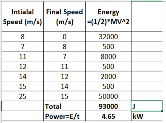
From the above excel calculation sheet Total calculated energy required for braking is 93000 J.
So, from this we find total power required for 20sec is
P=E/t
P= 93000/ (20*1000)
P=4.65 kW
So, Power required for a vehicle become 0speed from 25m/s in 20sec is 4.65kW
For 10sec:
P= 93000/ (10*1000)
P=9.3 kW
For 10sec power required for Braking is 9.3kW which is double than the power required for braking in 20sec which is 4.65kW.
TASK-2
BRAKING TORQUE AT HIGH SPEEDS
- Q) Why Electric motor can’t develop braking torque at high speed similar to starting? How electrical and mechanical brakes are coordinated?
DESCRIPTION:
That’s due to what is called back EMF. The motor starts generating a voltage in reverse which acts against the supply voltage. Thus, the current flow is reduced which, in turn, reduces the strength of the magnetic field which provides the turning torque.
It’s an inherent feature of any wound motor.
I should add that’s the model for a simple electric motor. The sort found in EVs has very complex power controllers which will do things like limit current to avoid burning out motors. For instance, the current at low RPM is likely to be limited to avoid burning out the coils. Up to a certain RPM the controller might be able to maintain the current level and thus torque. However, at a certain point the back EMF will be too high to be fully compensated for and then torque will start to fall away with higher RPM.
Hence a simple chart of maximum power and torque vs RPM might look like this: -
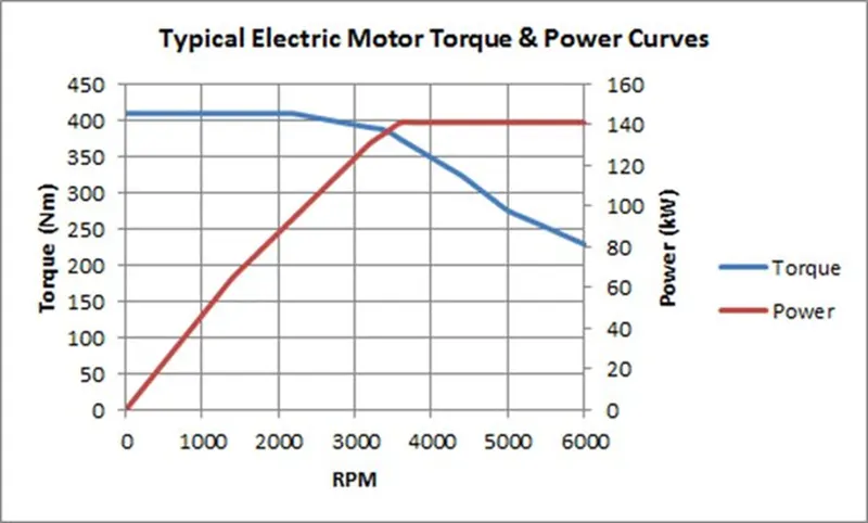
In practice, power will start to drop off too as that back EMF effect becomes more significant. There are ways round this by using a gearbox, but one of the advantages of EVs is avoiding the need for such a device in the power train.
In DC motor operation (separately excited field type), the speed is proportional to the inverse of field magnetic flux but torque is proportional to the flux. The motor speed is controlled by varying the field voltage. Decrease the field volts (thereby flux) to increase the speed but it reduces the torque.
AC motor speed control is done in a different way. The most commonly used motor is AC induction motor. In variable speed applications, inverter is used to control the speed of the motor by varying the frequency applied to the motor. The speed is proportional to the frequency. Until the base speed (nominal speed) the voltage to frequency ratio is kept constant which in turn keeps the air gap magnetic flux constant. The torque is proportional to the flux hence remains constant until the base speed. As power is the product of speed & torque, the power keeps increasing with speed until the base speed. This is called the constant torque mode of operation.
Beyond base speed, the speed is increased by increasing the frequency alone keeping voltage constant. In this mode, the air gap flux decreases with increasing speed. The product of speed & torque remains constant in this operation beyond base speed. This is constant power operation.
Electrical and Mechanical Brakes Coordination:
Braking systems are necessary for the correct and safe operation of mechatronic systems. Most functional braking is achieved using electrical braking, which is made possible by the addition of a variable speed drive system (e.g., variable frequency drive system). Electrical braking is efficient and ensures smooth operation and allows the designer to recover the mechanical energy. However electrical braking cannot be used as a safety braking system for the cases of emergency braking and parking braking. It is for these reasons that mechanical braking systems are still employed today, in order to act as emergency and parking brakes.
The Rationale for Braking Systems
In any motion control system, braking is necessary for the following reasons:
- In order to stop the system in cases of emergency.
- In order to ensure that the system follows the correct speed time profile.
- In order to ensure that the system remains stationary when not in operation.
Two types of braking systems are employed in most drive systems: electrical and
mechanical. In this note a general overview is presented of the two types of braking
systems, and it concludes with a comparison of the two types.
Types of Electrical Braking Systems:
There are six methods of electrical braking in drive systems, listed below:
- Plugging: The three-phase voltage sequence is reversed at the stator terminals of the induction motor. The equivalent form of plugging in dc drive systems is the reversal of the polarity of the armature voltage of a dc motor.
- DC Injection Braking: A d.c. voltage is applied to any two of the three terminals of the induction motor.
- Eddy Current Braking: A separate eddy current braking device is coupled to the shaft of the motor. Eddy current braking results when electromagnets are activated and they induce eddy currents in the rotating metallic disk. The eddy currents produce magnetic fluxes that oppose the flux produced by the electromagnets and thus result in a braking torque on the motor. The energy is dissipated as heat in the rotating metallic disk.
The next three methods are used in variable frequency drive systems and aim to remove the excessive charge on the dc link capacitor in the variable frequency drive system.
- Dynamic Resistor Braking: In variable frequency drive systems, when the motor is braking and acting as an induction generator, it returns power back to the d.c. link capacitor and the voltage of the d.c. link increases. A resistor can thus be used to dissipate the excessive charge on the capacitor, whereby an IGBT is controlled to proportionately switch the resistor in parallel with the capacitor (using pulse width modulation switching). The excessive energy is thus dissipated in the resistor.
- Regenerative Braking: Rather than dissipating the excessive charge in the resistor, it is possible to return the excessive energy back to the three-phase supply by using a dedicated inverter, placed in parallel with the uncontrolled rectifier that is used in the variable frequency drive system.
- Sharing the DC Bus: Another possible method of removing the excessive charge on the capacitor is to share the d.c. between a number of different variable frequency drive systems. The drive that is braking can supply energy to the drive that is motoring. In such a case, there is no need to dissipate the excessive energy into a resistor or to return it to the three-phase power source.
In the first two methods, the excessive energy is dissipated as heat in the motor
itself. In the Eddy current method, the excessive energy is dissipated as heat in the
metallic disk. In the fourth method, the excessive energy is dissipated as heat in the
resistor. In the fifth method the energy is returned to the ac suppy. In the sixth
method, the energy circulates between the different motors (from the one that is
acting as a generator to the one that is acting as a motor).
In cases where it is possible to recover the energy, the following can be done:
- It can be stored in batteries.
- It can be stored in a flywheel (a flywheel that has an integrated permanent
magnet dc alternator).
- It can be returned to the ac supply using a regenerative drive.
Mechanical Braking Systems:
There are four types of mechanical brakes used in drive systems:
- Drum brakes.
- Disk brakes.
- Band brakes.
- Pawl and Ratchet brakes: The ratchet is linked to a spring-loaded friction plate. The ratchet is lifted using a solenoid.
The drum and disk brakes are either electromagnetically lifted or hydraulically lifted,
but always spring applied. They must be spring applied for safety reasons, so that
when the power supply is lost, the brake will apply and safely bring the load to a standstill.
Comparison between Electrical and Mechanical Braking Systems:
The following is a comparison between electrical and mechanical braking systems:
- Electrical braking systems are used for functional braking (controlling the
speed; bringing the load to standstill). Mechanical braking systems are used
for emergency stopping or for parking.
- Electrical braking is usually very smooth and comfortable. Mechanical braking
is usually rough and uncomfortable.
- No wear results from electrical braking. Mechanical braking on the other hand
causes wear in the braking components and requires regular maintenance.
- It is possible (but not always feasible) in electrical braking systems to return
the regenerated energy back to main supply. This is not possible in mechanical braking systems and the energy is always lost as heat, noise and wear.
- The electrical braking system cannot be used as a safety device. Most
systems will require a mechanical braking system as a backup safety device.
Regenerating braking not alone used to stop the vehicle in Emergency condition. Both mechanical and electrical braking will use combinedly.
For low-speed braking regenerating braking is used higher percentage and for high-speed braking both mechanical and electrical used together.
If we apply the brake by using braking pedal the control signal is send to both hydraulic brake & Regenerative braking and From regenerative braking control signal is given to Power converter.
TASK-3
CONTOUR OF MOTOR SPEED, TORQUE AND EFFICIENCY
DESCRIPTION:
To plot the contour line for a given motor. A motor has various types of losses occur inside.
Types of losses are:
Copper losses- I2*R Where R is the armature resistance and we know that torque is proportional to current, then copper losses are proportional to square of the Torque.
Copper losses = Kc*T^2
Iron losses: Iron losses are nothing but Magnetic losses. These are varying with speed due to magnetic field is changes with the speed
Iron losses= Ki*w
Windage losses: These are mechanical losses due to friction and windage losses. These are dependent on size and shape of the motor.
Windage losses = Kw*w2
Constant losses: denoted as C
Total Losses= Kc*T^2 + Ki*w + Kw*w2 +C
MATLAB SCRIPT:
% The x axis corresponds to motor speed (w)
% and the y axis ti torque T
% First set up arrays for range
X = linspace (1,1000); %speed, N.B. rad/s
Y = linspace (1,1250); % 0 to 40 N-m
% allocate motor loss constants
Kc=0.2; % For copper losses
Ki=0.008; %For iron losses
Kw=0.0001; %For constant motor losses
ConL=20; %For constant motor losses
%Now make mesh
[X,Y]=meshgrid(X,Y);
outputpower= (X.*Y); %Torque X speed=power
B=(Y.^2)*Kc; %cu losses
C=X.*Ki; %Iron losses
D=(X.^3)*Kw; % WIndage lossses
Inputpower=outputpower+B+C+D+ConL;
Z=outputpower./Inputpower;
% We now set the efficiencies for which a contour
% will be plotted
V=[0.70,0.80,0.85,0.90,0.91,0.92,0.925,0.93];
box off
grid off
contour (X,Y,Z,V);
xlabel('speed/rad.S^-^1'), ylabel('Torque/N-m');
hold on
% New plot a contour of the power o/p
% The array output power has
% already been calculated. We draw contours at
% 3 and 5 Kw
V=[8000,10000];
contour(X,Y,outputpower,V);
RESULTS:
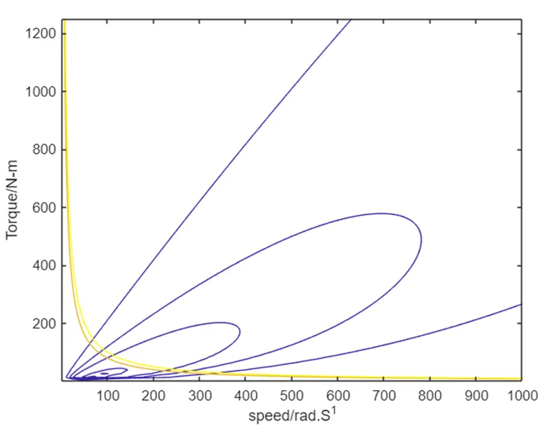
The above plot shows the Motor speed, Torque and efficiency contour plot. Observed highest efficiency of the motor is 93% from above results.