Week-11 Challenge: Braking
Question1: For a defined driving cycle, calculate the energy required for braking.
CASE1:
considering the velocity of a vehicle from 63 sec to 74 sec
kerb weight = 800kg
payload = 400kg
total weight (m) = 1200kg
initial velocity(V_i) = 80kmph = 22.22m/sec
final velocity(V_f) = 0 kmph
time taken to decelerate the vehicle = 11sec
1.energy required for braking:
E = 1/2.m.(Vi - Vf)
= 1/2*1200*(22.2 - 0) = 13.320kj
2.force required for braking:
F = m.d
where d = (V_i - V_f/t) t = time in sec
F = 1200.(22.2-0/11) = 2.42KN
3.power required for braking:
P = F.(Vi-Vf)
= 2.42(22.2-0) = 53.72kw
CASE2:
considering the velocity of a vehicle from 31sec to 41 sec
kerb weight = 800kg
payload = 400kg
total weight (m) = 1200kg
initial velocity(V_i) = 59kmph = 16.38m/sec
final velocity(V_f) = 30 kmph = 8.3m/sec
time taken to decelerate the vehicle = 10sec
1.energy required for braking:
E = 1/2.m.(Vi - Vf)
= 1/2*1200*(16.38 - 8.3) = 4.848kj
2.force required for braking:
F = m.d
where d = (V_i - V_f/t) t = time in sec
F = 1200.(16.38-8.3/10) = 0.881KN
3.power required for braking:
P = F.(Vi-Vf)
= 0.881(16.38-8.3) = 6.130kw
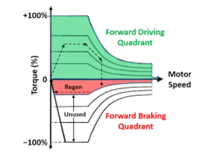
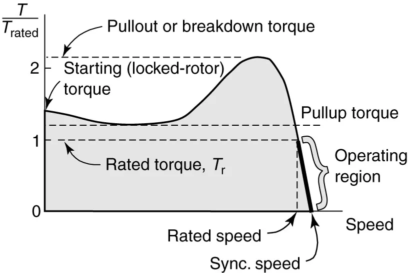
Question2:Why electric motor can’t develop braking torque at high speed similar to starting?
A running motor may be brought to rest quickly by either mechanical braking or electrical braking. The mechanical braking is applied by means of mechanical break shoes. Hence the smoothness of mechanical braking is dependent on the surface and physical condition of brakes. Smooth braking of a motor can be achieved by electric braking.
Electric Braking
(ii) Plugging or Reverse current braking:
In this method, armature connections are reversed and hence motor tends to run in opposite direction. Due to reversal of the armature terminals, applied voltage V and back emf Eb starts acting in the same direction and hence the total armature current exceeds. To limit this armature current a variable resistor is connected across the armature. This is similar for both series and shunt wound methods.
Plugging gives greater braking torque as compared to rheostatic braking. This method is generally used in controlling elevators, machine tools, printing presses etc.
(iii) Regenerative braking:
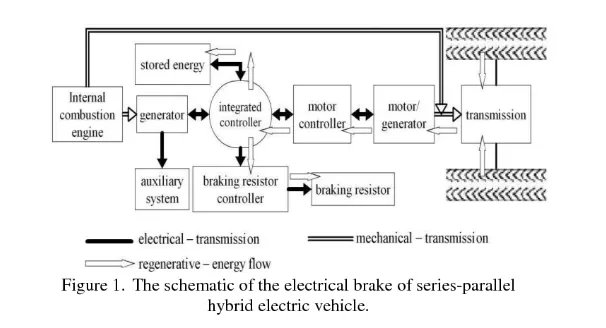
Regenerative braking is used where, load on the motor has very high inertia (e.g in electric trains). When applied voltage to the motor is reduced to less than back emf Eb, obviously armature current Ia will get reversed, and hence armature torque is reversed. Thus speed falls. As generated emf is greater than applied voltage (machine is acting as a DC generator), power will be returned to the line, this action is called as regeneration. Speed keeps falling, back emf Eb also falls until it becomes lower than applied voltage and direction of armature current again becomes opposite to Eb.
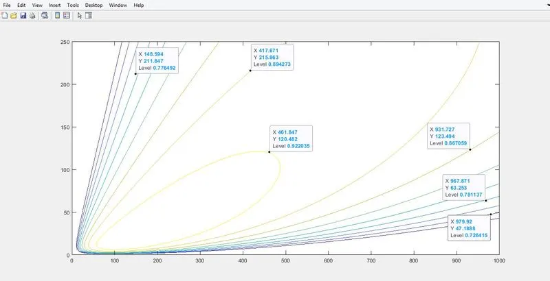
clear all
close all
clc

%inputs
%speed array(W)
W = linspace(0,1000,250);
%torque array(T)
T = linspace(0,250,250);

%loss coefficients
%copper losses(Kc)
Kc = 0.20;
%iron losses
Ki = 0.008;
%windage losses(Kw)
Kw = 0.000018;

%meshgrid
[X,Y] = meshgrid(W,T);
copper_loss = (Y.^2)*Kc;
iron_loss = X.*Ki;
windage_loss = (X.^3)*Kw;
c = 25;

%output power(P_o)
P_o = X.*Y;
%input  power(P_in)
P_in = P_o + (copper_loss + iron_loss + windage_loss + c);

%Efficiency(E)
E = (P_o./P_in);
n = linspace(0.7,0.95,10);
contour(X,Y,E,n)
Xlim(0,1000)
Ylim(0,250)
xlabel('speed(rad/sec)')
ylabel('torque(N_m)')