Week-11 Challenge: Braking
Q1. For a defined driving cycle, calculate the energy required for braking.
Soln:
Driving cycle is a series of data points representing the speed of vehicle versus time. It has acceleration and deacceleration points means where velocity increases and decreases with respect to time. For deaccelerations points breaking is responsible, for these points we can calculate breaking energy as well.
As we require to stop vehicle in stipulated time, we cannot allow vehicle to stop as per its inertia value, for stopping vehicle we require to apply brake. Braking of vehicle is required to deaccelerate vehicle to lower speed within a given time.
Breaking energy is the kinetic energy which must be removed from moving object, to stop it generally breaking energy is given by the following formula.
Ebr = 0.5*m*V²
Ebr = 0.5*m*(Vf - Vi)²
where,
Ebr = Braking energy
m = Mass of vehicle
V = Velocity difference(V_final - V_initial)
Vf = Final Velocity
Vi = Initial Velocity
We have defined a drive cycle for 90seconds.
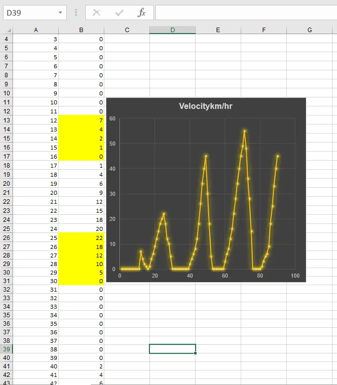

We take the total weight of the vehicle as 800kgs
We have 4 cases in the drive cycle where the vehicle brakes.
We calculate V in m/s by multiplying it by 5/18.
First instance, Velocity = 7 to 0 kmph
V = 7 - 0 = 7 in 5 sec = 0.388
Ebr1 = 0.5* (800* 0.388)/1000 = 0.0605
Second instance, Velocity = 22 to 0 kmph
V = 22 - 0 = 22 in 6 sec = 1.019
Ebr2 = 0.5* (800* 1.019)/1000 = 0.415
Third instance, Velocity = 45 to 5 kmph
V = 45 - 5 = 40 in 4 sec = 2.778
Ebr3 = 0.5* (800* 2.778)/1000 = 3.087
Fourth instance, Velocity = 55 to 0 kmph
V = 55 - 0 = 55 in 6 sec = 2.55
Ebr4 = 0.5* (800* 2.55)/1000 = 2.56
Total Brake power = Sum of all Brake powers
Ebr = 0.0605 + 0.415 + 3.087 + 2.56
Ebr = 6.1225
Hence , The energy required for braking is 6.1225 kWh.
Q2. Why electric motor can’t develop braking torque at high speed similar to starting? How electric and mechanical brakes are coordinated?
Soln:
At high speed the torque will be less and operates at constant power region hence it is difficult to bring the vehicle to rest or deaccelerate immediately. The peak acceleration torque is greater than the peak deacceleration torque. Hence braking torque of EV motor is not as high as acceleration torque.
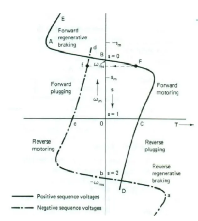
The speed torque curves obtained by the reversal of the phase sequence of the motor terminal voltages are also shown by the dotted lines.
With a positive sequence voltage across the motor terminals, the operations above synchronous speed gives the regenerative braking operation (portion BAE).
Similarly, with a negative sequence voltage across the motor terminals, regenerative braking is obtained for speeds above the synchronous speed in the reverse direction(portion bae). In regenerate your braking, the motor works as induction generator converting mechanical energy supplied to the load electrical energy which is fed to the source. Thus the generated energy is usefully employed.
Speed and Torque Characteristics of a DC motor :
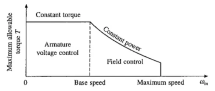
When we press the brake pedal, we cut off power supply to the motor and now the motor will be in the rotation due to its inertia. As this rotation is happening inside the magnetic field a back EMF is generated which produces a negative torque and that used as the breakes to reduce the vehicle speed. Also the current flows in the reverse direction, using a bidirectional inverter we can store the current back into the battery.
During the initial low speed, the torque is high which is the constant torque region. As speed builds up, after the critical speed point the torque gradually decreases which is known as the constant power region. So during high speeds, the motor will be at constant power region and while breaking, due to the high speed of the motor negative torque produced will be less.
But while starting the motor, the speed will be very less and at this stage the motor will be operating in a constant torque region and most of the torque is used to increase the kinetic energy of the load (and motor). But when the speed is already high and no extra load is applied it is not possible to increase the torque.
There are other reasons like battery limitations due to which we cannot get high breaking torque also the rate of discharge is always higher than the rate of charging due to the battery's chemical composition.
Electric and mechanical brakes are coordinated :
we can classify the breaking into two parts:
1. Mechanical Braking :
Mechanical Braking mostly used in scooters, motor vehicles and motorcycles where a small power is required. It is essential in manufacturing power transmission applications, material handling etc. It delivers forces to the axle or a wheel in order to stop motion. It helps to reduce the speed of the system slowly by the mechanical processes when compared to the electrical braking. The working of mechanical brake depends on the pedal, when the pedal is pressed the brake shoes or pushed outwards and rotates against the drum which is connected to the wheels. Hence the machine or vehicle gets slow down and stopped. And when the pedal is released, it goes to normal position due to the pullback action of spring shoes.
- Drum braking
- Disk braking
- band braking
- Pawl and Ratchet braking
2. Electrical Braking - Electrical braking is used to reduce the speed of the machine depending on flux and torque. This type of braking is mainly usedd for functional braking to control the speed of the machine. It is easy to handle and comfortable, but it cannot be used for emergency braking and parking braking.
- Plugging type braking
- Dc injection type braking
- Eddy current braking
- Dynamic resistor type braking
- Regenerative braking
- Sharing DC bus type braking
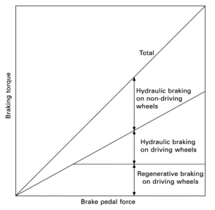
The braking stability of electric vehicles with electro-hydraulic hybrid braking systems can be influenced by braking force distribution between hydraulic braking force and regenerative braking force.
Electric cars regenerative braking and this does substantially reduces they need for hydraulic braking. But there are some limitations like maximum deacceleration with the engine alone is far smaller than with brake assistance so you still need an ordinary fractional braking system to make car stop instantly if required. When the regenerative capacity is less than the actual breaking required, mechanical brakes are applied to those at those times.
During low brake pedal force, only regenerative braking torque is applied on the driving wheels and is proportional to the pedal pressing force. The braking torque on the non-driving wheels is always due to hydraulic braking which is also proportional to the pedal pressing force.
When the pedal force is beyond a certain limit, the maximum regenerative braking torque is applied on the driving wheels, and the hydraulic braking torque is simultaneously applied on the driving wheels to top up the desired braking torque. Meanwhile the maximum regenerative braking torque is kept constant to fully recover the kinetic energy.
There are 2 ways of applying the combination of brakes and they are classified as :
- Serial Braking - regenerative breaking and frictional breaking are applied one after another.
Serial regenerative breaking is basically based on the combination of friction-based adjustable braking system that transfers energy to the electric motors and batteries under an integrated control strategy. The overall design of serial regenerative braking is to estimate the deacceleration required and distribute the required braking force between the regenerative braking system and the mechanical braking system. The serial braking system requires brake by wire system and has a more consistent pedal feel due to good torque blending capability. It can increase the efficiency by 15-30%.
Implementation of serial braking strategy :
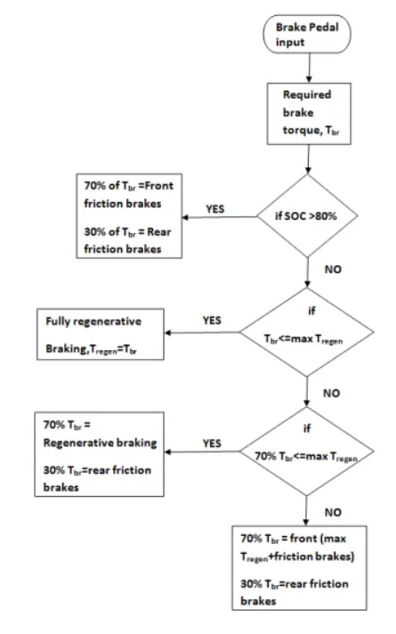
Once a break pedal is pressed and depending on the level of depression, a brake torque he sent. Now this brake torque passes into the brake control strategy block. Here, firstly it is checked if battery state-of-charge is below 80% which is set as maximum permissible level of charge. If that condition is satisfied, then the batteries recharged.
The brake torque requested is compared to the maximum regenerative torque limit of the motor generator. If the overall brake torque requested is less than or equal to the maximum regenerated torque, then the vehicle brakes purely on regenerative torque and the battery is charged. The amount of charge ultimately put in depends also on the motor-generator operation efficiency and then the battery charging efficiency. If the overall brake torque requested is greater than whaat the motor-generator can provide then the friction brakes kicks-in.
Now since the vehicle is front driven it is checked if the total brake torque requested from front is less than or equal to maximum regenerative torque capability of motor generator. If yes, than the front breaking is provided purely by regeneration and rare (non driven axle) by friction. Once the total brake torque request increases further, then front friction (driven axle) comes into play in combination with rear friction brakes and front regenerative braking, to satisfy the overall brake torque demand. This has been represented in a flowchart manner shown below :
2. Parallel Braking - Regenerative braking and frictional braking are applied at the same time. A parallel braking system is basically based on the combination of a friction-based system and the regenerative braking system operated in tandem without an integrated control. The regenerative braking force is calculated from the brake control unit comparing the requested brake torque and the motor torque available. A parallel regenerative braking system requires more work in achieving good torque blending. This system can increase the efficiency by 9-18%.
Implementation of parallel braking strategy :
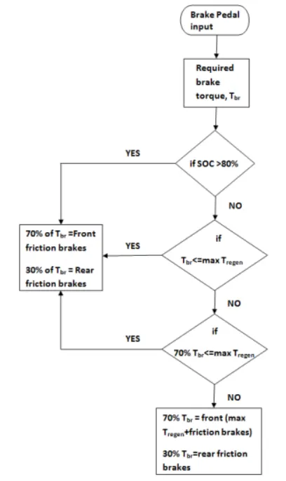
Once the break pedal is applied and a desired overall brake torque request is sent from the driver block. This brake torque on passing through the brake control strategy gets divided between regeneration and friction breaking at all times. The strategy is so modelled with the comfort and brake pedal feel in mind. As a parallel regenerative braking is an add-on to the conventional systems, it is devoid of any integrated control. So to make the transition and Co-performance of regenerative braking with friction smooth, it is assigned in such a way that, there is a clear division between the amount of brake torque that will be achieved from regeneration and friction braking. On application of brakes and in keeping with the design of motor-generator, it is designed to operate generator in a constant generator torque region. Motor-generator can provide a maximum of 322 Nm of generator torque at or under the base speed. The generator is scaled such that the base speed of the generator corresponds to a velocity of 124[kmph], which is the maximum speed limit on most highways hence generation works, as long as vehicle is breaking from a speed of under 124[kmph] and the requested breaking torque on the front driven wheels, after the front rear-break split is greater than or equal to maximum generator torque. If that condition is satisfied, then regenerative and friction braking operates in tandem else it's just the friction brakes or the driven and non-driven Axle. This has been represented in flowchart manner as shown below :
Q3. Make a MATLAB program which plots contour of given motor speed, torque and efficiency values. Attach the code as a .m file attach a screenshot of all the plots.
Soln
Matlab Code:
% motor characteristics
% speed vs torrque efficiency

clear all
close all
 clc

 w = linspace(0,1000); % speed of the motor
 t = linspace(0,250); %torque

 % motor losses
 % for copper loss
 k_c = 0.2;
 % for iron loss
 k_i = 0.008;
 % for winding loss
 k_w = 0.00001;
 % constant loss
 cl = 20;

 %Making 2d matrix
 [W,T] = meshgrid(w,t);

 % Output power = torque*speed
 Out_power = (T.*W);
 % copper loss
 b = (T.^2)*k_c;
 % Winding loss
 c = (W.^3)*k_w;
 % Iron loss
 d = W*k_i;

 % Input power
 In_power = Out_power + b + c + d + cl;
 %Efficiency
 E = Out_power./In_power;
 %Efficiency  levels for contour
 e = [0.70,0.75,0.80,0.82,0.87,0.89,0.90,0.92];

 %plotting the graph
 % creating contour
 [C,h] = contourf(T,W,E,e);
 clabel(C,h,'labelspacing',300); %plotting the efficiency values and its spacing
 xlabel('Speed');
 ylabel('Torque');
 title('Motor Speed, Torque and Efficiencies')
Explanation :
- The program starts with assigning input of the Speed and Torque in an array using 'linspace' command and allocate constant values for four losses (Copper loss, Iron loss, windage loss and Constant motor loss).
- Mesh the Speed and Torque values using'Meshgrid' command. Basically it makes the size of both array equal.
- Calculate the output power by multiplying Speed and Torque values.
- Calculate Copper loss, Iron loss Windage loss using those formulas.
- Calculate Input power by adding Output power and 4 losses(Copper loss, Iron loss, windage loss and Constant motor loss).
- The ratio of output power and input power we can get the efficiency.
- Now set the efficiencies for which a contour will be plotted. The range of contour efficiency is to plot the contour efficiency using 'contour' command and plot Speed,Torque,Efficiency and V.'contour(X,Y,Z) specifies the X and Y coordinates for the values in Z.Contour(Z) creates a filled contour plot containing the isolines of matrix Z, where Z contains height of values on the x-y plane.
- clablel(C,h) labels the current contour plot with rotated text inserted into each contour line. The contour lines must be long enough to fit the label, otherwise clabel does not insert a label.
- Now the below plot shows the motor speed torque efficiency contour plot with increasing efficiency order as going inward and decreasing efficiency order as going outward.
Output :
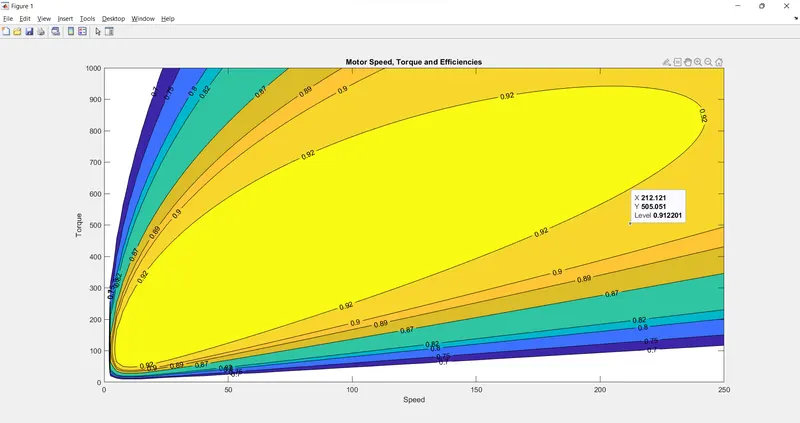
The above figure shows the contour plot and the X-axis is Speed and Y-axis is Torque and the height Z axis is Efficiency.
The color bar is used to know the efficiency based on the color of shading in the plot ranging from 0.75 to 0.93.
The contour plot represents the operational condition of the permanent magnet DC motor.
The efficiency of the motor is High at lower values of Speed and Torque at 0.93. As Speed and Torque increases the efficiency of the motor goes down upto 0.75 value of efficiency.
Thus the contour plot is made using a matlab program for an electric motor with given Speed, Torque and Efficiency values.
Conclusion : Matlab code for program which plots contour of given motor speed, torque and efficiency values is sucessfully built and excuted.