Week-11 Challenge: Braking
(1) For a defined driving cycle, calculate the energy required for braking.
Answer:
DRIVING CYCLE: driving cycle is a series of data points representing the speed of a vehicle versus time. Driving cycles are produced to assess the performance of vehicles in various ways, including fuel consumption and polluted emissions.
Driving cycle uses:
- analyzing battery state and energy consumption in electric vehicle
- performance of vehicle(fuel consumption,emission test)
BRAKING: Braking is most important concept of the vehicle safety.braking is a condition to stop or slow down the vehicle as required.the occuring barking in vehicle in elctrical or mechanical brake applied on the vehicle.in urban area driving significant amount of energy consumed during braking. in elctric vehicle it is possible to recover energy lost during braking.
kinetic energy(Ek): 1/2 mv^2
where m= mass of the vehicle (kg)
v= velocity of vehicle (m/s)
Ek = kinetic energy (J)
calculation of enrgy reuired for the braking for defined drive cycle:
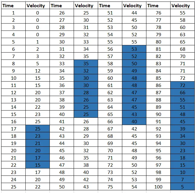
in the above driving cycle 4 different condition of speed decceleration that condition energy has to be calculated.
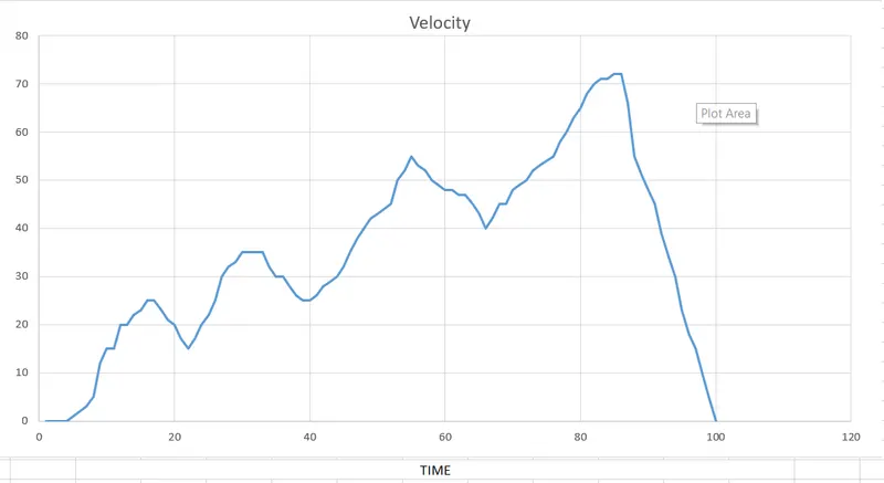
first braking= 25 to 15 km/hr in 6 sec.
second braking= 35 to 25 km/hr in 8 sec.
third braking= 53 to 40 km/hr in 11 sec.
fourth braking = 72 to 5 km/hr in 15 sec.
Drive cycle:
Calculating energy required for braking using excel calculator:
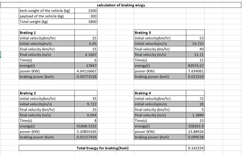
Total braking energy required = 0.142154.
(2) Why electric motor can’t develop braking torque at high speed similar to starting? How electric and mechanical brakes are coordinated?
Electric motor can't develop braking torque at high speed similar to starting, because Braking Torque of an EV Motor is not as high as the Acceleration Torque. Therefore Regenerative braking is cannot happen so effectively that we can get all the power back to the battery. this can be attributed to many reason such as rate of discharged of the battery is higher then charging rate it can be said that the discharged rate can betwise as the rate of charging rate. there are another limitation to the motor in the form of power converter. power converter is customized three phase inverter which are bidirectional as it need to convert regenerative braking energy back to dc current for the battery and this reduces the efficiency of the power converter at low speed regenerative braking is very high as speed increases. the regenerative braking reduces as the effectiveness of inverter play important role and the overall efficiency reduces resulting in reduced braking torque. hence for effective braking high speed, we used a combination of hydraulic brake and regenerative brake.
ELECTRIC AND MECHANICAL BRAKES CO-ORDINATED:
In the electric motor the total brake distribution is two aspect which are mechanical braking and electrical braking(regenerative braking) system. brake force distribution must be uniform, if regenerative braking power requirement is more then the charging limit of the battery or more then regenerative capacity of the machine we must apply mechanical brakes as well. in practically case the combination of these two is applied. so it is combined response of the mechanical brakes and regenerative brakes. that phenomena is called as brake control strategies. this are following
Two type brake control strategies are used to organise the mechanical and electric brake they are:
- parallel control
- series control
- parallel control : When the brakes is applied according to the brake pedal travel the front wheel friction brake, the rear wheel friction brakes and brakes are employed simultaneously. the higher the travel of the brake pedal the higher the amount of braking will be done.
- series control: when the brakes is applied according to the brake pedal travel the front wheel friction brake, the rear wheel friction brakes and the regenerative brakes are applied a one after another. as the braking requirement increases the frictional brakes are used subsequently. for the low speed of the vehicle, regenerative braking is used to but it may be limited according to state of charge of the battery. the speed of the vehicle increases the rear wheel frictional brake will be employed if the braking requirement is not done but then the front wheel frictional brake is also used. the co-ordinates of the series control braking can be done with the choice to the energy storage.
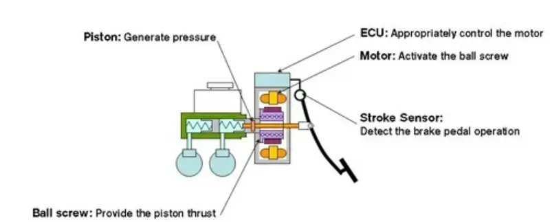
Electric driven intelligent brakes(EDIB):
EDIB is the combination of mechanical brake along with a regenerative brake.it is parallel control technique. the control criteria such that low speed use regenerative braking higher and the high speed during initial braking period we actually combined the both.
(3) Make a MATLAB program which plots contour of given motor speed, torque and efficiency values. Attach the code as a .m file attach a screenshot of all the plots.
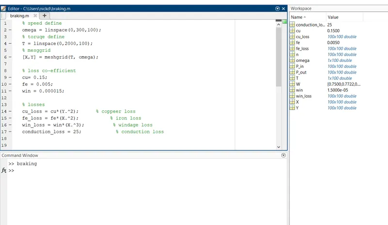
MATLAB CODE:
% speed define
omega = linspace(0,300,100);
% toruqe define
T = linspace(0,2000,100);
% mesggrid
[X,Y] = meshgrid(T, omega);
% loss co-efficient
cu= 0.15;
fe = 0.005;
win = 0.000015;
% losses
cu_loss = cu*(Y.^2); % coppeer loss
fe_loss = fe*(X.^2); % iron loss
win_loss = win*(X.^3); % windage loss
conduction_loss = 25; % conduction loss
% output power calculation
P_out = (X.*Y);
% input power
P_in = P_out +(cu_loss) + (fe_loss) + (win_loss) + (conduction_loss);
% efficiency
n = ((P_out)./(P_in));
% calculation of efficiecy
W= linspace(0.75, 0.95, 10);
%contour plot
contour(X,Y,n,W);
xlabel('angular speed, rad/s');
ylabel('torque, Nm');
title('speed, torque and efficiency charachtertics of motor');
OUTPUT:
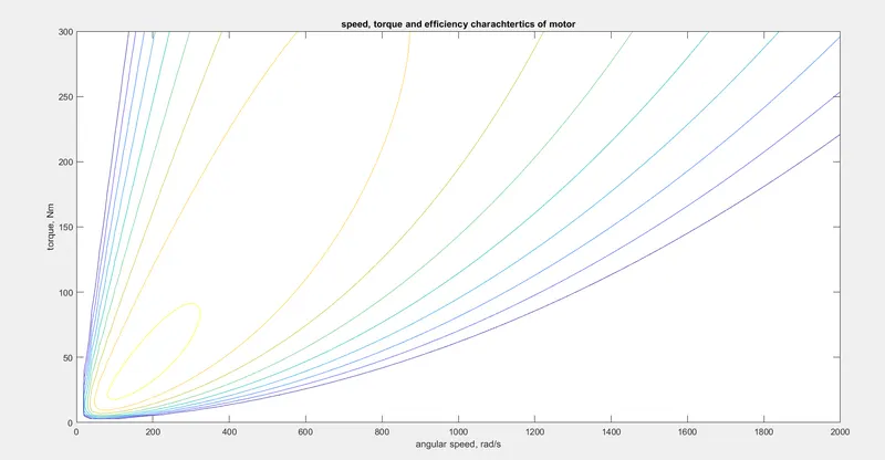
In the above plot defined speed vs torque based on efficiency speed and torque increases the efficiency of motor is gradually decreases.