Week-11 Challenge: Braking
1.Objective:
- To calculate the energy required for braking for a defined drive cycle.
UDDS Drive Cycle:
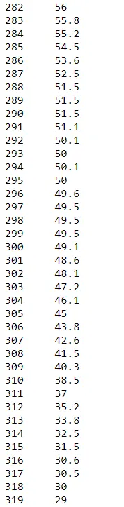
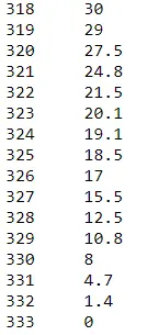
- UDDS stands for Urban Dynamometer Driving Schedule, and refers to a USEPA mandated dynamometer test on fuel economy that represents city driving conditions which is used for light duty vehicle testing
- The drive cycle is defined for 1369 seconds and it will cover a distance of 7.45miles.
- The top speed is aroumd 58 mph,which is about 25.9m/s.
Brake Energy Calculation:
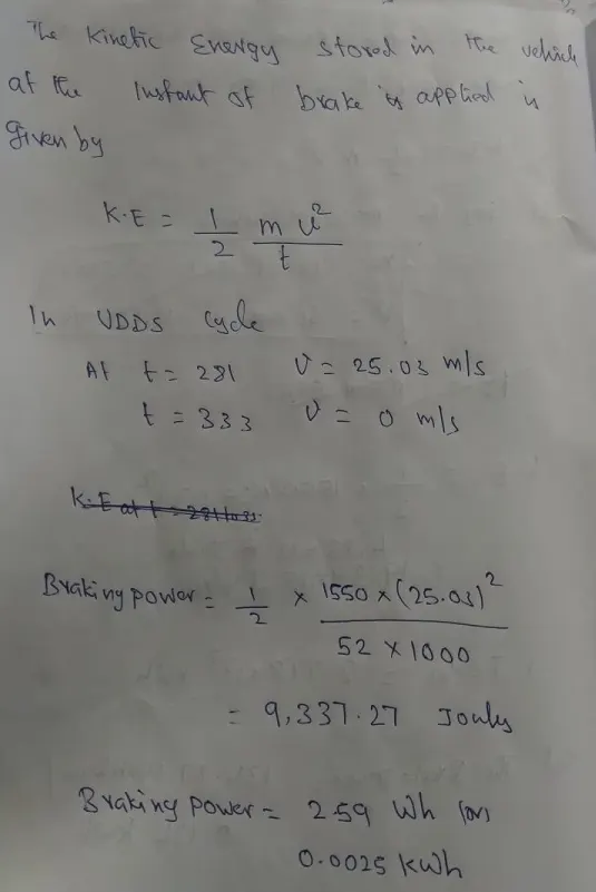
- The Kinetic energy stored in the vehicle at the instant of brake applied will be calculated
There is one correction in the Excel calculator for the calculation of braking power
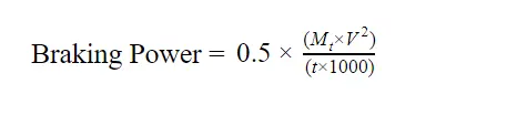
Mt = Total weight of vehicle
V = Vehicle speed in m/s
t = Deceleration time
clc
clear all;

timePeriod = 1370
num = xlsread('Bookudds.xlsx');
time = num(1:timePeriod,1);
velocity = num(1:timePeriod,2);

instantBrakeEnergy = zeros(1,length(velocity));
totalBrakeEnergy = 0;

mass = 1400 + 150;


for i = 1 : length(time)-1
    if velocity(i) > velocity(i+1)
        instantBrakeEnergy(i) = abs(0.5* mass *(velocity(i)^2 - velocity(i-1)^2));
        totalBrakeEnergy = totalBrakeEnergy + instantBrakeEnergy(i);
    end
end
totalBrakeEnergy = totalBrakeEnergy * 2.77778e-7
Result:
the total braking energy is 0.899 kwh
--------------------------------------------------------------------------------------------------------------------------------------------
2.Why electric motor can’t develop braking torque at high speed similar to starting? How electric and mechanical brakes are coordinated?
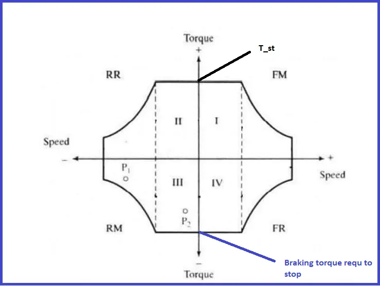
- The above plot is Speed-Torque of separately excited DC motor
Motor characteristics:
- Electric motors like brushed and brushless DC motor and induction motor will have high/enough starting torque at low speed,but as speed increases the the torque value will get reduced.
- Starting condition: At starting condition the speed is low but we have high starting torque as we shown in above condition in quadrant1.
- Braking Condition: At braking condition say at high speed we will have torue which is very low to stop the motor.
Electrical Braking
Rheostatic or dynamic braking:
In case of DC shunt motors, armature is disconnected from the supply and a rheostat (variable resistor) is connected across it. The field winding is left connected across the supply. Obviously, now armature is driven by the inertia and hence machine starts acting as a generator. Thus the machine will now feed the current to the connected rheostat and heat will dissipate at the rate of I2R. Braking effect is controlled by varying the resistance connected across the armature.
In case of DC series motor, motor is disconnected from the supply and field connections are reversed and a rheostat is connected in series. The field connections are reversed to make sure that the current through field winding will flow in the same direction as before.
Plugging or Reverse current braking:
In this method, armature connections are reversed and hence motor tends to run in opposite direction. Due to reversal of the armature terminals, applied voltage V and back emf Eb starts acting in the same direction and hence the total armature current exceeds. To limit this armature current a variable resistor is connected across the armature. This is similar for both series and shunt wound methods.
Plugging gives greater braking torque as compared to rheostatic braking. This method is generally used in controlling elevators, machine tools, printing presses etc.
Regenerative braking:
Regenerative braking is used where, load on the motor has very high inertia (e.g in electric trains). When applied voltage to the motor is reduced to less than back emf Eb, obviously armature current Ia will get reversed, and hence armature torque is reversed. Thus speed falls. As generated emf is greater than applied voltage (machine is acting as a DC generator), power will be returned to the line, this action is called as regeneration. Speed keeps falling, back emf Eb also falls until it becomes lower than applied voltage and direction of armature current again becomes opposite to Eb.
Note:
- In Dynamic and rehostatic braking the energy is dissipated in the form of heat across the rehostat,comparatively rehostat provide more braking torque than dynamic braking.
- In regenBraking we can transfer energy to the battery but this is achived when speed is greater than rated speed.
- Apart from these methods we have Mechanical friction braking.
Co-ordination of Electrical and Mechanical braking:
- Series Braking
- Paralle Braking
Series Braking:
In series braking both mechanical and electrical braking say regenerative braking/dynamic braking are applied alternatively.
The braking torque torque will be less when compare to Parallel braking
Parallel Braking:
In parallel braking both mechanical and electrical braking are applied at a same time to stop the vehicle.
The braking torque will be high in comparision with series brakig but regeneration will be less.
---------------------------------------------------------------------------------------------------------------------------------------------
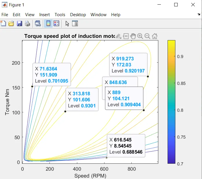
3.To create a contour plot for a motor.
- The efficiency of motor is given by efficiency = output/input power;
- output power = torque * speed
- input power = output power + losses
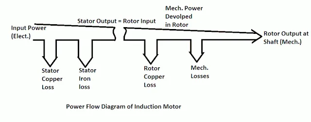
Losses in motor:
- Copper loss
- Iron loss/core loss
- Windage and friction loss
- Core losses: These include eddy current and hystersis losses in stator as well as in rotor magnetic core. Eddy current losses in rotor core are negligible since rotor current frequency is very small in the order of 0.5 to 2 Hz.
These losses of induction motor are constant since these depend upon voltage and frequency which is practically constant.
The hysteresis losses can be reduced by selecting a high permeability material for the core. The eddy current losses can be reduced by using the laminated cores instead of solid ones.
- Friction and windage losses: These losses are also constant losses as these losses depend upon the speed of the induction motor. The speed of the induction motor is approximately constant.

clc
clear all;

velocity = linspace(1,1000);   %velocity vector
Torque = linspace(1,250);      % torque vector


kc = 0.2;      % copperloss constabt
ki = 0.008;    % iron loss constant
kw = 0.00001;   % windage and friction loss constant
constL = 20;


[x y] = meshgrid(velocity,Torque);
outputPower = x .* y;

copperLoss = (y.^2).*kc;
ironLoss = (x.*ki);
windageLoss = (x.^3).*kw;

inputPower = outputPower + copperLoss + ironLoss + windageLoss + constL;
efficiency = outputPower./inputPower;
v = [0.7,0.75,0.8,0.85,0.875,0.90,0.91,0.92,0.93];


box off
grid off
contour(x,y,efficiency,v);
colorbar
xlabel('Speed (RPM)')
ylabel('Torque Nm')
zlabel('Efficiency')
title('Torque speed plot of induction motor with efficiency')


figure
surf(x,y,efficiency)
xlabel('Speed (RPM)')
ylabel('Torque Nm')
zlabel('Efficiency')
title('Efficiency values for various operating points of motor')