Week-11 Challenge: Braking
1.
aim: to calculate the energy required for braking for a defined driving cycle
explaination:
1. in order to calculate the energy required for a braking .consider a CYC_1015 driving cycle for calculation of the energy required for the braking
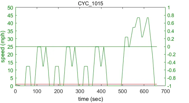
2. select a duration of 100 sec from the above driving cycle inorder to understand the braking energy calculations.select the driving region between 100 to 300 duration of time
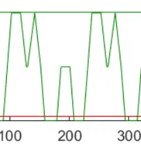
3. we know that
braking energy = 0.5* mass* `velocity^2`
= `1/2 *m*(Vi^2 -Vf^2)`
Vi = initial velocity
f = final velocity
4.use excel sheet calculation in order to perform analysis
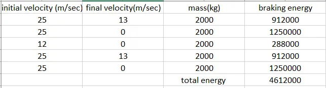
by implementing the above mentioned braking enegy farmula we can calculate the braking energy required for arious driving cycles.the total energy gives us the entire braking power required for the on driving cycle
conclusion:
in the advisor tool we can come across various driving cycles where the braking energy calculations can be performed with the uses of initial and final velocity of the cycle
2. Why electric motor can’t develop braking torque at high speed similar to starting?
explaination:
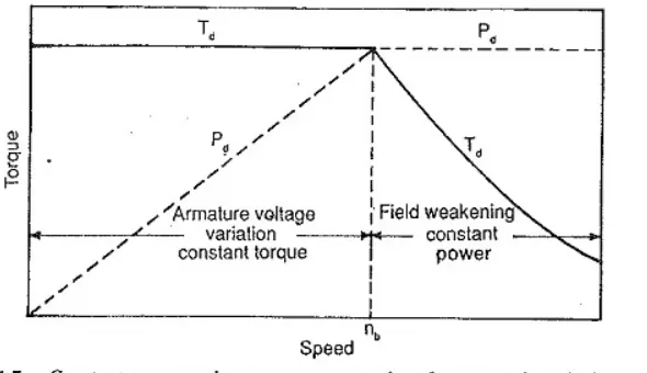
the graph represents the torque speed characterstic graph
we can observe two regions of the constant torque and power regions .with the increase in the speed torque remains constant foe a duration of time .if it reaches a critical speed then torque reduced gradually which indiacted by the constant power region
during the braking of the vehicle at high speed conditions .the torque is minimal so this torque need to incresed to the intial torque which is at the start of the vehicle so that vehicle requires more braking power at the high speed conditions
where as at the starting of the vehicle torque is more so that it is easy to stop the vehicle
How electric and mechanical brakes are coordinated?
explaination:
Mechanical braking system:
The mechanical braking system powers the hand brake or emergency brake. It is the type of braking system in which the brake force applied on the brake pedal is carried to the final brake drum or disc rotor by the various mechanical linkages like cylindrical rods, fulcrums, springs etc. In order to stop the vehicle.
Mechanical brakes were used in several old automobile vehicles but they are archaic nowadays due to their less effectiveness.
Types of Brakes:
DISC BRAKE
The disc brake is a mechanism for slowing or stopping the rotation of a wheel from its motion. A disc brake is normally made of cast iron, but in some cases, it is also made of composites such as carbon-carbon or ceramic -matrix composites. This is linked to the wheel and/or the axle. To stop the wheel, friction material in the form of brake pads is forced against both sides of the disc. Friction caused, on the disc wheel will slow or stop.
DRUM BRAKES
A drum brake is a traditional break in which the friction is caused by a set of shoes or pads that press against a rotating drum-shaped part called a brake drum.
The term \"drum brake\" usually means a brake in which shoes press on the inner surface of the drum. Where the drum is pinched between two shoes, similar to a standard disk brake , it is sometimes called a \"pinch drum brake\", although such brakes are relatively rare.
electric brakes:
Regenerative braking is an energy recovery mechanism that slows down a moving vehicle or object by converting its kinetic energy into a form that can be either used immediately or stored until needed. In this mechanism, the electric traction motor uses the vehicle's momentum to recover energy that would otherwise be lost to the brake discs as heat
coordination of both electric and mechanical brakes:
many of the EV and HEV vehicles uses this combination of brakes where this system contains conventional mechanical brakes such as frictional brakes and electric brakes such as regenerative brakes based on the front or rear wheel and speed of the vehicle these brakes are operated individually or combined
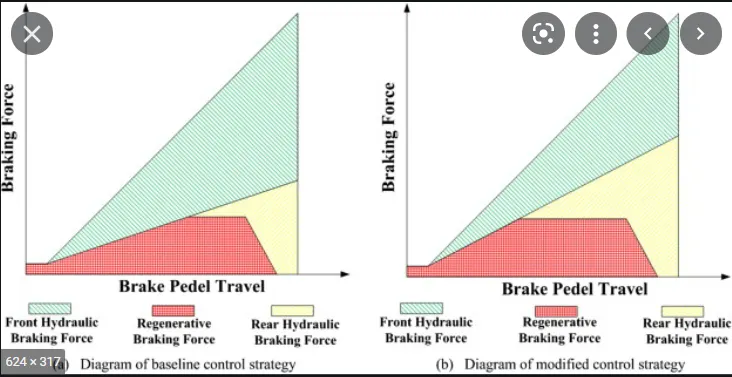
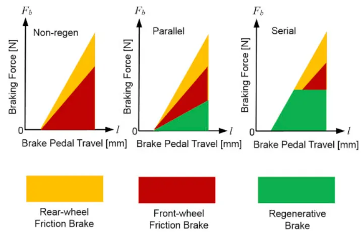
there are mainly two control stratagies
1.series control
in series control method brakes are applied one after other based on the speed and torque of the vehicle
2. parallel control
in this parallel control method both can be operated at a time
Electric Driven Intelligent Brake
EVs and hybrid vehicles use regenerative braking, which utilizes the motor to convert the kinetic energy during deceleration into electrical energy. With energy regeneration, an EV is able to run on less electricity and a hybrid vehicle on less fuel.
The EDIB (Electric Driven Intelligent Brake) allows and controls optimization of the regenerative brake and regular friction brake (hydraulic brake).
After stepping on the brake pedal, the system produces natural and adequate braking force that corresponds to the operation. The amount of energy regeneration also needs to be increased as much as possible.
EDIB (Electric Driven Intelligent Brake) controls the regenerative brake and friction brake to support both of these requirements. Further, it also controls the reactive force from the pedal in order to unify the feeling when stepping down on the pedal and the sense of deceleration.
When the driver steps on the brake pedal, the stroke sensor detects operation of the brake. That information is communicated to the ECU and controls the motor. The motor engages the piston and amplifies the friction brake's pressure (hydraulic pressure). Through optimum control of the friction brake's hydraulic pressure, the energy regeneration outcome is maximized.
3.
aim: to Make a MATLAB program which plots contour of given motor speed, torque and efficiency values. Attach the code as a .m file attach a screenshot of all the plots.
Explaination:
losses in the traction motors are due to the following factors such as
1. copper losses
= `i^2 *R` = `Kc * T^2` `
2. iron losses
= `Ki*omega`
3. windage losses
= `Kw*omega^3`
4. motor losses
=c
total losses = copper losses + iron losses + windage losses + motor losses
= `Kc * T^2 +Ki*omega+Kw*omega^3 +c`
input power = output power + total losses
efficiency = `(output power )/( inputpower)`
matlab script:
clc
clear all
close all

% consider an array of speed and torque values
speed= linspace(0,1000);
torque= linspace (0,250);

% constant losses in the motor

kc= 0.2; %copper losses
ki = 0.008;% iron losses
kw= 0.00001;% windage losses
cont_losses = 20;%motor losses

%mesh grid

[X,Y] =meshgrid(speed,torque);
outpower = (X.*Y);
B = (Y.^2)*kc;
C = X*ki;
D = (X.^3)*kw;
input_power = outpower+B + C + D + cont_losses ;
efficiency = outpower./input_power;

% efficencies for the contour
% label and plot the 2d plot

V = [0.70,0.80,0.85,0.90,0.91,0.92,0.925,0.93];
box off
hold on
contourf(X,Y,efficiency,V);
title('contour plot of speed ,torque and efficiency')
xlabel('speed/(rad/sec)')
ylabel('torque/(Nm)')
output:
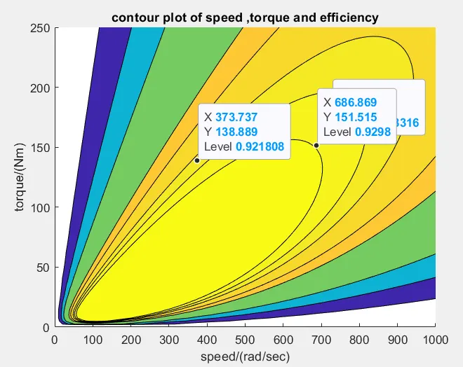
conclusion:
from the contour plot plotted between the speed and torque by considering the losses to the power generated to the output power . the heap of the plot gives the efficiency from the plot we can choose the efficiency of the we need to run so that sutiable torque and spped are adjusted as shown