Week-11 Challenge: Braking
1)For a defined driving cycle, calculate the energy required for braking.
Breaking energy= 1/2mv^2
Where
m=Mass (Vehicle +load)kg
V=initial-final velocity m/s
|
Velocity m/s |
kmph |
Mass |
Braking Energy |
|
|
0 |
0 |
5000 |
0 |
|
|
6 |
21.6 |
5000 |
90000 |
|
|
8 |
28.8 |
5000 |
160000 |
|
|
10 |
36 |
5000 |
250000 |
|
|
12 |
43.2 |
5000 |
360000 |
|
|
16 |
57.6 |
5000 |
640000 |
|
|
18 |
64.8 |
5000 |
810000 |
|
|
26 |
93.6 |
5000 |
1690000 |
|
|
28 |
100.8 |
5000 |
1960000 |
|
|
50 |
180 |
5000 |
6250000 |
|
|
60 |
216 |
5000 |
9000000 |
|
|
40 |
144 |
5000 |
4000000 |
|
|
30 |
108 |
5000 |
2250000 |
|
|
26 |
93.6 |
5000 |
1690000 |
|
|
20 |
72 |
5000 |
1000000 |
|
|
18 |
64.8 |
5000 |
810000 |
|
|
15 |
54 |
5000 |
562500 |
|
|
10 |
36 |
5000 |
250000 |
|
|
6 |
21.6 |
5000 |
90000 |
|
|
4 |
14.4 |
5000 |
40000 |
|
|
2 |
7.2 |
5000 |
10000 |
|
|
0 |
0 |
5000 |
0 |
|
|
total energy |
31912500 |
2)Why electric motor can’t develop braking torque at high speed similar to starting? How electric and mechanical brakes are coordinated?
i)Electric motor cant develop braking torque at hig speed because torque is inversely proportional to the square of the rotor speed therefore at high speed torque will be less.
ii)
there are four main braking modes: pure electric braking mode, motor and engine braking mode, motor and hydraulic braking mode, and hydraulic braking mode. In order to facilitate the kinetic analysis, the hybrid vehicle drive system model is simplified, as illustrated in Figure 5. where Je is moment of inertia of the engine; JISG is moment of inertia of the ISG; Jcvt is moment of inertia of the CVT; JC1 is moment of inertia of the clutch I; JC2 is moment of inertia of the clutch II; JPMSM is moment of inertia of the PMSM; Jw is moment of inertia of the wheel; JO1 is moment of inertia of the final drive I; JO2 is moment of inertia of the final drive II; m is the vehicle mass; r is the tire radius.
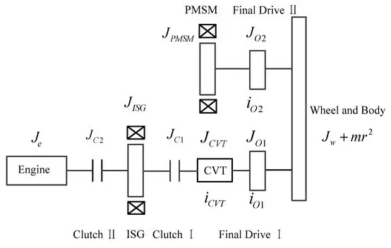
Figure 5. Equivalent diagram of the system model.
(1) Pure Electric Braking Mode
When the motor is braking clutch I is engaged and clutch II is disconnected. The engine and the hydraulic braking systems do not participate in the braking action and the required braking torque is provided by the motor. The equivalent to the moment of inertia on the wheel is:
Jv=((JISG+JC1)⋅icvt+JCVT)⋅iO1+JO1+JO2+JPMSM⋅iO2+Jw+mr2
(14)
The dynamic equation of braking is:
⎧⎩⎨⎪⎪TbICE=0Tbh=0TbISG⋅icvt⋅iO1+TbPMSM⋅iO2=Jvωw∙
(15)
where TbICE is the engine drag resistance torque, Tbh is the hydraulic braking torque, TbISG is the ISG braking torque, TbPMSM is the PMSM braking torque, and ω˙w is the wheel angular acceleration.
(2) Motor and Engine Braking Mode
When the motor and engine are involved in braking, clutches I and II are engaged. The required braking torque is provided by the motor and the engine. At this time, the equivalent to the moment of inertia on the wheel is:
Jv=((Je+JISG+JC1+JC2)⋅icvt+JCVT)⋅iO1+JO1+JO2+JPMSM⋅iO2+Jw+mr2
(16)
The dynamic equation of braking is:
{Tbh=0(TbISG+TbICE)⋅icvt⋅iO1+TbPMSM⋅iO2=Jvωw∙
(17)
(3) Motor and Hydraulic Braking Mode
During motor and hydraulic braking modes, clutch I is engaged and clutch II is disconnected. The required braking torque is provided by the motor and the hydraulic braking system. At this time, the equivalent to the moment of inertia on the wheel is:
Jv=((JISG+JC2)⋅icvt+JCVT)⋅iO1+JO1+JO2+JPMSM⋅iO2+Jw+mr2
(18)
The dynamic equation of braking is:
{TbICE=0TbISG⋅icvt⋅iO1+TbPMSM⋅iO2+Tbh=Jvωw∙
(19)
(4) Hydraulic Braking Mode
During hydraulic braking mode, clutches I and II are disengaged and the required braking torque is provided by the hydraulic braking system. The equivalent to the moment of inertia on the wheel is:
Jv=JCVT⋅iO1+JO1+JO2+JPMSM⋅iO2+Jw+mr2
(20)
The dynamic equation of braking is:
⎧⎩⎨⎪⎪TbICE=0TbISG=TbPMSM=0Tbh=Jvωw∙
(21)
Based on the kinetics analysis of the braking mode, there are three types of braking torque that need to be coordinated during braking mode switching. The motor, the hydraulic, and the engine braking systems are three different systems with different dynamic response characteristics; therefore, the sequences and moments of the three joint systems are different. Because mode switching is completed instantaneously, the braking torque varies sharply during the intervention and exit from braking. If there is no coordinated control, it will cause torque fluctuation and seriously worsen the ride comfort of the vehicle.
4.2. Coordination Control Strategy for Mode Switch
According to whether or not the hydraulic braking system is involved in braking, the braking mode-switch type is divided into two categories (Figure 6). Braking mode-switch coordination control strategies are developed for the different braking mode-switch types.
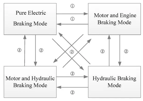
Figure 6. Braking mode switch classification.
(1) Type one: braking mode switch without hydraulic braking system participation. In this type of mode switching it is necessary to control the engagement of the clutch and the change rate of the motor torque. Thus, the fluctuation caused by mode switch can be reduced.
(2) Type two: braking mode switch with hydraulic braking system participation. Due to the different dynamic response characteristics of the motor and the hydraulic braking systems, this switch mode is difficult to coordinate. The idea of coordinating control is to take full advantage of the characteristics of the braking systems. The hydraulic system can provide large and stable torque, and the motor braking system’s torque response is quick and accurate, reducing the fluctuation of the vehicle.
The overall coordination control flow chart is shown in Figure 7. Tbm_req, Tbh_req and TbICE_req are the target motor, hydraulic and engine braking torques allocated by the braking force control strategy.
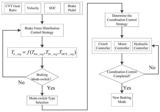
Figure 7. Flow chart of overall coordination control.
First, according to current speed, SOC, CVT ratio, and brake pedal, the braking force distribution control strategy allocates the target motor, hydraulic and engine braking torques; then, according to the braking mode boundary conditions the vehicle controller determines whether the braking mode should switch or not. If mode switching happens, the vehicle controller determines the type of mode switch and then selects the corresponding coordination control strategy and controls the clutch, motor and hydraulic torques to reduce the mode switch fluctuation. Finally, the vehicle controller determines whether the coordination control is completed, and if it is completed, the vehicle will enter a new braking mode.
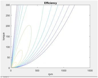
3)Make a MATLAB program which plots contour of given motor speed, torque and efficiency values. Attach the code as a .m file attach a screenshot of all the plots.
clc
clear all
close all
omega=Linspace(0,1500);
T=Linspace(0,200);
kc=0.2;
ki=0.0065;
kw=0.0001;
[X,Y]=meshgrid(omega,T);
copper_loss=(Y.^2)*kc;
iron_loss=X.*ki;
windage_loss=(X.^3)*kw;
con=25;
o_p=X*Y;
input_power=copper_loss+iron_loss+windage_loss+o_p;
eff=(o_p)./(input_power);
n=Linspace(0.65,0.95,10);
contour(X,Y,eff,n)
xlabel('rpm')
ylabel('torque')
title('Efficiency')