Week-11 Challenge: Braking
AIM: For a defined driving cycle, calculate the energy required for braking.
Drive Cycle: A driving cycle is a series of data points representing the speed of a vehicle versus time. Driving cycles are produced by different countries and organizations to assess the performance of vehicles in various ways, as for instance fuel consumption, electric vehicle autonomy and polluting emissions.
Braking: The function of the braking system is to retard the speed of the moving vehicle or bring it to rest in the shortest possible distance whenever required. The vehicle can be held on an inclined surface against the pull of gravity by the application of a brake. Brakes are mechanical devices for increasing the frictional resistance that retards the turning motion of the vehicle wheels. It absorbs either kinetic energy or potential energy or both while remaining in action and this absorbed energy appears in the form of heat. While moving down a steep gradient the vehicle is controlled by the application of brakes. In this case, brakes remain in action for a longer period making it imperative to dissipate the braking heat to the atmosphere as rapidly as possible.
Automobiles are fitted with two brakes; the service or foot brake and the emergency or hand brake. The foot brake is used to control the speed of the vehicle and to stop it, when and where desired, by the application of force on the brake pedal. The hand brake, applied by a lever, is used to keep the vehicle from moving when parked. Hand brakes are called emergency brakes because they are applied when the service brake fails. Virtually all vehicles are now equipment with 4-wheel brakes. The front brakes must operate without interfering with the steering action.The brakes must be capable of decelerating a vehicle at a faster rate than the engine is able to accelerate it. Normally brakes have to absorb three times the amount of engine horsepower energy in its equivalent form.
Kinetic energy is the force that keeps the vehicle moving. This energy is provided by the engine in order to accelerate the vehicle from a standstill to desired speed. Kinetic energy is dissipated as heat by the brakes during application of breaks.
Types of Energy on Moving Car: There are two kinetic types of energy that are involved in a moving car:
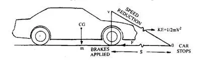
Linear and rotational kinetic energy- ` K_(e)=1/2mv^2 ; K_e =1/2Iω^2`
The deceleration from `V_1` to `V_2` will reduce the energy. This energy is being saved in hybrid and electrical cars as regenerative energy.
The linear energy change is equal to: `K_(e* chang)=1/2mv_1^2−1/2mv_2^2`
And rotational energy change is equal to: `K_(e* chang)=1/2I_1ω_2−1/2I_2ω_2`
And `V=rω=(dω)/2` and `ω=V/r` with r being the radius of the wheel, `r = d/2`.
However, because of small "I" of the wheels compared to the mass of the car, the contribution of the wheel's change of energy is not significant.
| Horsepower |
=
|
0.002667WdmaxS (or in SI units: Pb = m*amax*V) |
| 0.002667 |
=
|
constant factor to convert the metric SI units into Standard units |
| dmax |
=
|
maximum deceleration |
| S |
=
|
Speed of the car |
| Pb |
=
|
Power of brakes in Watts (= J/s = Nm/s = kgm²/s³) |
| m |
=
|
mass of car in kg |
| amax |
=
|
maximum deceleration in m/s² |
| V |
=
|
Velocity of car in m/s |
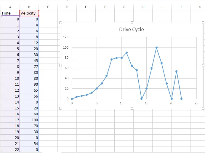
Drive Cycle In Excel Sheet: X-axis is Time and Y-axis is Velocity.
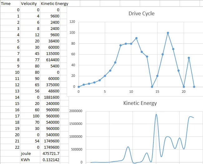
From Above sheet Calculation can be seen that Energy Required For Braking is 0.132kwh.
Power Required will be depending upon time at what time we want to stop vehice. let say In 10 sec we required to stop vehicle then power required is 0.132/10 = 47.58KW.
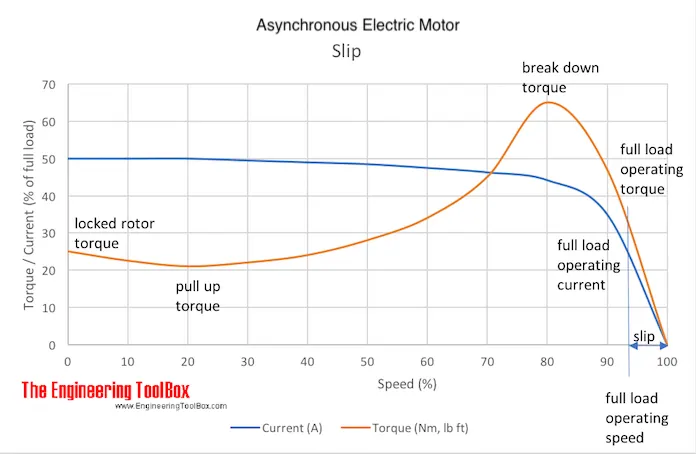
AIM: Why electric motor can’t develop braking torque at high speed similar to starting?
Electric mototr have high torque producing capability at low starting Speed, But as the speed increases the torque values rapidly decreases. Starting Torque - During the starting stage, the speed values are low and thus torque produced is much high. Braking Torque - In the braking stage, the speed of the motor is of very high value and sometimes greater the synchronous speed values, thus due to high speed values the braking torque generated will be a low value only.
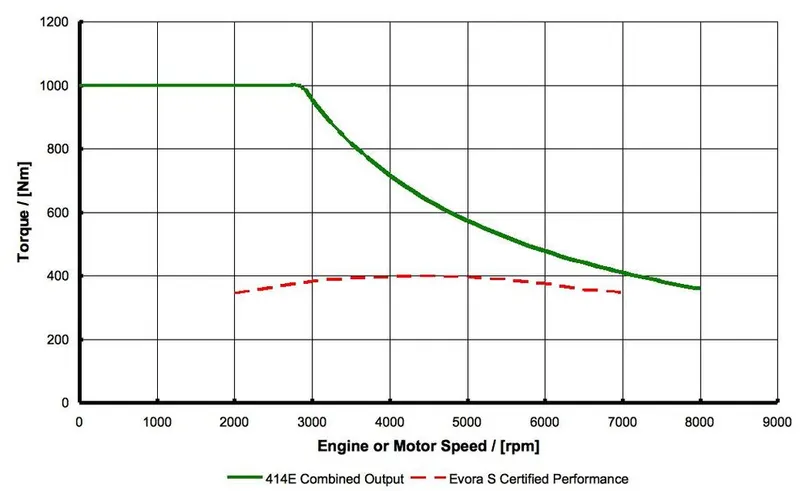
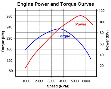
In Constant torque reason the Maximum torque will be constant and after increasing speed at surtain point(Depends upon motor design) Constant power reason start and torque started decreasig while speed increas.
Sometimes after accelerating you can't reach the maximum torque. The reason is that no matter how much the current loop wants to increase current (proportional to torque) by increasing the PWM duty cycle of the power stage, the Vmotor is too close to Vbemf and therefore current can't increase more.
Factors limiting the braking power generated during regenerative braking:
- Braking power is not only limited by the motor's power rating, but by the charging power limit of the battery pack. This limit depends on the battery type (chemical composition) and changes with temperature.
- The kinetic energy of a slowly moving car is low enough that very little energy is put back into the battery as the car comes to a stop. In fact, the last little bit of slowing the vehicle down generates such a small amount of energy that it does not even cover the fixed losses in the inverter and motor.
- Regenerative braking is necessarily limited when the batteries are fully charged. Because the additional charge from regenerative braking would cause the voltage of a full battery to rise above a safe level, the motor controller will limit regen torque in this case.
Other Reasons why the torque actual is NOT the real torque:
- If commutation, phasing, is not correct, an important part of the current is not useful torque, it just creates electrical and magnetic loses.
- If current loop is not well configured or unstable, the current will be higher and with ripple, the real "useful mechanical torque" will be indeed lower.
- Torque constant can vary due to several factors, like motor construction, temperature of the magnets (that affects its magnetic properties).
How electric and mechanical brakes are coordinated.
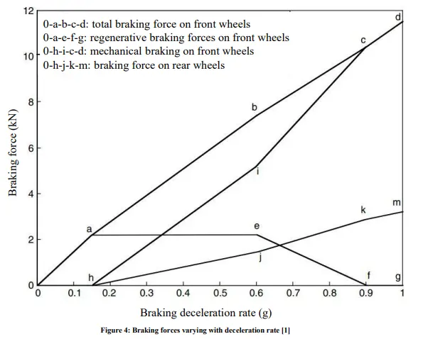
In a electric Motor the Total Brake distribution is in two aspects which are Electrical Brake which is called Regenerative Brake and Mechanical Brake or Classical Brake with hydraulic cylindrical system. Brake Force distribution must be uniform, If the Regenerative braking power requirement is more than the charging limit of the battery or more than regenerative capacity of the machine we must apply Mechanical brakes as well. In practical case the combination of these two is applied. So usually it is combined response of Mechanical brake and Regenerative brake. The reason for how these brake force are combined, that particular phenomena is called Brake Control Strategies.
Brake System of EVs and HEVs
- Series Brake — Optimal Feel
- Series Brake — Optimal Energy Recovery
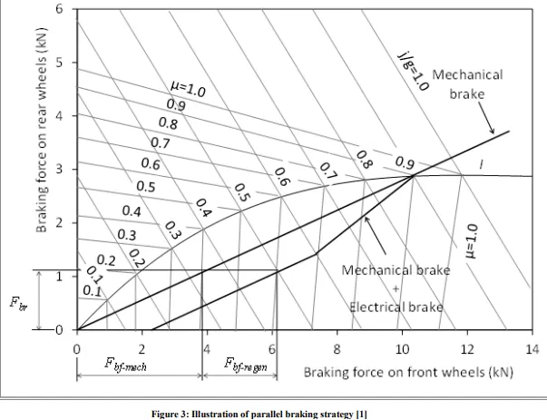
- Parallel Brake
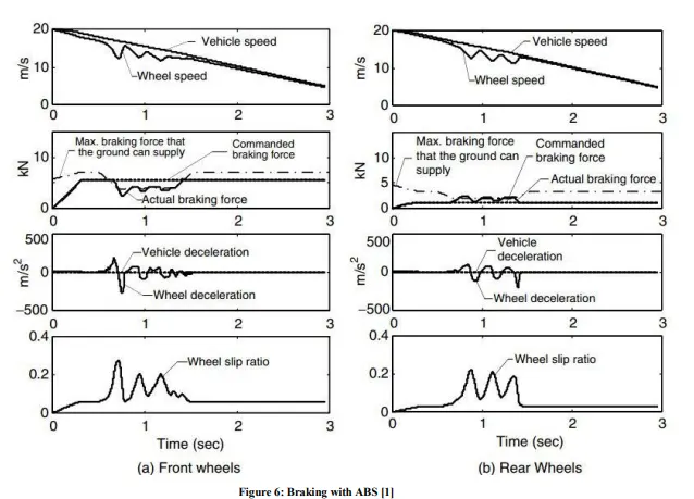
- Antilock Brake System (ABS)
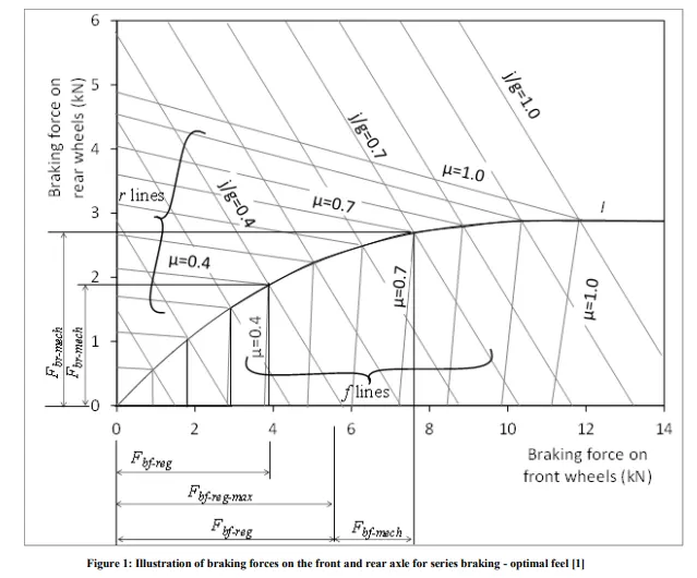
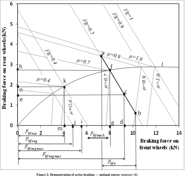
Generally Electric motor dont have high torque capacity to handle all of the vehicle braking. Hence during the initial braking time, mechanical brakes are used in larger proportion than regenerative braking.Once the braking torque value starts to decrease the regenerative braking is increased in proportion. Basically, there are three different brake control strategies: there series braking with optimal braking feel; series braking with optimal energy recovery; and parallel braking.
Series - In case of Series we apply Mechanical brake and Regenerative electric brake one after another. We can apply only one brake strategy at a time either apply Regenerative or apply Mechanical brake. The Series Brake Control Strategy has further classification, that is based on whether we want comfort of driver or Brake behaviour compared to energy efficiency.
Parallel - In case of Parallel we apply both brakes simultaneously. This Particular Parallel braking is going to happen both at a time. Electric Driven Intelligent Brake (EDIB) is a combination of Hydraulic brake or Mechanical brake along with a Regenerative brake. It is a Parallel braking technique. The Control criteria such that at low speed use regenerative braking higher and at high speed or during initial braking period we actually combine the both.
Antilock Brake System (ABS): Active control of the braking force (torque) of the electric motor is easier than the control of the mechanical braking force. Thus, antilock in braking with an electric brake in EVs and HEVs is another inherent advantage, especially for a vehicle with an electric motor on four wheels.
AIM: Make a MATLAB program which plots contour of given motor speed, torque and efficiency values. Attach the code as a .m file attach a screenshot of all the plots.
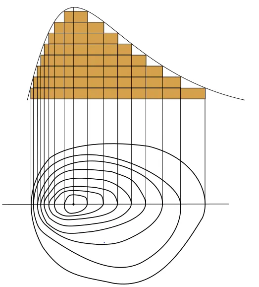
What is Counter: A contour line of a function of two variables is a curve along which the function has a constant value, so that the curve joins points of equal value. It is a plane section of the three-dimensional graph of the function f parallel to the-plane.
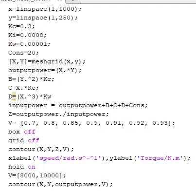
Matlab Script:
x=linspace(1,1000);
y=linspace(1,250);
Kc=0.2;
Ki=0.0008;
Kw=0.00001;
Cons=20;
[X,Y]=meshgrid(x,y);
outputpower=(X.*Y);
B=(Y.^2)*Kc;
C=X.*Kc;
D=(X.^3)*Kw
inputpower = outputpower+B+C+D+Cons;
Z=outputpower./inputpower;
V= [0.7, 0.8, 0.85, 0.9, 0.91, 0.92, 0.93];
box off
grid off
contour(X,Y,Z,V);
xlabel('speed/rad.s^-^1'),ylabel('Torque/N.m');
hold on
V=[8000,10000];
contour(X,Y,outputpower,V);
Counter Plot:
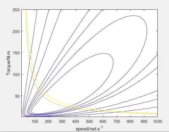
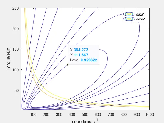
Explanation for above Program & Steps:
- Assign Input of Speed and Torque in an array using 'linspace' Command and allocate Constant Values for four losses(Copper Loss, Iron Loss, Windage Loss and Constant Motor Loss).
- Mesh the Speed and Torque values using 'meshgrid' command.
- Calculate the Output Power by multiplying Speed and Torque values.
- Calculate Copper Loss, Iron Loss, Windage Loss using those formulas.
- Calculating Inputpower by adding Output Power and Four Losses(Copper Loss, Iron Loss, Windage Loss and Constant Motor Loss).
- The ratio of Output Power and Input Power we can get the Efficiency.
- Now Set the Efficiencies for which a contour will be plotted. The range of contour efficiency is to plot from 70% to 93% efficiency. V is the Mapping of those efficiency points.
- Plot the Contour Efficiency using 'contour' command and plot Speed,Torque,Efficiency and V. Contour : contour(Z) creates a contour plot containing the isolines of matrix Z, where Z contains height values on the x-y plane. MATLAB automatically selects the contour lines to display. The column and row indices of Z are the x and y coordinates in the plane, respectively. 'contour(X,Y,Z)' specifies the x and y coordinates for the values in Z.
- Now plot a contour of Power Output. Plotting contour of 8kw and 10kw of a Motor.
- Run the Program and get the Motor Speed-Torque Efficiency Contour Plot.