Week - 4
AIM: Implement control logic of a “washing machine” using Stateflow as per given sequence
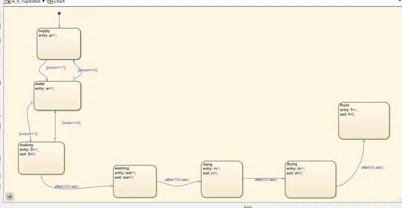
If the power supply is available, the system gets activated
If the Water supply is not available, stop the process & indicate through LED
Soaking time should be 200s followed by Washing time of 100s.
Then rinsing happens for next 20s & dryer runs for 50s.
WASHING MACHINE: A washing machine is a machine that washes dirty clothes. The barrel is filled with water, and then rotated very quickly to make the water remove dirt from the clothes. Most washing machines are made so that detergent
(liquids or powders) can be put into the machine. It can handle various tasks like soaking, washing, rinsing, drying within a short period of time.
STATEFLOW: statefloe provides a graphical language that includes state transition diagrams, flow charts, state transition tables, and truth tables. With Stateflow, you model combinatorial and sequential decision logic that can be simulated as a block within a Simulink model or executed as an object in MATLAB.
control logic: controls the operations of the program. The control logic responds to commands from the user, and it also acts on its own to perform automated tasks that have been structured into the program.
Given condition:
soaking for 200 sec
washing for 100 sec
rising for 20 sec
drying for 50 sec
State flow:
Symbol pane:
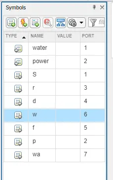
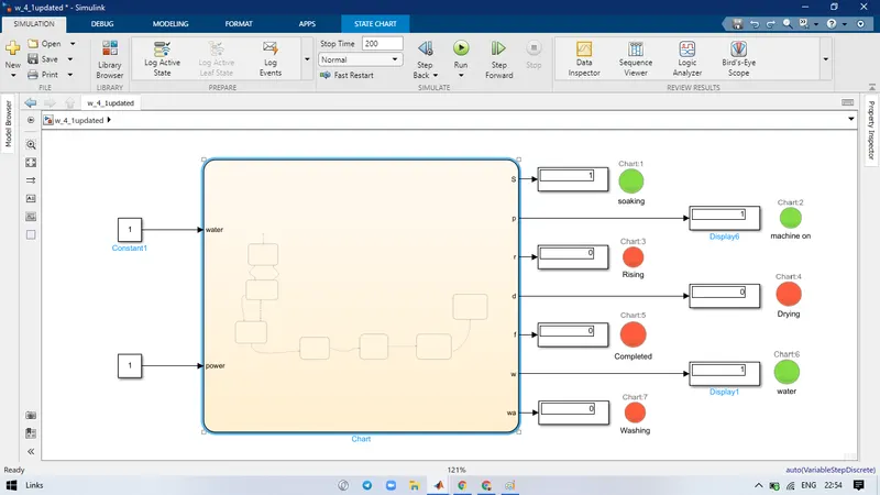
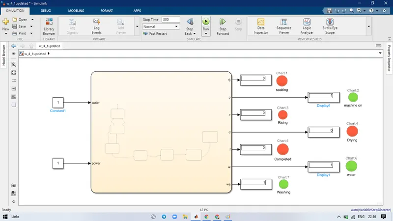
First input port are power and water when these are equal to 1 then futher conditins follows otherwise machine off
- Power input 1 then check for water supply
- If water supply given i.e. 1 then soaking start
- Soaking will run for 200 sec for that soacking is ON indicated by Soaking LAMP
- After Soaking Washing is ON for 100 sec and indicated by Washing LAMP
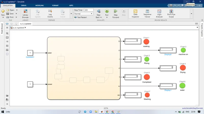
- Rinsing will start for 20 sec and LAMP will indicate that.
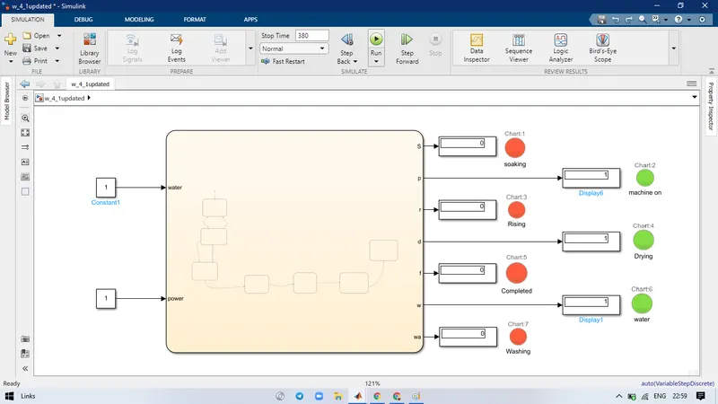
- Drying will start for 50 sec and indicated by lamp and process finish.
SOAKING
WASHING
RINSING
DRYING
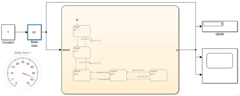
AIM: Make a Simulink chart for the “Gear shift” logic as per below conditions:
Speed Range(kmph) Gear
0 to 15 1
16 to 25 2
26 to 40 3
41 to 60 4
Above 61 5
Give speed input while the simulation is running & display the gear number.
Gear: The gears determine the amount of power available from the engine. First gear provides the most pulling power but the least potential for speed, whilst fifth gear which provides the least pulling power allows the greatest range of speed.
MODEL:
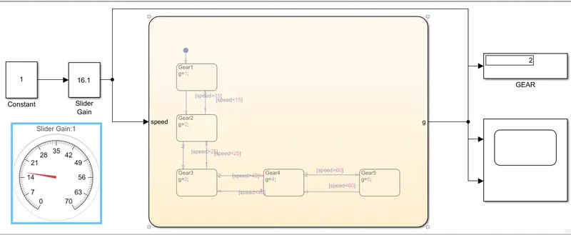
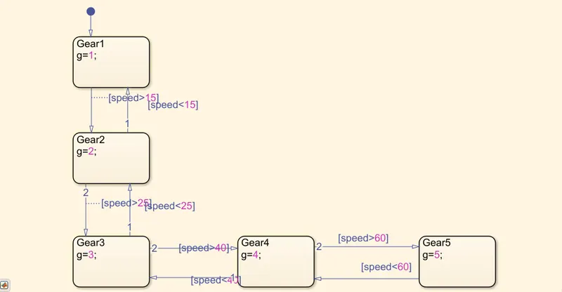
STATE FLOW
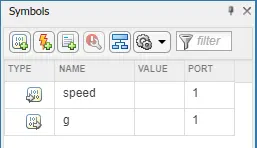
SYMBOLS:
Speed is taken as input
G is taken as output which is Gear
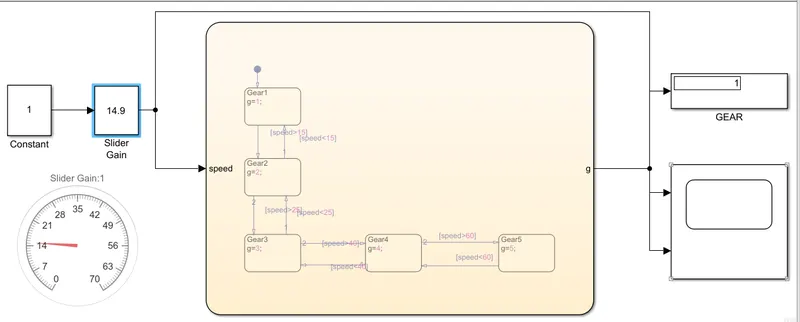
Procedure: In chart given condition is for every given speed Gear should be change this will posible by using chart/state flow.
The condition of stateflow is given to show output as G1, G2, G3, G4, G5.
At GEAR 1: Range 0-15
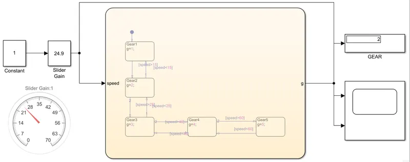
At GEAR 2: Range 16-25
At GEAR 3: Range 26-40
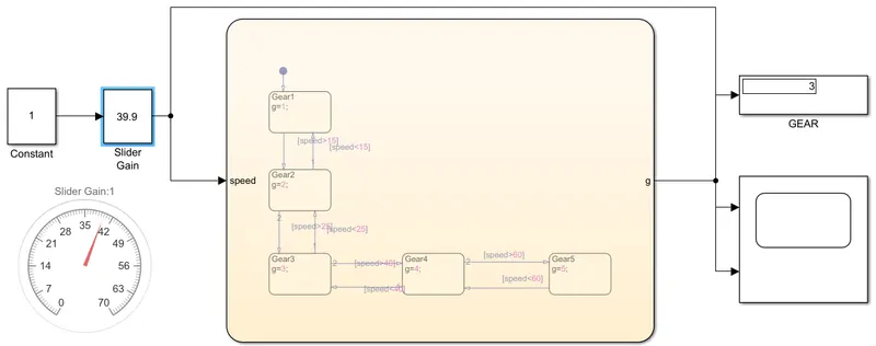
At GEAR 4: Range 41-60
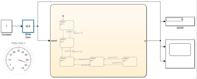
At GEAR 5: Range above 61