Week-6 Challenge: EV Drivetrain
AIM: Which types of power converter circuits are employed in electric and hybrid electric vehicle.
Power Electronics in EV: The power converter is made of high power fast-acting semiconductors devices, such as a bipolar junction transistor. There are some other transistors such as MOSFET, IGBT, SCR, GTO, MCT. These devices are used as on-off electronics switch to convert the fixed supply voltage into a variable voltage and variable frequency supply. Power Electronic Converters (PECs) not only serve the purpose of converting electrical power from one form to another (DC/DC, DC/AC and, AC/DC) but also help to step up or step down the system voltage level. In the last decade, significant advancement in converter topologies dealing with battery charger, voltage source inverter for motor drives and DC/DC conversion has been achieved. Regardless of this topological advancement, still conventional PEC topologies are being used in modern electrified vehicles.
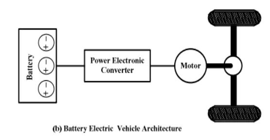
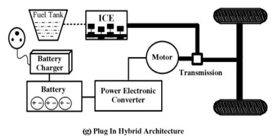
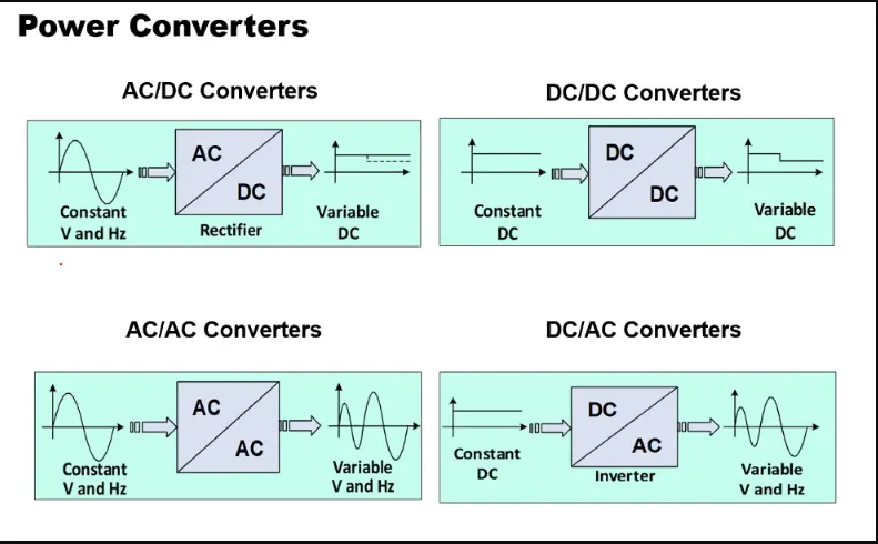
Power Converter Circuits:
- DC/DC Converters: Also called as Chopper, its basic form converts unregulated DC input voltage at a certain level to a regulated DC output voltage at a different level with very high conversion efficiency (>90%). Modern day DC/DC converters are operated at high frequencies (10 kHz - 1 MHz). The size of the components such as inductors, transformers, and capacitors are reduced at high frequency operation. Transistors such as MOSFETs and IGBTs are used as switches. DC/DC Converters used for boosting the Battery Voltage and DC Motor Drives.
Examples of DC/DC Converter: PWM DC/DC Converter, Zero Voltage Switching Multi Resonant Converter, Const. Freq. Quasi Resonant & Multi Resonant Converter, Nonlinear Switch Converter, Resonant Converters, Soft Switching PWM Converter & ZVS/ZCS PWM Converters, etc.
For Boosting Battery Voltage: Non isolated Bidirectional H-bridge Converter, Interleaved DC/DC Converters, Isolated Bidirectional Full Bridge Converter, etc.
For DC Moto Drives: Two Quadrant ZVS MR Converte, Two Quadrant ZVT Converter, Two Quadrant ZCT Converter, etc.
- DC/AC Converters: A suitable DC/AC inverter draws DC power from the batteries to drive the electric traction motor, which in turn provides power to the wheels. The DC/AC inverter alsoperforms the function of recharging the batteries during regenerative braking in
HEVs. Also, Inverters are used for supplying utility loads such as Air conditioning and power outlets. Inverters are generally classified into voltage-fed and current-fed types. DC/AC Converter used for Charging and Power Factor Correction (PFC) which hepls to decreasing the empact on grid and switches.
Examples of DC/AC Converters: H-bridge Technology with Single DC Link, Soft Switched Inverters, Multi-Level Inverters, Z-Source Inverter, etc.
- AC/DC Convertes: 2. The AC/DC converter consists of a power factor correction (PFC) which converts input AC voltage into DC voltage, an H-bridge circuit which converts the DC voltage into high-frequency AC voltage, a high-frequency transformer which regulates transformation and insulation, and a circuit which rectifies and smooths high-frequency AC voltage. This Converter used for Charging and Power Factor Correction (PFC) which hepls to decreasing the empact on grid and switches.
For Charging EV: Unidirectional full-bridge series resonant converter, Nonisolated bidirectional two-quadrant, Isolated bidirectional dual active bridge, etc.
- AC/AC Converters: They not used in EV and they gives variable frequencies output and voltage at variable inputs. They are used in Induction Motor control like Fan.
Examples: Cycloconverter, AC to AC convert with DC Link, Matrix Converter, Hybrid Matrix Converter.
AIM: An Electric Vehicle's powertrain with 72V battery pack in shown in the diagram below. The duty ratio for acceleration operation is 'd1' and for the braking operation the duty ratio is 'd2'.
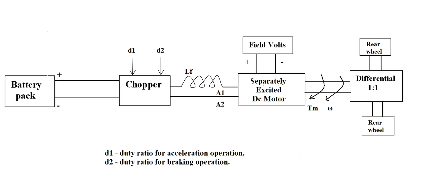
The other parameters of the electric vehicle is given below,
Given, Motor and Controller Parameters:
Rated Armature voltage= 72 V
Rated armature current= 400 A
Ra= 0.5Ω, KΦ= 0.7 Volt second
Chopper Switching frequency= 400 Hz
The vehicle speed-torque characteristics are given by the below equation

What is EV steady state speed if duty cycle is 70%.
We, know the Torque(Te) -Speed (Wn)Relation = `V/(k'*phi)-(Ra*Te )/(k'*phi)^2`
Torque = `(V*K'*phi )/(Ra) -(W(K'*phi)^2)/(Ra)`
Te - Torque
K' - Constant
Φ - Flux
V - Supply Voltage
Ra - Armature resistance
So, the average voltage is given by the product of the battery voltage and the duty cycle:
Vo = V*DC
V = 72*0.7
Now, The average voltage is 50.4V.
Put all values in Torque formula-
Te = `(50.4*0.7)/(0.5)-(Wn *(0.7)^2)/(0.5)`
Te = `70.56- (0.98*omega)`
Tv = `24.7 + (0.0051)omega^2`
Compare this Formulas -
`45.86-0.98*omega-0.0051*omega^2=0`

So, value of W is 38.91 & -231.07 Rad/sec
So, the value of W is 38.91 rad/sec
AIM: Develop a mathematical model of a DC Motor for the below equation using Simulink.
ω">ω= V/Kϕ">ϕ -Ra/Kϕ">ϕ^2 .T
Simulink Model:
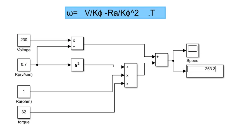
Block Used:
Constant, Square, Adder, Substractor, Scope.
AIM: Refer to the blog on below topic: Induction Versus DC brushless motors by Wally Rippel, Tesla
Author’s perspective: Back when there were lead acid batteries, DC brush motors, and contactor controllers. Today, none of these remain, Lead has been replaced by lithium and DC by either DC brushless or induction. Contactors, to modulating inverters. Author say as technology advanced nothing will remain constant. As we understand the engines from their types based on their performance and price similarly, the EV drives also has different types of motor and drive train according to utility.After comparing both he finally conclude with that the plug in and Hybrid vehicle market will be dominated by DC brushless and the induction motor will drive the high-performance pure electrics so they both will have their major significance in this coming golden era of hybrid and electric vehicles .
DC brushless drives will likely continue to dominate in the hybrid and coming plug-in hybrid markets, and that induction drives will likely maintain dominance for the high-performance pure electrics. The question is what will happen as hybrids become more electrically intensive and as their performance levels increase? The fact that so much of the hardware is common for both drives could mean that we will see induction and DC brushless live and work side by side during the coming golden era of hybrid and electric vehicles.
According to him we should talk about utility of these motors rather than best one of them. So Author Discuss what are these two technologies, How do they work, What differentiates them, And what do they have in common.
| Similarities | Differences |
| The stators for the 3-phase induction motor and the DC brushless motor are virtually identical. | Unlike DC brushless rotor, the induction rotor has no magnets.just stacked steel laminations with buried peripheral conductors that form a “shorted structure.” |
| Both have three sets of “distributed windings” that are inserted within the stator core. | The essential difference between the two machines is with the rotor. |
| One of the main differences is that much less rotor heat is generated with the DC brushless drive. | Slip causes decreas in rotor speed in induction motor unlike BLDC |
|
Both drives use 3-phase modulating inverters. |
The only differences are the rotors and the inverter controls. DC brushless drives require an absolute position sensor, while induction drives require only a speed sensor; these differences are relatively small. |
| Advantege of BLDC over Induction Motor | Advantage Induction Motor over BLDC |
| Much less rotor heat is generated with the DC brushless drive. Peak efficiency will be a little higher than with induction motor. | Induction machines have no magnets and magnetic fields are adjustable V/f. |
| Brushless DC motor produces no starting torque when directly connected to fixed frequency utility power. | DC brushless, as machine size grows, the magnetic losses increase proportionately and part load efficiency drops. |
| Rotor cooling is easier and peak point efficiency is generally higher for this drive | With induction, as machine size increases losses do not necessarily increases. Thus, induction drives may be the favored approach where high-performance is desired. |
| The DC brushless drive can also operate at unity power factor, whereas the best power factor for the induction drive is about 85 percent. | Induction motors will likely retain a cost advantage over PM machines. Due to the field weakening capabilities of induction machines, inverter ratings and costs appear to be lower |
| As BLDC have permanent magnet they don't have Eddy and hysteresis losses but | They don't have recurring costs. |
| The peak point energy efficiency for a DC brushless drive will typically be a few percentage points higher than for an induction drive. | Peak efficiency will be a little less than with DC brushless, but average efficiency may actually be better. |
| Induction machines are more difficult to control. as the control laws are more complex and difficult to understand | With varryinng load efficiency will be greater than BLDC motor as inverts helps. |