- For a defined driving cycle, calculate the energy required for braking.
sol:
workdone=kinetic energy
for calculating energy formula is E=0.5m*v^2
m=mass of the vechile=1000kg
v=velocity of the vechile
vf=vi vehicle is going from 100 to 0
vf=final velocity and vi=inital velocity
t=time required from 100 to 0 =10sec
power required is P=E/t
`p=(0.5*1000*(100*0.277)^2)/10)`=38.36kw
energy required for for braking from 100 to 0 speed in 10sec is E=0.0106KWHR
for 100 to 0 in 1 sec is E=0.106kwhr
(2)Why electric motor can’t develop braking torque at high speed similar to starting? How electric and mechanical brakes are coordinated?
The braking torque in a electric motor is not as high as of acceleration torque at higher speeds.this can be due to,rate of
discharge of battery is higher than the charging rate.there are other limitations to thermotors in the form of power converters to,this is customized in three phase inverters which are bi directional as it needs to convert regenartive braking energyback to dc current for the battery and it reduces the efficiency of power converter at low speeds braking is very high speed increases.the braking reduces resulting in reduced braking toruqe.hence for braking at high speeds we use a combination of hydraulic and regenrative brake
1. Plugging: The three phase voltage sequence is reversed at the stator terminals of the induction motor. The equivalent form of plugging in dc drive systems is the reversal of the polarity of the armature voltage of a dc motor.
2. DC Injection Braking: A d.c. voltage is applied to any two of the three terminals of the induction motor.
3. Eddy Current Braking: A separate eddy current braking device is coupled to the shaft of the motor. Eddy current braking results when electromagnets are activated and they induce eddy currents in the rotating metallic disk. The eddy
currents produce magnetic fluxes that oppose the flux produced by the electromagnets and thus result in a braking torque on the motor. The energy
is dissipated as heat in the rotating metallic disk.
1. It can be stored in batteries.
2. It can be stored in a flywheel (a flywheel that has an integrated permanent
magnet dc alternator).
3. It can be returned to the ac supply using a regenerative drive.
mechanical braking:
1. Drum brakes.
2. Disk brakes.
3. Band brakes.
4. Pawl and Ratchet brakes: The ratchet is linked to a spring loaded friction
plate. The ratchet is lifted using a solenoid.
The drum and disk brakes are either electromagnetically lifted or hydraulically lifted, but always spring applied. They must be spring applied for safety reasons, so that when the power supply is lost, the brake will apply and safely bring the load to a standstill
Comparison between Electrical and Mechanical Braking Systems
The following is a comparison between electrical and mechanical braking systems:
a. Electrical braking systems are used for functional braking (controlling the speed; bringing the load to standstill). Mechanical braking systems are used for emergency stopping or for parking.
b. Electrical braking is usually very smooth and comfortable. Mechanical braking is usually rough and uncomfortable.
c. No wear results from electrical braking. Mechanical braking on the other hand causes wear in the braking components and requires regular maintenance.
d. It is possible (but not always feasible) in electrical braking systems to return the regenerated energy back to main supply. This is not possible in mechanical braking systems and the energy is always lost as heat, noise and
wear.
e. The electrical braking system cannot be used as a safety device. Most systems will require a mechanical braking system as a backup safety device.
(3)Make a MATLAB program which plots contour of given motor speed, torque and efficiency values. Attach the code as a .m file attach a screenshot of all the plots.
equation:
power=speed*torque
copper loss=cu=kc.t^2
iron loss=I=ki*w
windage loss=w=kw.w^3
consatnt=c
where w=speed
t=torque
kc=copper loss
ki=iron loss
kw=windage loss
input:
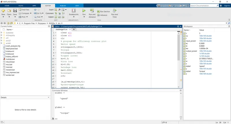
clear all
close all
clc
% program for efficiency countour plot
%motor speed
s=linspace(0,1300);
%torque
t=linspace(0,250);
%copper losses
kc=0.3;
%iron loss
ki=0.08;
%windage loss
kw=0.0001;
%constant
c=5;

[x,y]=meshgrid(s,t);
%power=speed*torque
output_power=(x.*y);
%copper loss
cu=kc.*(y .^2);
%iron loss
I=ki.*x;
%windage loss
w=kw.*(x.^3);

%input power
input_power=output_power+cu+I+w+c
%efficiency
z=output_power./input_power;

%plotting
v=[0.70,0.75,0.80,0.85,0.90,0.95];
contour(x,y,z,v)
grid on;
xlabel=('speed')
ylabel=('torque')
plot:
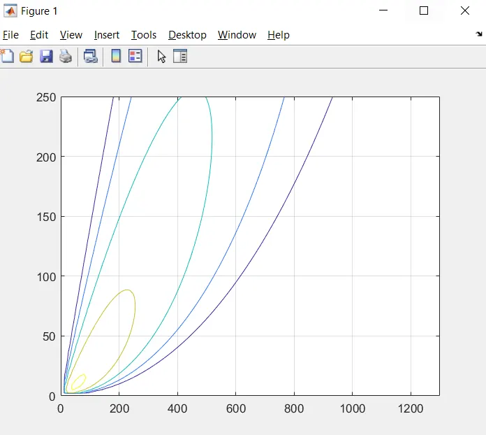
procedure:
giving input of motor and array values
giving the losses of windage,copper,iron
calculating output power,windage,copper,iron
calculating the input power
calculating the efficiency
plotting with the required labels