Week-11 Challenge: Braking
WEEK 11 CHALLENGE
- For a defined driving cycle, calculate the energy required for braking.
Ans.
There are two kinetic types of energy that are involved in a moving car:
Linear and rotational kinetic energy,
Ke linear=1/2 *Mv2 ;
Ke rotatinal=1/2*Iω2
The deceleration from V1 to V2 will reduce the energy. This energy is being saved in hybrid and electrical cars as regenerative energy.
The linear energy change is equal to:
Ke linear change=1/2*Mv12−1/2*Mv22
And rotational energy change is equal to:
Ke rotational change =1/2*I1 ω2 −1/2*I2 ω2
And V=rω=dω/2 and ω=V/r V=rω=dω/2 and ω=V/r with r being the radius of the wheel, r = d/2.
However, because of small "I" of the wheels compared to the mass of the car, the contribution of the wheel's change of energy is not significant.
Hence, let us only consider energy due to Linear change in kinetic energy.
First, we need to create an excel sheet which contains the drive cycle of the vehicle.
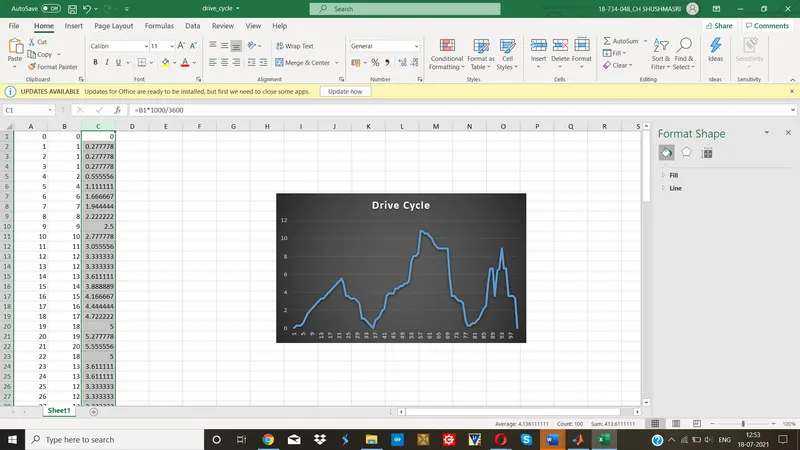
The first column in Excel sheet is time, the second column is speed in Kmph and third colum is speed in m/s which is calculated from column 2 by multiplying with the factor 1000/3600. The drice cycle plot is shown in the chart.
This excel file should be imported to MATLAB.
This can be done by clicking Import Data in MATLAB and choose Drivecycle.xlsx. Select all and click on Import selection.We observe that 99x3 table is added to workspace.
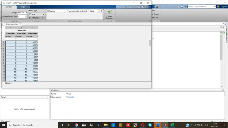
Then write the program for calculating energy required for braking.
Let the mass of the vehicle be 700kg.
MATLAB Code:
m=700;
t=drivecycle(:,1);
v=drivecycle(:,3);
Eb=ones(1,99);
if istable(v), v=table2array(v); end
for i=1:98
if v(i)>v(i+1)
Eb(i)=0.5*m*(v(i)-v(i+1))^2;
end
end
fprintf("Total brake energy:%d\n",sum(Eb));
fprintf("Average brake energy:%d\n",mean(Eb));
figure(1)
subplot(2,1,1)
plot(v)
xlabel("time(s)");
ylabel("Velocity(m/s)");
title("Drive Cycle");
subplot(2,1,2)
plot(Eb)
xlabel("time(s)");
ylabel("Braking Energy(W)");
title("Braking Energy");
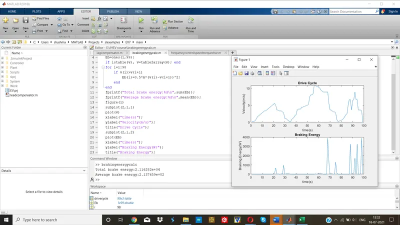
The braking energy is calculated whenever these is a fall in speed. When speed decreases, deceleration takes place and a spike is observed in the plot.
From results:
The total energy required for braking is 21.162kW
The average energy used for braking is 213.766W.
https://drive.google.com/file/d/1fH_JuhtSjFCtxyuANYrvyamsW8EYE5Xy/view?usp=sharing
2. Why electric motor can’t develop braking torque at high speed similar to starting? How electric and mechanical brakes are coordinated?
Ans.
When motor is at rest and it has to operate from standstill position to reach the moderate speed, the higher torque is required to bring to motor operation. Whereas when the vehicle is already at high speed the capping or limit is reached by the motor operation and thus further higher torque could not be obtained while braking. The braking operation happens in the motion which is been distributed as per proportion in the brake energy and the regenerative braking. Hence, Electric motor can’t develop braking torque at high speed similar to starting.
ELECTRIC BRAKES AND MECHANICAL BRAKES COORDINATION:
The electro-hydraulic braking system of hybrid electric vehicles consists of the regenerative braking system (motor braking system), vehicle hydraulic braking system, and engine braking system. Hence, the braking process of hybrid electric vehicles is a dynamic process which is influenced by a synthesis of multiple parameters and multi-system interactions. The characteristics of electro-hydraulic braking systems have a direct influence on the fuel consumption, emissions, braking safety, and ride comfort of hybrid electric vehicles.
The schematic diagram of a hybrid electro-hydraulic braking system is shown in figure
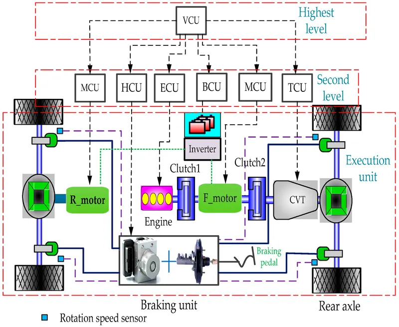
The vehicle collects gathers the signals of braking pedal displacement, vehicle speed, continuously variable transmission (CVT) ratio, battery state of charge (SOC), and other signals through the controller area network (CAN) bus, and subsequently calculates the required motor braking force and hydraulic braking force. The required motor and hydraulic braking force signals are sent to the Hydraulic Control Unit (HCU) and Motor Control Unit (MCU) for braking force control through the CAN bus.
The system braking modes include conventional braking and regenerative braking. The control flowchart of the braking system is shown below, where Ff_reg_max and Fr_reg_max denote the maximum braking forces of the front and rear motors, respectively, Freq denotes the required braking force.
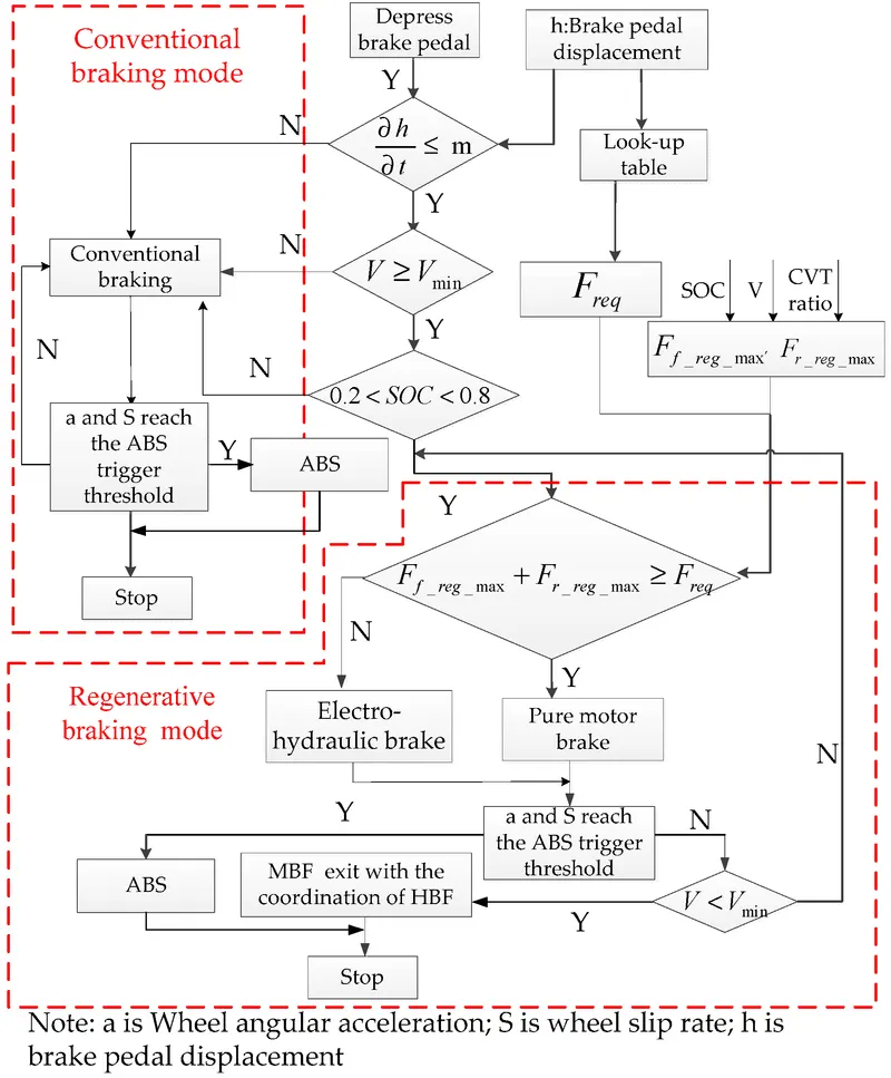
When the emergency braking is applied, the vehicle speed is too low, or the battery is not suitable for charging, the system works in conventional braking mode; thus, the braking force is only provided by the master cylinder, and the front and rear axle hydraulic braking forces are distributed in accordance with the traditional β-line (β denotes the braking force distribution coefficient. β-line denotes the braking force distribution curve of front and rear brakes) as shown in Equations below
Fr_h=βFb_req
Fr_h=(1−β)Fb_req
Fb_req=Gz
When none of the above conditions is satisfied, the system works in regenerative braking mode. The regenerative braking system attempts to maximize the energy recovery rate under the premise of ensuring braking safety. The braking force distribution strategy has an important influence on the energy recovery rate of the regenerative braking system. Considering that the hybrid electric vehicle has two motors and the transmission efficiency of the rear axle is higher than that of the front axle, the braking force is provided priority by the rear motor, the remaining part is provided by the front motor. In addition, the front motor braking force can be magnified by adjusting the CVT ratio so that the front motor braking force can be fully utilized. When the front and rear motor braking force is insufficient, the hydraulic braking force is added as a supplement.
The detailed braking force control of the electro-hydraulic braking system is shown in figure below
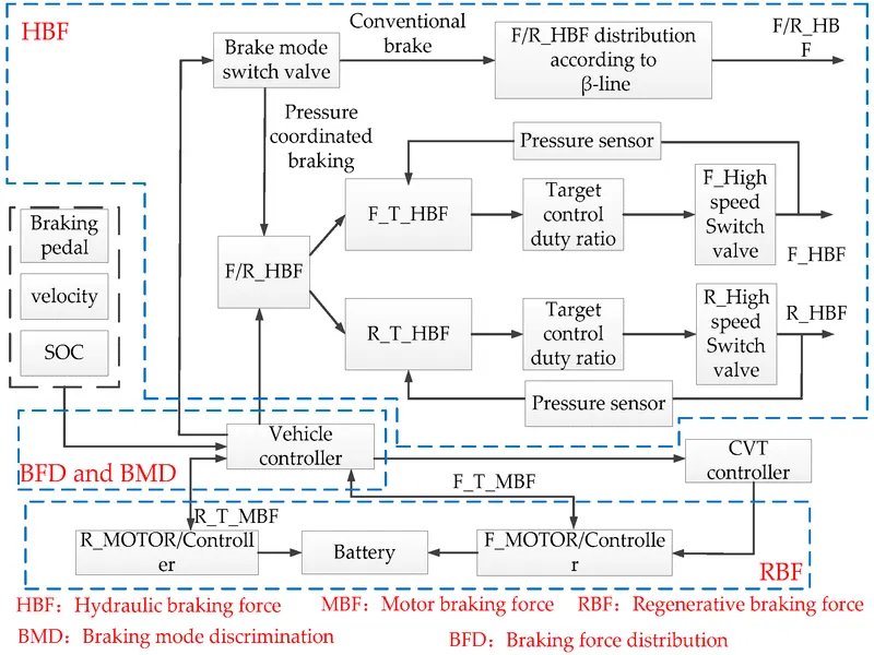
When the driver depresses the braking pedal, the vehicle controller obtains the braking pedal signal, vehicle speed signal, and SOC signal to determine the braking mode and thereafter operates the pressure coordinated control system in the traditional braking mode or pressure coordinated braking mode by controlling the mode switch valve. When the system is operated in the conventional braking mode, the front and rear axle hydraulic braking forces are distributed in accordance with the traditional β-line and the motor does not apply the brake. When the system is operated in the regenerative braking mode, the vehicle controller calculates the target regenerative braking force and the target hydraulic braking force for the front and rear axles, and thereafter sends them to the corresponding controller. The hydraulic braking force is controlled by adjusting the duty cycle of each high-speed switch valve, and the motor braking force is controlled by the motor controller and CVT controller.
3. Make a MATLAB program which plots contour of given motor speed, torque and efficiency values. Attach the code as a .m file attach a screenshot of all the plots.
Ans.
In this, losses are modelled and torque-speed characteristics are obtained for different values of efficiency. The various types of losses ocuuring in motors are:
1. Copper losses: Theses losses occur due to the resistance of armature winding which results in heating of armature winding. The power dissipated as heat is directly proportional to square of current.
Copper loss= I2R=kcT2
2. Iron losses: These losses occur due to the magnetic field present inside the motor. This loss comprises of Hysteresis and Eddy current losses. This loss is directly proportional to the speed of the motor.
Iron loss=kiω
3. Windage loss: Mechanical losses or frictional losses comes under windage losses. These losses depend upon the size and shape of the motor.
Windage loss= kwω3
4. Constant losses: The losses present throughout the operation is termed as constant losses.
Constant loss=C
Total losses= kcT2+ kiω+ kwω3+C
And, Pin=Pout+ Total losses
The above equations are implemented in the MATLAB code.
MATLAB CODE:
clc
clear
w=linspace(1,1000);
T=linspace(1,500);
kc=0.1;
ki=0.006;
kw=0.00010;
conl=20;
[X,Y]=meshgrid(w,T);
Pout=(X.*Y);
B=(Y.^2)*kc;
C=X*ki;
D=(X.^3)*kw;
Pin=Pout+B+C+D+conl;
Eff=Pout./Pin;
V=[0.70 0.80 0.85 0.90 0.91 0.92 0.925 0.93];
box off;
grid off;
contour(X,Y,Eff,V);
xlabel('Speed rad.s^-^1');
ylabel('Torque N.m');
hold on;
V=[6000,10000];
contour(X,Y,Pout,V);
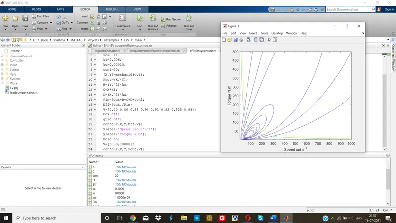
For different values of efficiency, speed – torque caharacteristics are obtained as below:
https://drive.google.com/file/d/1P3InT6MGsvUsyOn540mN-uOW0MiMieB3/view?usp=sharing