Project-1: Powertrain for aircraft in runways
Project-1: Powertrain for aircraft in runways
Part A:
- Search and list out the total weight of various types of aircrafts.
Ans.
Classification of aircrafts are as below:
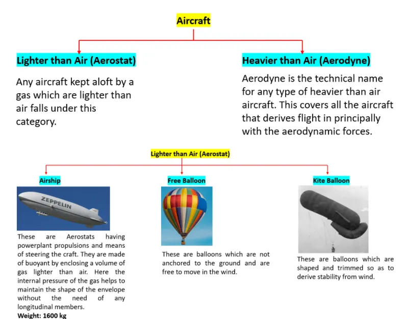
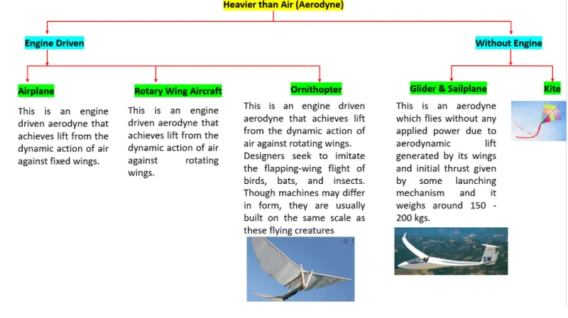
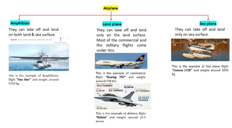
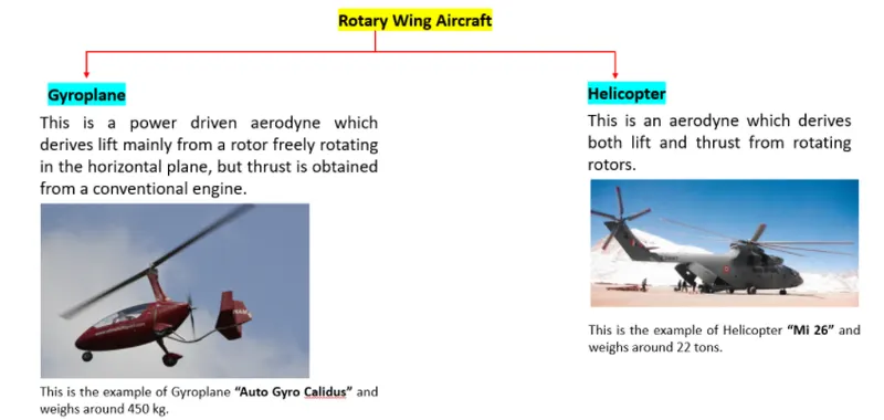
According to the purpose, principle, types of wings, material and components used, the size and weight of the aircraft varies as mentioned in above flowcharts.
2. Is there any difference between ground speed and air speed?
Ans. True airspeed is simply the speed at which an aircraft is moving relative to the air it is flying in. As such, it’s also the speed at which the air is flowing around the aircraft’s wings.
Ground speed, on the other hand, is the aircraft’s speed relative to the ground. One thing that should be noted here is that it’s its horizontal rather than vertical speed – an aircraft climbing completely vertically would have a ground speed of zero.
In other words, while airspeed is what determines whether there is enough airflow around an aircraft to make it fly, ground speed is what determines how fast an aircraft will get to its destination.
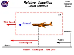
Airspeed = Ground Speed - Wind Speed
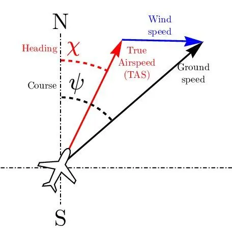
On a perfectly still day, the airspeed is equal to the ground speed. But if the wind is blowing in the same direction that the aircraft is moving, the airspeed will be less than the ground speed.
3.Why is it not recommended to use aircraft engine power to move it on the ground at Airport?
Ans. Although many aircraft are capable of moving themselves backward on the ground using reverse thrust (a procedure referred to as a power back), the resulting jet blast or prop wash might cause damage to the terminal building or equipment. Engines close to the ground may also blow sand and debris forward and then suck them into the engine, causing damage to the engine. A towing is therefore the preferred method to move the aircraft away from the gate. Unless the aircraft is in a location where it is unwise to taxi under aircraft power and necessitating a tow by a large tractor, the aircraft’s engine(s) is how the craft moves. Obviously, it is prudent to use only the amount of power to get the airplane moving and then reduce the power for taxiing to avoid high volumes of air spreading debris or damaging other aircraft or ground vehicles.
Whether jets or prop airplanes, we use the aircraft’s (engine) power to move on the airfield.
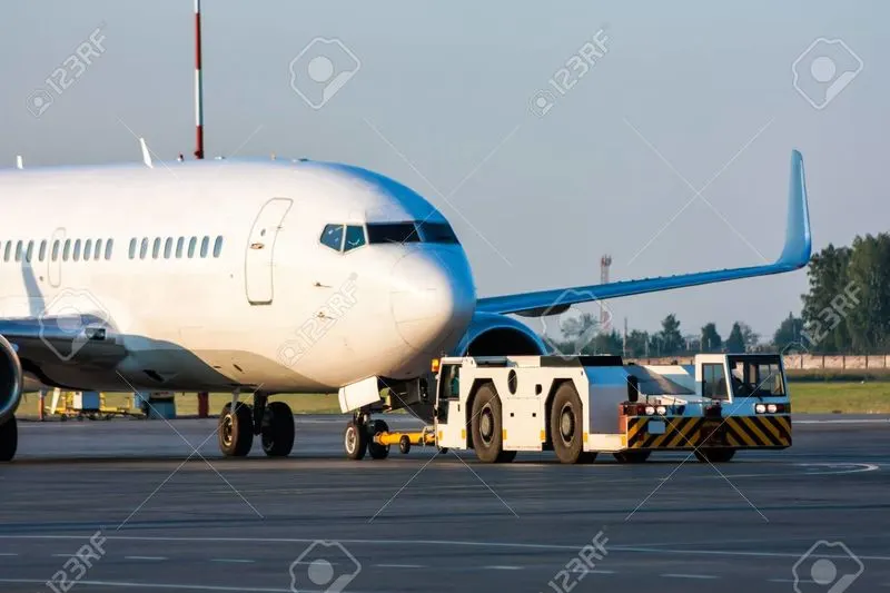
fig - Aircraft towing by a truck
Jet blast is the phenomenon of rapid air movement produced by the jet engines of aircraft, particularly on or before take-off. Jet blast can be a hazard to people or other unsecured objects behind the aircraft and is capable of flattening buildings and destroying vehicles.
Despite the power and potentially destructive nature of the jet blast, there are relatively few jet blast incidents. Due to the invisible nature of the jet blast and the aerodynamic properties of light aircraft, light aircraft moving about airports are particularly unsafe. Pilots of light aircraft frequently stay off to the side of the runway, rather than follow in the center, to negate the effect of the blast.
Towing with Taxibot saves precious fuel and reduces engine wear and tear. The ignition will be turned only when the aircraft reaches the runway. The usage of Taxibots will significantly bring down the consumption of fuel by as much as 85 percent used during taxiing of an aircraft. Taxi boats will also help in decongesting boarding gates and the apron area by providing efficient pushbacks.
So, due to the noise and fumes plus they burn a lot of fuel aircrafts are towed into a spot due to it being a small parking space for safety.
4. How an aircraft is pushed to runway when its ready to take off?
Ans.
Pushback is when an aircraft is pushed backwards away from the airport gate by vehicles called tugs or tractors.
Closer to departure, an aircraft tug will park right in front of the nose wheel.
The tug might be directly attached to the plane's nose gear with a tow bar, or could be a "wheel-lift" tug. These tugs cradle the nose gear, then lift it up before moving the plane. That gives the tug driver control over the plane's direction during pushback.
New taxi technologies are appearing, like pilot-controlled tugs, and electric motors mounted to the plane's landing gear. Both promise to save fuel, and reduce airport noise.
Takeoff is the phase of flight in which an aircraft goes through a transition from moving along the ground (taxiing) to flying in the air, usually starting on a runway. Usually the engines are run at full power during takeoff. Following the taxi motion, the aircraft stops at the starting line of the runway. Before takeoff, the engines, particularly piston engines, are routinely run up at high power to check for engine-related problems. This makes a considerable noise. When the pilot releases the brakes, the aircraft starts accelerating rapidly until the necessary speed for take-off is achieved.
The takeoff speed required varies with air density, aircraft weight, and aircraft configuration (flap and/or slat position, as applicable). Air density is affected by factors such as field elevation and air temperature.
Operations with transport category aircraft employ the concept of the takeoff V-Speeds, V1 and V2. These speeds are determined not only by the above factors affecting takeoff performance, but also by the length and slope of the runway. Below V1, in case of critical failures, the takeoff should be aborted; above V1 the pilot continues the takeoff and returns for landing. After the co-pilot calls V1, Then, V2 (the safe takeoff speed) is called. This speed must be maintained after an engine failure to meet performance targets for rate of climb and angle of climb.
The speeds needed for takeoff are relative to the motion of the air (indicated airspeed). A head wind will reduce the ground speed needed for takeoff, as there is a greater flow of air over the wings. This is why the aircrafts always take off against the wind. Side wind is not preferred as it would disturb the stability of the aircraft. Typical takeoff air speeds for jetliners are in the 130–155 knot range (150–180 mph, 240–285 km/h). For a given aircraft, the takeoff speed is usually directly proportional to the aircraft weight; the heavier the weight, the greater the speed needed. Some aircraft have difficulty generating enough lift at the low speeds encountered during takeoff. These are therefore fitted with high-lift devices, often including slats and usually flaps, which increase the camber of the wing, making it more effective at low speed, thus creating more lift. These have to be deployed from the wing before performing any maneuver.
At the beginning of the climb phase, the wheels are retracted into the aircraft and the undercarriage doors are closed. This operation is audible by the passengers as a noise coming from below the floor.
5. Learn about take off power, tyre design, rolling resistance, tyre pressure, brake forces when landing.
Ans.
TAKEOFF POWER:
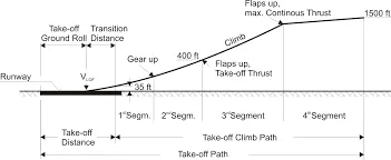
An airplane is motionless at the end of a runway. This is denoted by location O. The pilot releases the brakes and pushes the throttle to maximum takeoff power, and the airplane accelerates down the runway. At some distance from its starting point, the airplane lifts into the air. The distance the airplane cover along the runway before it lifts into the air is called the ground roll (sg). The total takeoff distance also includes the extra distance covered over the ground after the airplane is airborne but before it clears an obstacle of 50 ft for military aircraft and 35 ft for commercial aircraft. This is denoted by sa. The sum of sg and sa is the total takeoff distance.
ROLLING RESISTANCE:
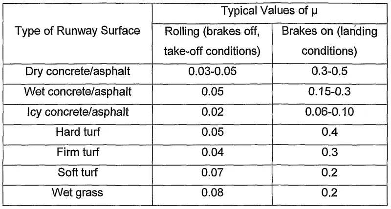
Rolling resistance R, caused by friction between the tires and the ground.
TYRE DESIGN:
The tire manufacturer with the size and weight requirements, the tire manufacturer begins the process of designing a tire that meets the needs of the aircraft manufacturer as well as all regulatory requirements — including foreign regulations in many cases.
Engineers are challenged with designing tires with cool running, heat-resistant materials while simultaneously exceeding tire service requirements. Tire prototypes are put through rigorous tests that simulate cycles of landings, take-offs, and taxi operations. It is only after the tires pass all mandatory tests and meet the requirements of the aircraft manufacturer and airworthiness authorities that the tires are put into production.
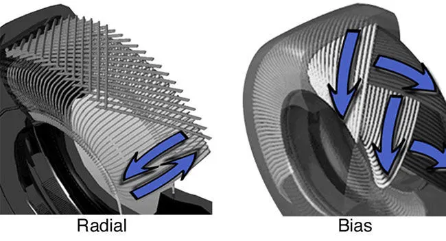
Two types of tires are used in aircraft applications — bias-ply tires and radial tires.
Bias-ply tire construction:
The tire construction consists of the following components:
Tread: The tread is made of rubber mixed with other additives to obtain the desired level of toughness, durability, and resistance to wear. The tread pattern is designed to aircraft operational requirements, with the ribbed tread design used widely due to its good traction under varying runway conditions.
Sidewall: The sidewall is a protective layer of rubber that covers the outer casing ply. It extends from the tread edge to the bead area.
Tread Reinforcing Ply: One or more layers of fabric that strengthens and stabilizes the tread area for high-speed operation.
Buff Line Cushion: The buff line cushion is made of rubber compound to enhance the adhesion between the tread reinforcing ply and the breakers or casing plies.
Breakers: Breakers are reinforcing plies of rubber-coated fabric placed under the buff line cushion to protect casing plies and strengthen and stabilize the tread area.
Casing Plies: Alternate layers of rubber-coated fabric (running at opposite angles to one another) provide the strength of the tire.
Wire Beads: Hoops of high tensile strength steel wire that anchor the casing plies and provide a firm mounting surface on the wheel. The outer edge of the bead that fits against the wheel flange is called the bead heel. The inner bead edge is called the bead toe.
Apex Strip: A wedge of rubber affixed to the top of the bead bundle.
Flippers: Layers of rubberized fabric that help anchor the bead wires to the casing and improve the durability of the tire.
Ply Turnups: The casing plies are anchored by wrapping them around the wire beads, thus forming the ply turnups.
Chafer: A protective layer of rubber and/or fabric located between the casing plies and wheel to minimize chafing.
Liner: In tubeless tires, the liner is a layer of low permeability rubber that acts as a built-in tube and restricts gas from diffusing into the casing plies. In tube-type tires, a thinner liner is used to prevent tube chafing against the inside ply.
Radial-ply tire construction
With their rigid belt, they provide increased landings and reduced rolling resistance. They have fewer components in their construction and are lighter than similarly sized bias ply tires. Components that differ from bias-ply construction as follows:
Overlay: A layer of reinforcing rubber coated fabric placed on top of the belts to aid in high speed operation.
Belt Plies: A composite structure that stiffens the tread area for increased landings. The belt plies increase the tire strength in the tread area.
Casing Plies: As in bias-ply tires, the casing plies are layers of rubber-coated fabric. However, unlike those in bias plies that run at opposite angles to one another, radial plies run radially from bead to bead.
Chippers: The chippers are layers of rubber-coated fabric applied at diagonal angles that improve the durability of the tire in the bead area.
TYRE PRESSURE:
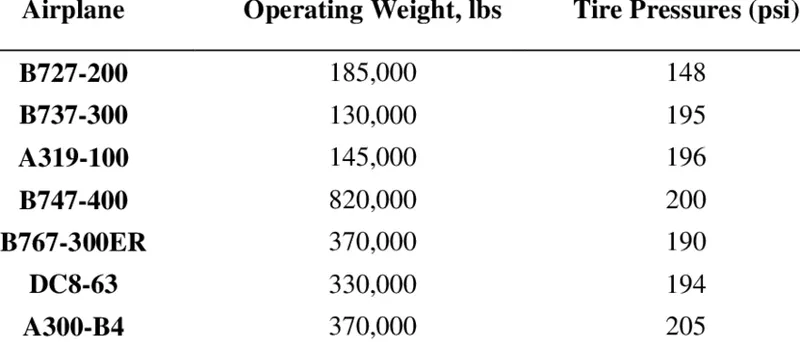
Aircraft tires generally operate at high pressures, up to 200 psi (14 bar; 1,400 kPa) for airliners, and even higher for business jets. Each of the twelve Boeing main tires is inflated to 220 psi (15 bar; 1,500 kPa), weighs 120 kg (260 lb), has a diameter of 134 cm (53 in).
BRAKE FORCES WHILE LANDING:
aircraft are equipped with an autobrake system that controls the deceleration of the aircraft by automatically optimizing the application of brake force independent of pilot operation of the brake pedals to minimize stopping distance, reduce pilot workload and smooth braking action. Another common feature of aircraft brake systems is a skid control function. Similar to anti-lock brakes on an automobile, skid control systems prevent wheel lockup. They minimize stopping distance and prevent the negative effects of skidding on tires such as unnecessary tire wear and blowout. Skid control is accomplished by applying an optimal brake force that maximizes the coefficient of friction and remains just below the amount of force that would cause skidding. In one implementation, the proper force is arrived at by continuously sensing wheel speed and comparing it to a calculated aircraft velocity. The difference between the two values represents wheel slip and brake force is reduced if it rises above a specified value.
Part B:
- A. With necessary assumptions,calculate the force and power required to push/pull an aircraft by a towing vehicle. B.Develop the model for the calculated force and power using Simulink.
Ans.
A.
Assumptions:
- Kerb weight of aircraft=60000Kg
- Payload=10000 Kg
- Towing vehicle weight=8000Kg
- Rolling friction coefficient for dry concrete= 0.03
- Acceleration due to gravity=9.81m/s^2
- Frontal area of aircraft=20m^2
- Velocity of towing vehicle=20 km/h
- Coefficient of drag for aircraft=0.19
- Coefficient of drag for towing vehicle=0.6
- Density of air=1.225 kg/m^3
For above mentioned parameters, the force required is calculated as 23.254kN and power required is 129.189kW.

B. SIMULINK MODEL for force and power calculation is:
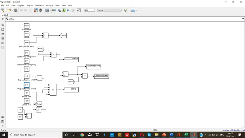
- Assumed parameters are given to the model using Constant blocks.
- Using add and multiply blocks, the formulae for rolling resistance force and Aerodynamic drag are calculated.
- Using Add block, the overall force is determined.
- By mulitplying force with velocity, power is calculated.
- The values of force and power are displayed using Display block.
We obtain the same results in Excel and in MATLAB/SIMULINK.
https://drive.google.com/file/d/12tDGi_qpLkBb-KvBEUr1WhLvGVX3n07p/view?usp=sharing
- A. Design an electric powertrain with type of motor, it’s power rating, and energy requirement to fulfill aircraft towing application in Simulink. Estimate the duty cycle range to control the aircraft speed from zero to highest. Make all required assumptions. Prepare a table of assumed parameters. Draw a block diagram of powertrain.
(Hint :DC7 Block)
B. Also, Design the parameters in excel sheet.
Ans.
BLOCK DIAGRAM FOR POWER TRAIN:
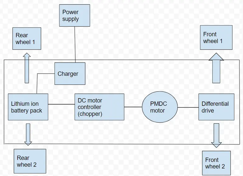
SIMULINK DIAGRAM FOR POWER TRAIN:
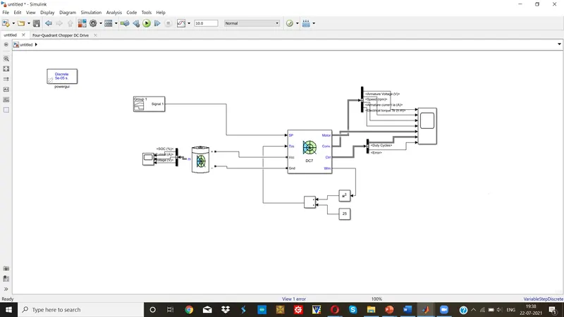
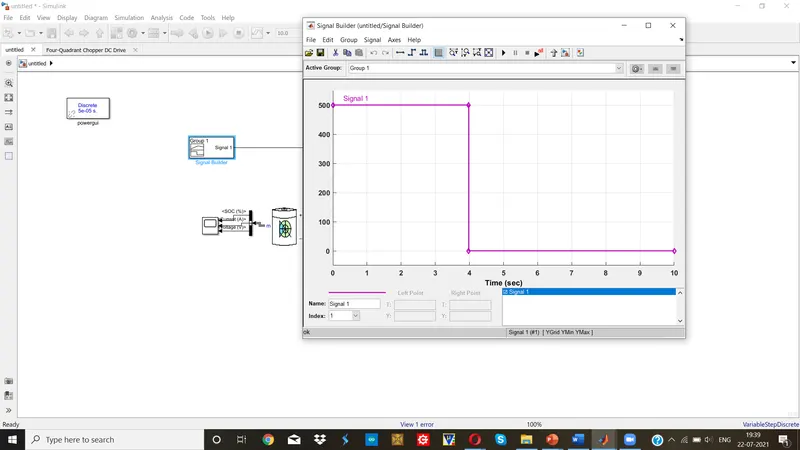
Input: Signal builder
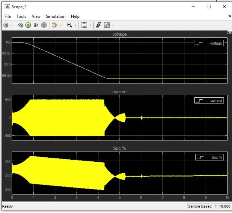
The output waveforms are:
Assumed parameters:
|
Force required to push/pull |
23.254kN |
|
Power required |
129.189kW |
|
Radiurs of tyre |
25inch =0.635m |
|
Gear ratio |
8 |
|
Transmission efficiency |
87% |
|
Motor efficiency |
95% |
|
Time taken by towing operation |
10 min |
Torque required for wheels= Total force*radius = 23254*0.635Nm = 14766Nm
Motor torque= Wheel torque/(gear ratio *transmission efficiency)
=14766/(8*0.87)
=2121.55Nm
Required motor torque= 2121.55/0.95
=2198.09Nm
Total power required =129.189/(0.87*0.95)
=156.31kW
Energy required= Total power *time =156.31*10/60 =26.05kWh
Let us consider rated power is 220kW
Then, duty cycle= Power required/ Rated power
= 156.31/220
=0.71
Therefore, duty cycle range is from 0% to 71%
B.
IMPLEMENTATION IN EXCEL

https://drive.google.com/file/d/1LbO5QW1UTkDEzh9CmhLT2UXZtx-1Z32a/view?usp=sharing