Week-11 Challenge: Braking
1. Calculate Braking Energy
In urban area driving, a significant amount of energy is consumed in braking. Electrification of vehicle makes it feasible to recover some amount of energy lost in braking.
The design and control objective of such hybrid braking system is to ensure sufficient braking force to quickly reduce the vehicle speed,properly distrubuting the brake force to front and rear axle,and also to recover as much braking energy as possible. So braking energy of a driving cycle is an important factor.
Braking energy can be calculated by the formula
Braking energy

where M = mass of the vehicle in kg
Vf = Final velocity of vehicle in m/s
Vi = Initial velocity of vehicle in m/s
Let M= 1000 kg
Let us consider the driving cycle as
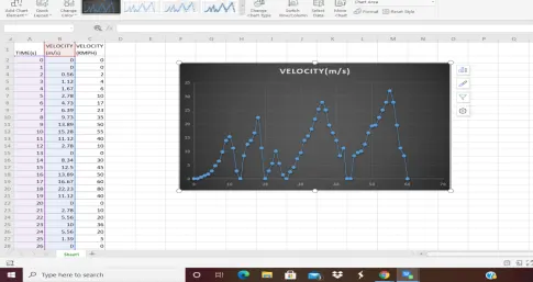
https://in.docworkspace.com/d/sIHLT3PQt_fDAhgY
the link for above sheet is provided.
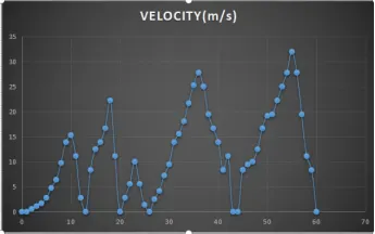
From the graph we take the instants of braking for calculating braking energy.
- First we find the instant where the vehicle is braking and accelerating

- From the braking instants we find the initial and final velocities of the vehicle during braking. Here the initial velocity of the vehicle is considered with the velocity that vehicle reached before braking is happened.
- With the required velocities the Braking Energy of each instant is found. And then the total braking energy is found.
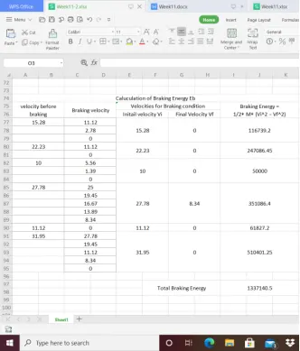
https://in.docworkspace.com/d/sIDvT3PQt3PHAhgY
We can observe that the total braking energy obtained is 1337.14 Kj for the considered driving cycle and the link for those results is provided.
2. Why electric motor can’t develop braking torque at high speed similar to starting?
The reason for electric motor not developing braking torque at high speed because
- if the drive motor is being used as generator,it is restricted by the same power limits as when it is acting as a motor because vehicles typically can brake much harder with conventional, friction-based brakes then a vehicle regenerative braking alone will have less braking capability.
- Peak torque during acceleration and deceleration are not equal.Hence electric motor can't develope braking torque at high speed similar to starting.
- It is practically not possible to recover all braking energy at high speed or high deceleration rates.
- Braking power is not only limited by the motor's power rating, but by the charging power limit of the battery pack, temperature and driving scenario.
- This makes analyzing the braking power capability difficult, as a vehicle may be able to regen-brake at full power for a short period of time but as the temperature of the battery pack rises, the braking power will quickly fall.
- A more serious issue arises when regenerative braking is applied to a two-wheel-drive brake system.
- When regenerative brakes kick in, negative torque is applied to the drive wheels, and wheels with no brakes will spin freely.
- This uneven distribution of negative torque causes uneven tire and brake wear. This could potentially cause skidding on the wheels with brakes.
- At low speed (lower than its base speed), the maximum torque is constant. At high speed (higher than its base speed), the maximum torque decreases hyperbolically with its speed hence electric motor can't develope braking torque at high speed similar to starting.
How electric and mechanical brakes are coordinated ??
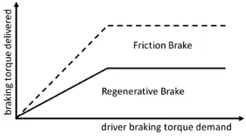
Regenerative braking in EVs and HEVs becomes complex to the braking system design. The traction motor must be controlled to produce the proper amount of braking force for recovering the kinetic energy as much as possible and, at the same time, the mechanical brake must be controlled to meet the braking force command from the driver.
There are different brake control arrangements
- Series braking
- Parallel braking.
Series Regenerative Braking
- During series regenerative braking both the electric motor and mechanical braking system work one after other.
- At first the electric motor is solely used for braking andwhen the motor or energy storage system can no longer accept more energy that the mechanical brakes are used .
- In this mechanical braking torque iscontrolled independently of the brake pedal force and has the advantage of being the most efficient by converting as much of the vehicle’s kinetic energy into electrical energy.
- For this method abrake-by-wire system is requried which either uses an electro-hydraulic brake (EHB) or an electro-mechanical brake (EMB) which require brake pedal simulators which can become costly.
- There are also many redundancies required with sensors, processors and wiring for safety which add to the complexity of the system.
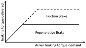
Parallel Regenerative Braking
- During parallel regenerative braking, both the electric motor and mechanical braking system always work in parallel to slow the vehicle down.
- In this mechanical braking cannot be controlled independently of the brake pedal force it is converting some of the vehicle’s kinetic energy into heat instead of electrical energy.
- This is not the most efficient regenerative braking methodbut have the advantages of being simple and cost effective.
- For this method to be used, the mechanical braking system needs little modification and the control algorithms for the electric motor can be easily implemented into the vehicle.
- This also had the advantage of always having the mechanical braking system as a back-up in case of a failure of the regenerative braking system.
3. Plot Contour of given motor Speed, Torque, Efficiency.
The losses to be considered for calculating efficiency of motor are
Copper losses
Copper loss I^2 *R
Copper loss = Kc * T^2
Where
Kc = Copper loss constant
T = torque
Iron Losses
Iron loss = Ki * ω
Where
Ki = Iron loss constant
ω = Speed
Windage Losses
Windage loss = Kw * ω^3
Where
Kw = windage loss constant
Let the motor constant values be
Kc = 0.1
Ki = 0.001
Kw = 0.0001
Constant C = 25
Matlab Script:
clear all
close all
clc

% Speed and Torque
S=linspace(0,2000,500);
T=linspace(0,1000,200);

% Motor Constants
kc=0.1; %Cu Loss constant
ki=0.001; %Iron Loss Constant
kw=0.0001; %Windage Loss constant
C=25; %Motor loss constant

[X,Y]=meshgrid(S, T); %obtaining 2-D grid for speed and torque

Pout= X.* Y; %Speed x torque = Output power
total_loss=((Y.^2)* kc)+(X.* ki)+((X.^3)*kw)+C;
Pin= Pout+ total_loss;
eff= Pout./Pin;

%efficiency levels of contouring
EL=[0.70,0.72,0.75,0.77,0.79,0.80,0.81,0.82,0.83,0.84,0.85,0.86,0.87,0.88,0.89, 0.90,0.91,0.92,0.93, 0.95];

%Plot efficiency w.r.t. speed and torque
contourf(X, Y, eff, EL)

xlabel('Speed (rpm)');
ylabel('Torque (rpm)');
title(' Efficiency Contour'); 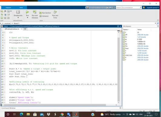
Explaination:
- First create speed and Torque array using linspace command.
- Initialize the motor loss constant values.
- Create a mesh of speed and torque using meshgrid command.
- Calculate the output power using a formula POWER = SPEED*TORQUE.
- Calculate the Total losses.
- Then calculate the efficiency using the formula efficiency = output power/input power
- Plotted the contour which represents the torque,speed along with the efficiency contour lines.
Result:
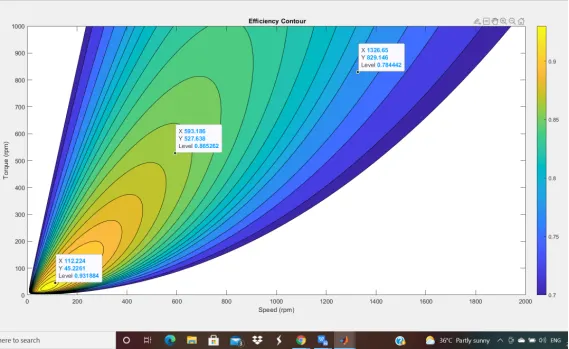
From the above plot we can observe the Speed and Torque represents along X &Y axis with efficiency contour lines.
Here we could observe the regions with different efficiency levels and operate the motor accordingly. it is observed that the inner contour lines have highest efficiency.