Week-11 Challenge: Braking
WEEK 11: BRAKING
AIM:
- For a defined driving cycle, calculate the energy required for braking.
- Why electric motor can’t develop braking torque at high speed similar to starting? How electric and mechanical brakes are coordinated?
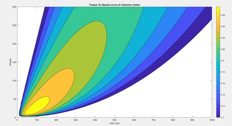
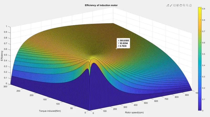
- Make a MATLAB program which plots contour of given motor speed, torque and efficiency values. Attach the code as a .m file attach a screenshot of all the plots.
STUDY 1 :>
Here we first have to make a excel sheet where we have to take various time and speed values. We have assumed the kerb weight of the vehicle 800kg and a payload weight of 200kg .
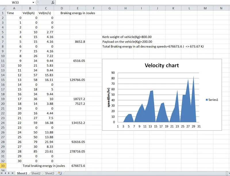
In the above drive cycle, we have taken 8 different situation of deaccelerations of which the total braking energy is calculated. The kinetic energy E of a vehicle is given by the formula E=1/2mv^2. where m is the vehicle mass and v is the speed at the start of the braking. If the vehicle decreases fro, initial speed vi to final speed vf then the braking energy is given by the formula E=1/2m(vi-vf)^2. The total braking energy calculated is 676673.6joules or 676.67KJ.
STUDY 2:>
Difference in torque values produced by an Electric motor at high speed and low speed
Electric motors have high torque producing capacities at low speeds but when the speed is raised , its torque starts to decrease, due to the increasing friction of the engines moving parts. So even if you try to rev over and above the peak torque speed ,the torque doesn't increase any further. This situation doesnt' occur in the beginning of the acceleration because most of the torque is used to increase the kinetic energy of the load and the motor.But when the speed is already high there is no extra load applied and it is not possible to develop torque.
There are two types of braking:
(i) Mechanical braking: Mechanical brakes takes all act by generating frictional forces as two surfaces rub against eachother. The stopping power of the brake depends largely on the surface of the frictional surfaces as well as the actuation force applied. They are consisted of mechanical elements for slowing or stopping of shafts in equipment drives. They use levers or linkages to transmit force from one point to another , the coupled shafts are slowed down thereafter.
Types of mechanical brakes:
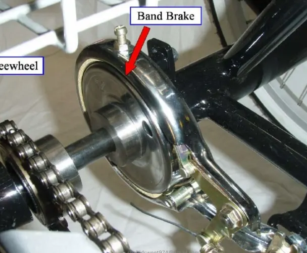
- Band brakes- These are the simplest brake configuration, it has a metal band lined with heat and water resistant friction material.
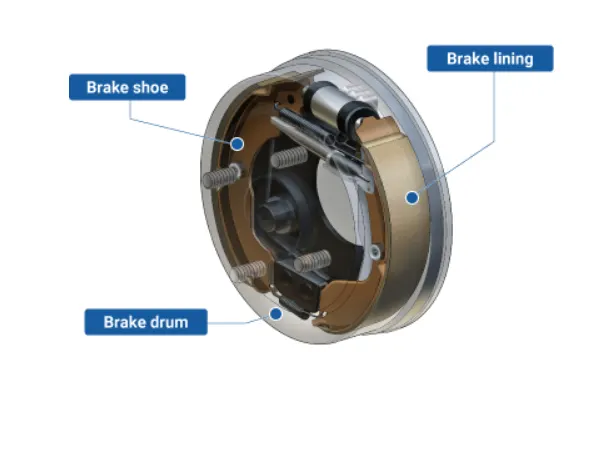
- Drum brakes- These types of brakes are used on automobile rear wheels, It works when the brake shoe is pressed against a spinning surface called drum.
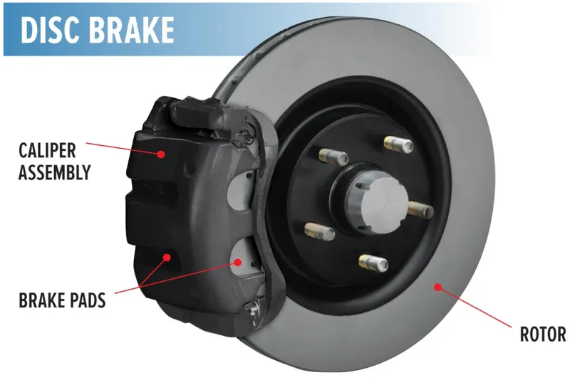
- Disc brakes- These types of brakes are constructed of brake pads, a brake calliper and a rotor. During operation, the brake pads are squeezed against the rotor.
(ii) Electrical Braking- Electric brakes are the type of brakes where we use an electric current or magnetic actuating force to slow or stop the motion of rotating component. They are used in industrial and vehicular braking applications that require fastest response time and precision tension control. Here in this braking combination The magnet in the back plate has two conductor wires which are coonected and used to tap directly into the wiring. when electricity is on, it magnetizes the brake magnet. The magnet which is associated with the drum face gets attracted to it. When it contacts this area the friction cases it to rotate, which starts moving the actuating arm, and helps is pushing the brake shoe against the drum. the brake shoe has a special type of brake pad material which resistes the heat caused by the friction. When the shoes press against the inside of the drum, they prevent the hub and the wheel that is touching the ground.
A type of electric braking is called as regenerative braking which is now commonly used in electric vehicles. Here, during the braking actionthe motor is operated as a generator. As we know that during generating action, a counter torques is produced. So this counter torque opposes the motion of the motorand motor comes to halt. Moreover the brake energy is converted to electrical energy which are fed to the source using power converters.
There are two types of Electric and mechanical brake coordination:
- Series: Herre in this case the regenerative braking and mechanical braking , Both are applied one after another.
- Parallel: Here, both the regenerative and maechanical braking are applied simultaneously.
For example, when the mechanical brake is pressed the hydraulic fluid reaches the brake pistons and creates braking pressure on the wheels and same kinetic energy is used by the regenerative braking for generating more power using the bi-directional motor which operates as a generator while braking.
STUDY 3:>
MATLAB PROGRAM FOR SPEED, TORQUE, AND EFFICIENCY CHARACTERISTICS OF INDUCTION MOTOR.
close all
clear all
clc
omega=linspace(0,1000)%rpm
T=linspace(0,300) %torque
kc=0.2
ki=0.008
kw=0.0001
[X,Y]=meshgrid(omega,T)
copper_losses=(Y.^2)*kc
iron_losses=X.*ki
windage_losses=(X.^3)*kw
con=20
op=X.*Y
input_power=(copper_losses)+(iron_losses)+(windage_losses)+(op)+con
Eff=(op)./(input_power)
n=linspace(0.7,0.95,10)
grid off
box off
contourf(X,Y,Eff,n)
colorbar
xlabel('rotor rpm')
ylabel('torque')
zlabel('Efficiency')
title('Torque Vs Speed curve of induction motor')
figure
surf(X,Y,Eff)
colorbar
xlabel('Rotor speed(rpm)')
ylabel('Torque induced(Nm)')
zlabel('Efficiency')
title('Efficiency of induction motor')
In this matlab script, we create arrays for the speed and torque for the motor using the 'linspace' command. For the speed, we consider the range of values starting from 0 to 1000 radians per second, and for the torque considering values from 0 to 300Nm. These arrays are then used to create a 2D cordinates using the 'meshgrid' command. These coordinates helps in the formation of the contour plot. we also need to consider the losses that occur in the motor's operation i.e iron-loss, copper-loss, windage-loss and conduction losses. The various losses are dependent on the speed and torque of the motor. the speed and torque are represented by omega and T. The values of coefficeents are taken as general values and conduction values are assumed to be 20 joules. Finally we plot the contour with the 'contour' command.
OUTPUT: