Electric Vehicle Braking (MATLAB)
AIM:
To understand the concepts of electric vehicle braking.
OBJECTIVE:
To answer the following questions
- For a defined driving cycle, calculate the energy required for braking.
- Why electric motor can’t develop braking torque at a high speed similar to starting? How electric and mechanical brakes are coordinated?
- Make a MATLAB program that plots the contour of given motor speed, torque and efficiency values. Attach the code as a .m file attach a screenshot of all the plots.
SOLUTIONS:
- the energy required for braking
To reduce the speed of a vehicle, some amount of energy must be spent on braking the vehicle. The amount of energy required can be calculated using the energy equation which os showed below
Energy= 0.5* mass* change in velocity(v_f - V_i).
the power required for braking is given by the equation
power = energy/ time
The Drive cycle taken into consideration is the UN/ECE drive cycle, the image of this is shown below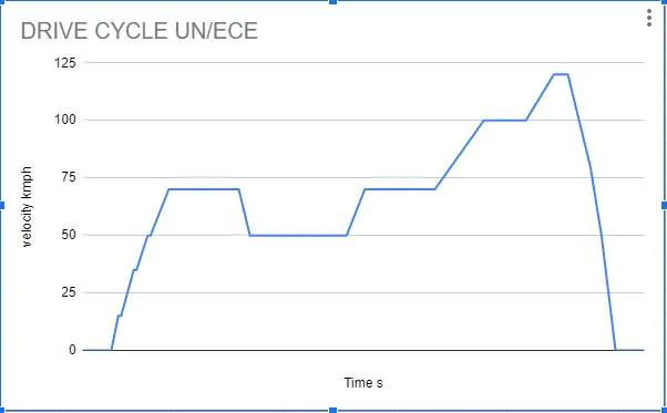
There are two major braking zones in this drive cycle, the calculation of te energy taken for the braking was calculated on excel, it is shown below.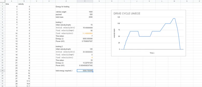
The link to the sheet is: Braking calculation - Why electric motor can’t develop braking torque at a high speed similar to starting? How electric and mechanical brakes are coordinated?
When it comes to controlling an electric machine by electric drivers braking is a very important term because it helps to decrease the speed of the motor according to will and necessity. The braking of induction motors can be classified mainly into three types
- Regenerative braking.
- Plugging or reverse voltage braking
- Dynamic braking
To explain that regeneration braking for induction motor, we can take help of the equation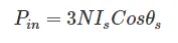
Here, θs is the phase angle between the stator voltage and stator current, the simple words whenever this phase angle exceeds 90° (i.e θs>90°) regenerative braking can take place. To explain this more clearly and easily we can say that whenever the speed of the rotor exceeds synchronous speed, regeneration braking occurs. That is because whenever the rotor rotates at a speed more than synchronous speed there is a reverse field occurs which opposes the normal rotation of the motor and therefore braking takes place. The main disadvantage of this type of braking is that the speed of the motor has to exceed synchronous speed which may not be possible every time. To acquire regenerative braking at a lower speed than synchronous speed, a variable frequency source can be used.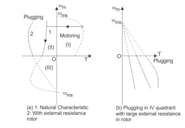
Plugging of induction motors is done by interchanging any two of the supply terminals. When the terminals are reversed the operation of the machine changes from motoring to plugging. From a technical point of view and for better understanding it can be said that the slip changes from ‘s’ to (2-s), which indicates that due to reversal of the terminals the torque also changes its direction and braking occurs.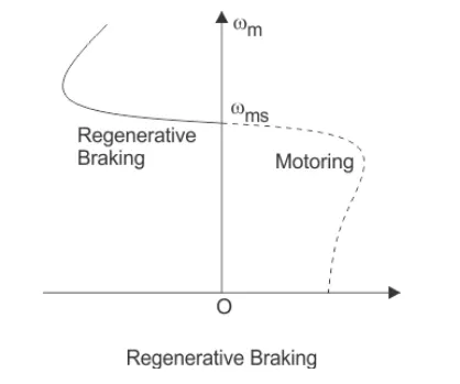
The first classification of dynamic braking of induction motors is AC dynamic braking any one of the supply phases is disconnected from the supply and then it is either kept open or connected with the other phase. The first type is known as the two lead connection and the second one is known as three lead connection. To understand this braking method clearly, we can assume the system to be a single-phase system. Now the motor can be considered to be fed by positive and negative sequence voltages. That’s why when the rotor resistance is high the net torque is negative and braking can be acquired.
Sometimes capacitors are kept permanent by connected across the supply terminals of the motor. This is called self-excited braking using capacitors of induction motors. This type of braking works mainly by the property of the capacitors to store energy. Whenever the motor is disconnected from the supply the motor starts to work as a self-excited induction generator, the power comes from the capacitors connected across the terminals. The values of the capacitor are so chosen that they are sufficient to make the motor work as an induction generator after being disconnected from the supply. When the motor works as an induction generator the produced torque opposes the normal rotation of the motor and hence braking takes place.
Another type of dynamic braking is dc dynamic braking. In this method, the stator of running induction motor drives is connected to dc supply. The consequences of connecting a dc supply to the stator are as follow, the DC current produces a stationary magnetic field, in the rotor keeps rotating and as a result, there is an induced voltage in the rotor winding, therefore the machine works as a generator which opposes the motion of the motor and braking is acquired
There are two methods to co-ordinate mechanical and electrical brakes
series - in this method first motor braking is used, followed by mechanical braking
parallel - in this method both motor braking and mechanical braking are applied simultaneously, this is controlled by a computer to ensure the best braking configuration
- MATLAB program which plots contour of given motor speed, torque and efficiency values.
The code written is shown below
close all clear all clc x= linspace(1,1000); y=linspace(1,250); % motor loss constants kc=0.2; % for copper losses ki=0.008; % for iron losses kw=0.00001; % for windage losses cl=20; % for motor loss constant % creating the mesh [X,Y] = meshgrid(x,y); outputp= (X.*Y); %power= speed* torque B= (Y.^2)*kc; % copper losses C= X*ki; % iron losses D = (X.^3)*kw; % windage losses inputp= outputp + B + C + D + cl; eff = outputp./inputp; %efficiencies for contour v=[0.7 0.8 0.85 0.9 0.91 0.92 0.93 0.94 0.95]; box off grid off contour(X,Y,eff,v); xlabel('speed rad/s'); ylabel('torque N.m'); hold on v=[8000,10000]; contour(X,Y,outputp,v);
The plot is shown below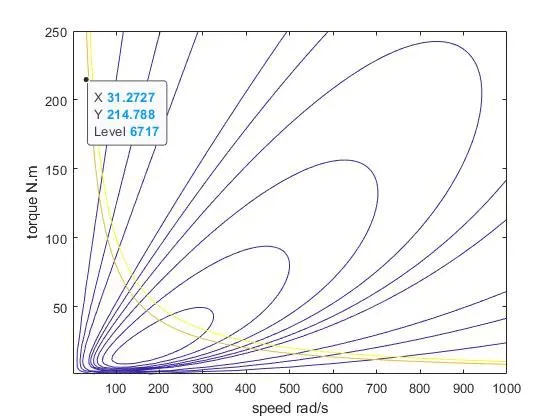
CONCLUSION:
The concepts of electric vehicle braking were understood