Week 11 Challenge
CHALLENGE 11
Aim: The main aim of this challenge is to gain the knowledge about the design of the pipe rack along with it the concept of application of the loads to the structure with the help of STAAD software. The concept of applying the load combination with the help of the software is also learnt. The procedure that is adopted to assign the member properties to the members is also learnt. And the concept of defining the design parameters that are required for the design of the pipe rack are also learnt with the use of the software.
Analysis & Design of Pipe Rack Structure in STAAD.pro
- Friction load determination
A pipe carrying LNG rests on the shoe having vertical force of 125 kN. Calculate the Friction load on the axis. Also find the friction force, if TEFLON pad is used between shoe and pipe support.
Ans:Friction factor/Coefficient and friction load on piping:
Materials Friction Factor
Steel to Steel 0.3
Teflon to Steel 0.1
(A) When Steel pipe is resting on steel:
Friction force in longitudinal direction (Ff) = Coeff of friction x Gravity Load
= 0.3 x 125 KN = 37.5 KN
Friction load in transverse direction = 10% of piping operating load
= 0.l x 125 = 12.5 KN
(B) When Steel pipe is resting on Teflon :
Friction force in longitudinal direction (Ff) = Coefficient of friction x Gravity Load
= 0.l x 125 KN = 12.5 KN
Friction load in transverse direction = 10% of piping operating load
= 0.l x 125 = 12.5 KN
- Support Types
Identify the type of support as Spring, Guyed, Stop or Semi Anchor (Guyed + Rest + Stop ) or Rigid Strut from following images.
Figure 1
Ans: Spring
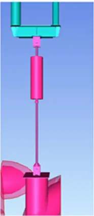
Figure 2
Ans: Rigid strut
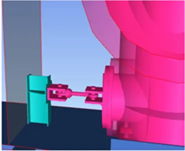
Figure 3
Ans: Stop + rest support
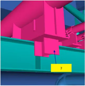
Figure 4
Ans: Guyed + Stop + Rest
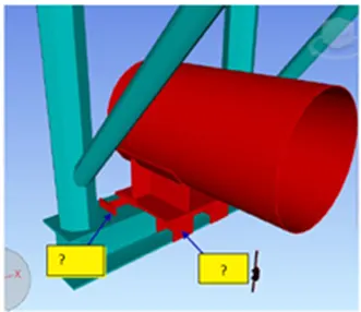
Figure 5
Ans: guyed + rest
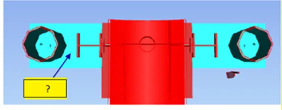
Figure 6
Ans: Guyed
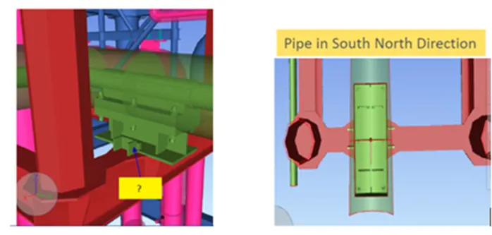
- Design of a pipe rack
Design a typical pipe rack bent in oil plant. The pipe rack configuration shall be as shown in Figure 1 and the plan layout as shown in Figure 2.
Figure 1
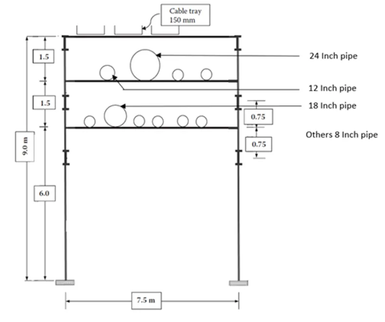
Figure 2
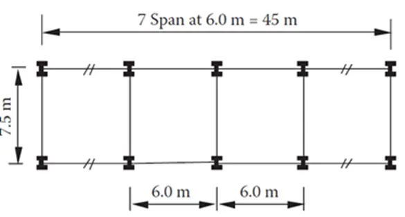
Ans: MODELLING PROCEDURE
- As soon as the STAAD software is opened the analytical model is selected and then the units that are used for load and distance measurement are selected and then the file is saved at the appropriate location.
- Next the nodes are created with the help of the structure node option that appears at the right side of the screen. In that the co-ordinates are entered in the format of X, Y, Z system. Where the X is along the horizontal direction and Y is along the vertical direction and Z is also along the horizontal direction. For example if the node as to be created at a distance of 5m in the X direction then the co-ordinated would be 5, 0, 0. The same procedure is adopted to model the entire frame. In case of repetitive distance measurement then the particular node is selected and the transitional repeat option is used to repeat the number of operation.
- Then these nodes are connected with each other with the help of the add beam option which helps to create the beams and columns and rafter. The beams are connected as per the requirement. The beams can also be repeated with the help of the transitional repeat option or with the help of the copy beam option.
- Thus the structure that is required is modelled. The extra beams that are not required are deleted.
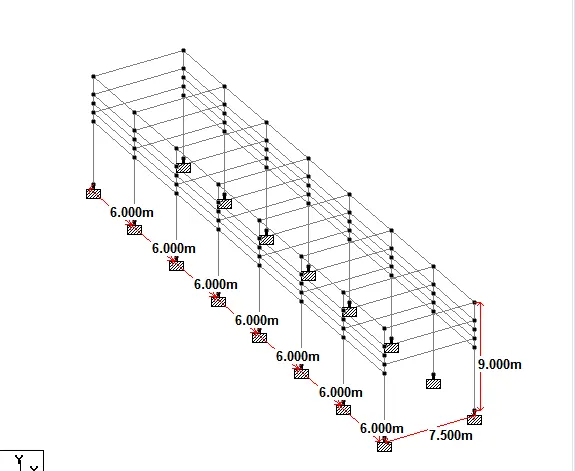
- MODEL
ASSIGINGING MEMBER PROPERTY AND SUPPORT PROCEDURE
- In order to assign the member properties to the members select the geometry command, under that select the property command. A dialogue box appears. In the dialogue box select section data base for the steel structure. Then select Indian. Under that the various sections that are available in the market are displaced.
- After selecting Indian it provides various sections for all shapes of the sections. The different shapes available in the steel sections are I sections, Angle sections, Channel sections, Tube sections etc.
- The members that are required for the structure are selected and then the add option is selected which appears at the bottom of the window.
- In the same manner all the member properties that are required from the different shapes are add to the chart.
- Then each member property is selected and it is assigned to the members as per the question given. For example ISMB500 has been asked to assign to the columns. The property ISMB500is selected first and then the columns are selected.
- After that the assign to the selected beams option is selected which appears below the dialogue box is selected. Thus the property ISMB500 is assigned to the columns.
- Then the support to the columns should be assigned. Under the geometry section Support command is selected. A dialogue box appear, in that create option as to be selected. Then the dialogue box with various support conditions appears like fixed, pinned etc. as per the requirement fixed and pinned support condition are to be selected and then the add button is clicked.
- The fixed support are assigned to the exterior columns and the pinned support are assigned to the interior columns.
DEFINING LOAD AND LOAD COMBINATION PROCEDURE
- In order to define the loads go to the loading option under geometry and select the load case option and define the loading types as dead load and live load. Name dead load types as DL and live load type as LL
- Now select DL and click on the add button to add that comes under DL. As per the given question the DL are 1.53kN/m for rafter and LL of 0.375kN/m for rafter.
- For 1.53kN/m and 0.375kN/m select the command as uniform force from the loading command and enter the value of the load with negative sign so that the load acts in the downward direction.
- Click on the load to be assigned and then select the member for which the particular load as to be assigned and the select the assign to the selected beams or nodes.
- In order to define the load combination select the command option and under command option select loading, under loading there is a option called load combination select that. Then the dialogue box appears with the load that we have defined. Select DL and LL and give the factor as 1.5 for both DL and LL. Save the combination with appropriate name.
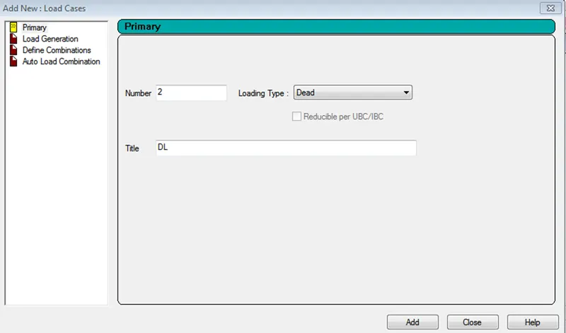
- DEFINING DEAD LOAD (DL)
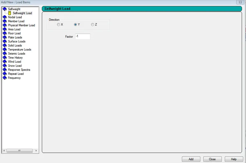
- DEFINING SELF WEIGHT
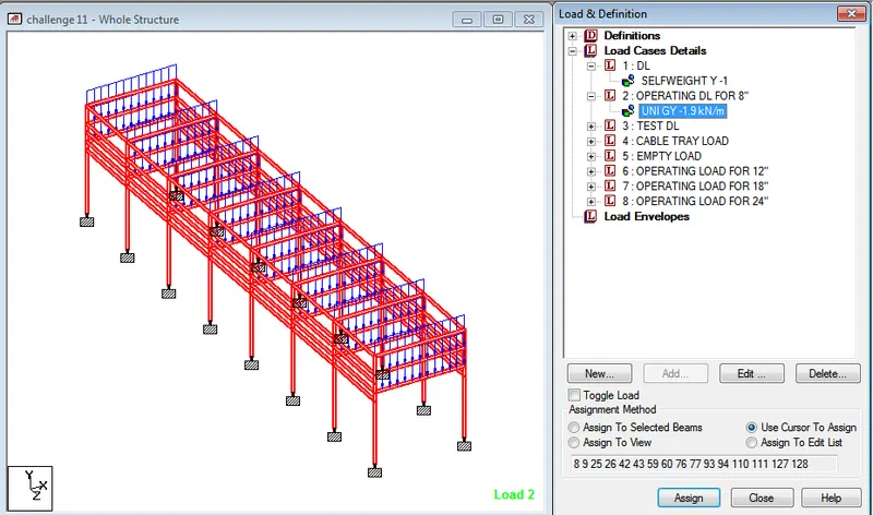
- OPERATING DEAD LOAD FOR 8" DIA PIPE
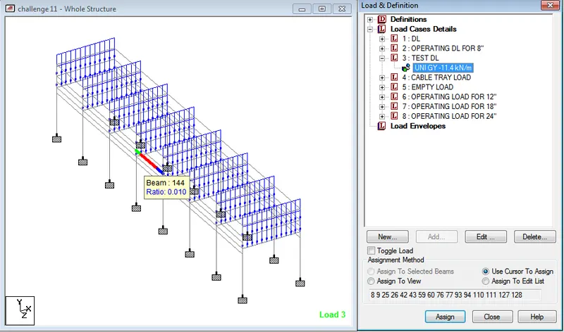
- TEST LOAD
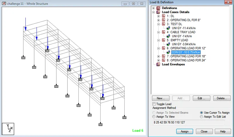
- OPERATING DEAD LOAD FOR 12" DIA PIPE
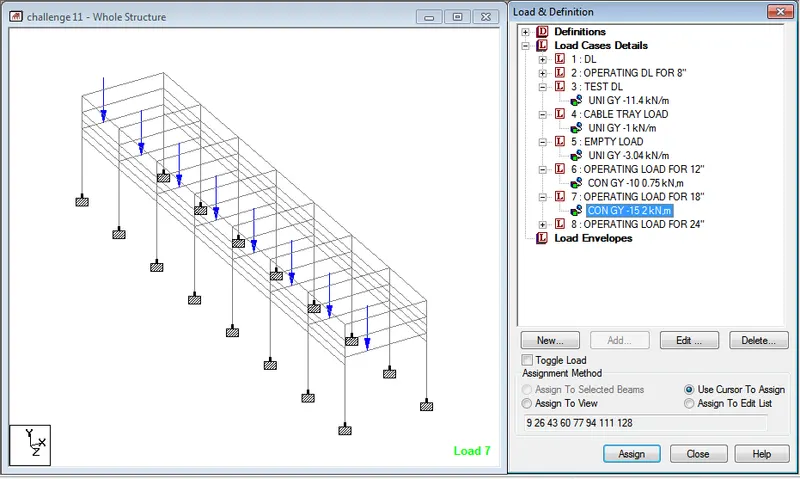
- OPERATING DEAD LOAD FOR 18" DIA PIPE
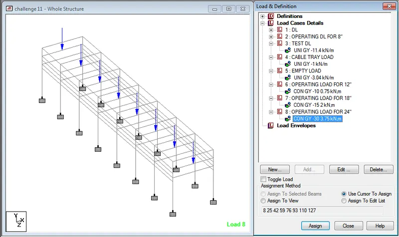
- OPERATING DEAD LOAD FOR 24" DIA PIPE
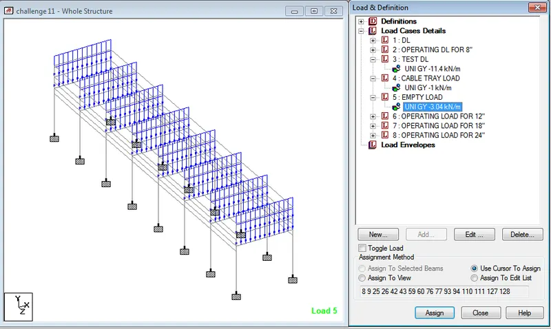
- EMPTY LOAD
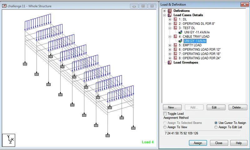
- CABLE TRAY LOAD
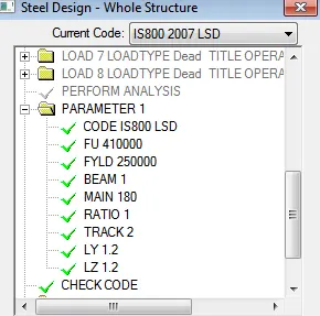
- DESIGN PARAMETERS
Conclusion:
From the project carried out it can be concluded that the concept of the modelling of a pipe rack structure and the application of the loads and defining of the load combination to the structure as per the given data with the use of the STAAD software is learnt. The procedure that is followed while assigning the loads to a structure is known. The method that as to be adopted for fixing up the errors and the warning are also learnt.
Vijayalakshmi S H