Week 11 Car Crash simulation
CAR CRASH SIMULATION USING ANSYS WORKBENCH
AIM:
To study and perform explicit dynamic analysis for car crash simulation. There will be three different analyses on the same model with varying types of thickness and get results for Equivalent stress and the total deformation in the model and grid dependency test was also performed to optimize the element size for better accuracy.
Case 1: Thickness 0.3 mm for Car Body
Case 2: Thickness 0.5 mm for Car Body
Case 2: Thickness 0.8 mm for Car Body
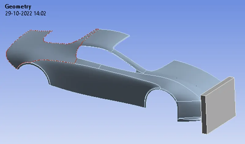
GEOMETRY
MATERIALS:
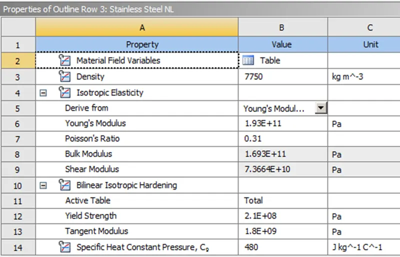
Below are the materials which are used to perform analysis for the dynamic analysis of the model. The analysis is carried out for the given material individually.
Car Body: Stainless Steel NL
Wall: Structural Steel
The details of each material have been carried out below as shown in the image:
CONNECTION DETAILS:
Body interactions:
In this type, all bodies are selected as its interaction part as its geometric selection part. As its definition type is frictionless.
Symmetry:
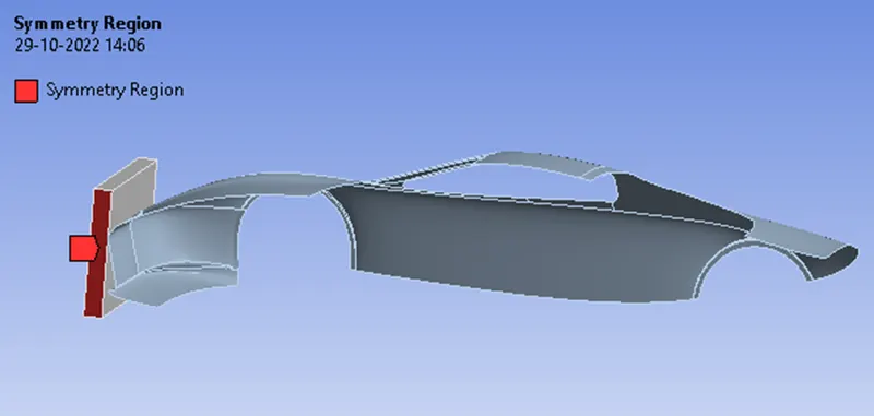
As we have selected 1 face of the wall as its geometric selection and it's symmetric to the X-axis of the global coordinate system.
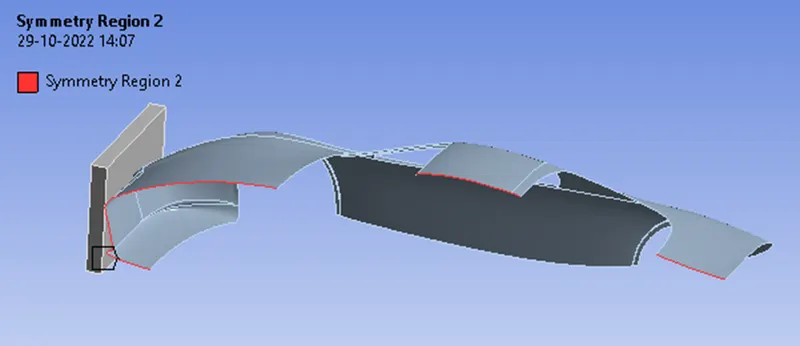
For the same, we have selected 7 edges for the car body as its geometric selection part and it's symmetric to the X-axis of the global coordinate system.
MESH:
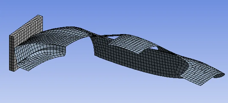
Basically, we have preferred default mesh for the whole setup
ANALYSIS SETTINGS AND BOUNDARY CONDITIONS
ANALYSIS SETTINGS:
For this analysis the number of steps is set to 1 with a maximum number of cycles is 1e+07 and the end time as 1e-3 and it is defined by time, hence initial, maximum, and minimum time will be program-controlled. As the maximum energy error would be 5.
BOUNDARY CONDITIONS:
Fixed Support:
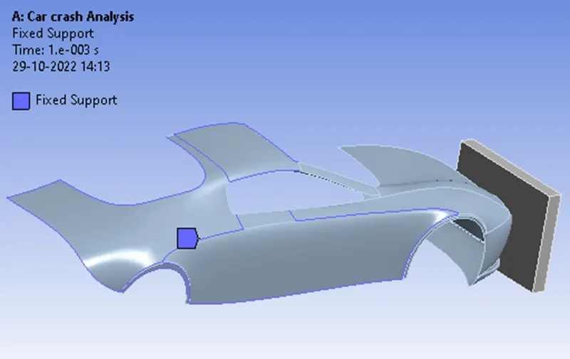
Basically, we have to fix the part so as to analyze the results. Therefore, we have fixed the 16 edges of the car body as its geometric selection and we have selected it as fixed-type support.
Displacement:
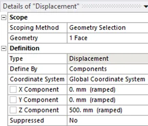
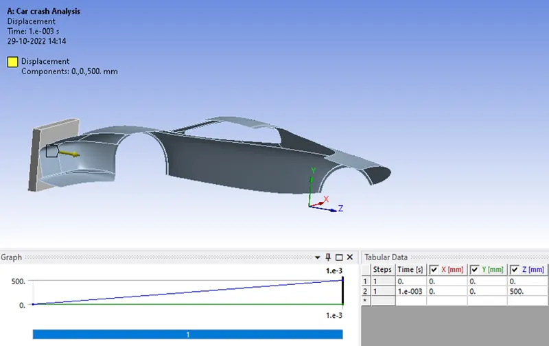
As we have to select the 1 face of the wall as its geometric selection part. Then its type is specified by displacement and its coordinate system is defined by 'Global coordinate system'. Then, its Y and Z component gets a value as constant and the Z component value gets linear direction displacement in tabular form.
POST-PROCESSING RESULTS:
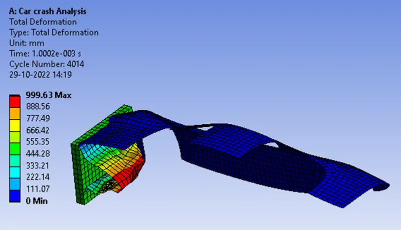
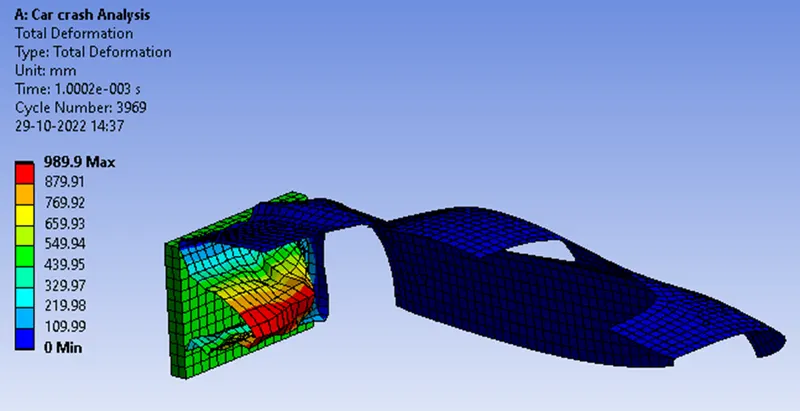
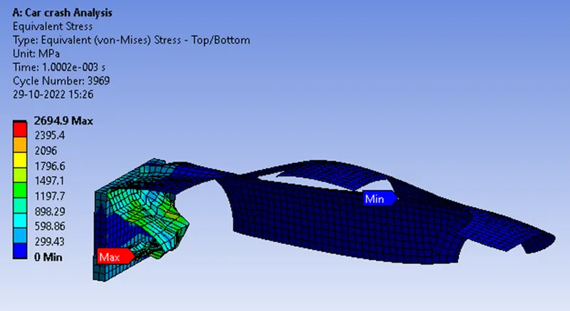
Now, we have to compare the deformation and stress on the basis of different materials. Then, we have to analyze the result for total deformation, and equivalent stress for dynamic analysis for operation. The results are as shown below:
Case 1_Thickness 0.3 mm:
Total Deformation:
Equivalent Stress
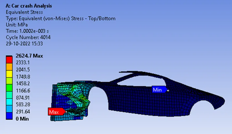
Here maximum stress is 2624.7 MPa.
Due to the collision of the Car Body with the wall, we can see the maximum stress is occurring at the wall.
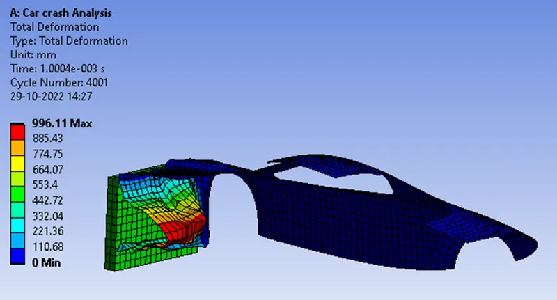
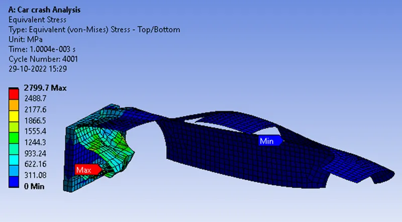
Case 2_Thickness 0.5 mm:
Total Deformation:
Equivalent Stress:
Case 3_Thickness 0.8 mm:
Total Deformation:
Equivalent Stress:
CONCLUSION:
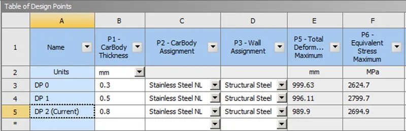
From the above results, we can conclude that the stress and deformation are decreasing and increasing in the thickness of the Car Body.
With 0.3 mm thickness, the car body will be very light in weight and can accelerate high, so all the energy will be dissipated to the Car body and the damage will also be high.
With 0.5 mm thickness, it will be a little rigid. So, it will not dissipate more energy and the energy will be transferred to the whole car body, which is also not good.
With a thickness of 0.8 mm, the car body will not be so rigid and also not accelerate more, so energy absorption will be optimized.
So, 0.8 mm thickness is preferred for the car body for good crash safety results.