Week 11- Assembly Workbench
ASSEMBLY WORKBENCH
OBJECTIVE:
To create individual 3d parts from the input given and then create an assembly out of it.
REQUIREMENT:
- To design 3d parts
- Create a assembly (Quick Return Mechanism & CV joint)
- To create 2d drawing for the assembly as well as the individual parts
INPUT:
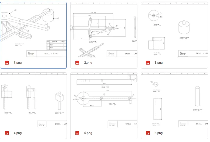
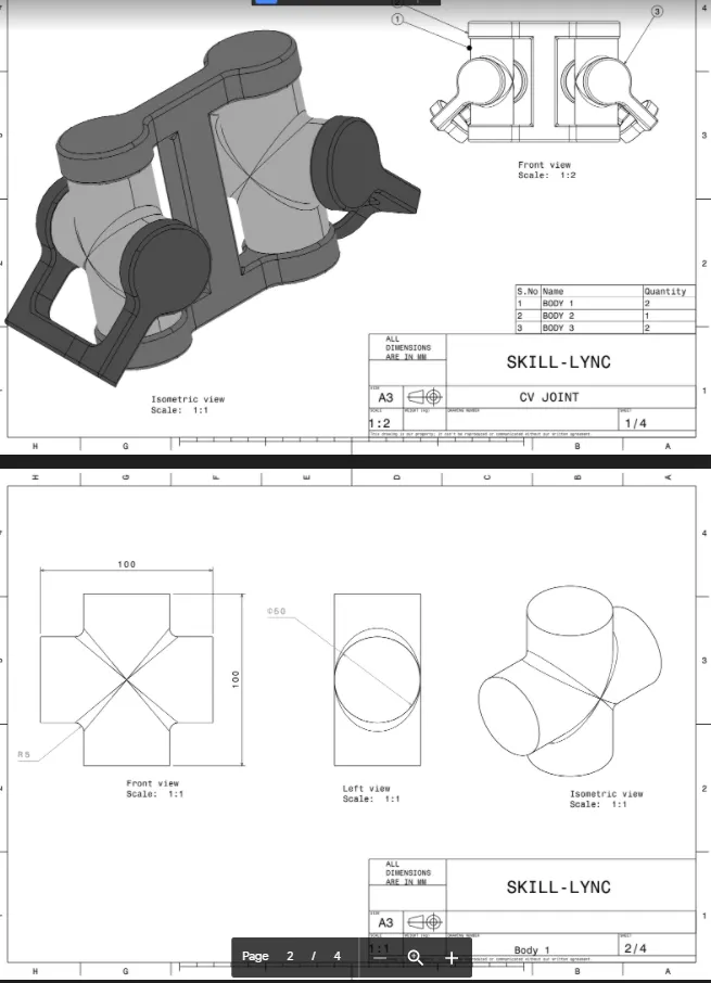
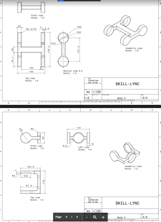
PROCEDURE:
Using part workbench individual parts of Quick return mechanism is designed following the inputs.
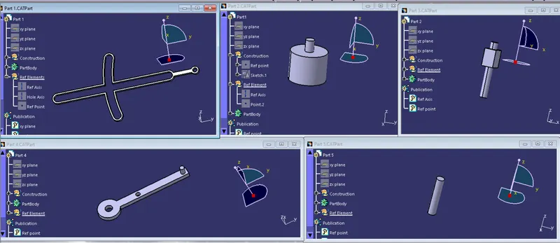
Using same part workbench individual parts of CV joint is designed following the input given.
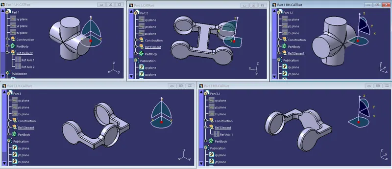
All the sketches used to create the 3d parts are iso constrained.
ASSEMBLY WORKBENCH:
QUICK RETURN MECHANISM ASSEMBLY:
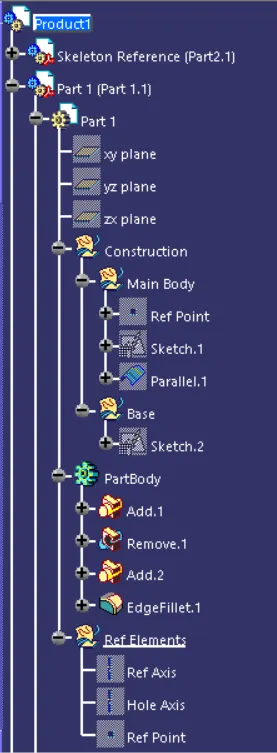
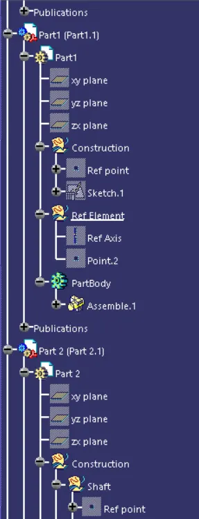
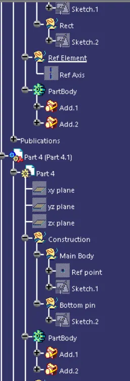
An assembly workbench is created and all the related parts of the Quick return mechanism are inserted into the product file using existing component tool.
A base reference is created and that is named as skeleton reference.

Initially a particular component of a assembly is fixed with the skeleton reference.
Using the plane and the ref point the part is coincided to the skeleton reference where it can't be moved.
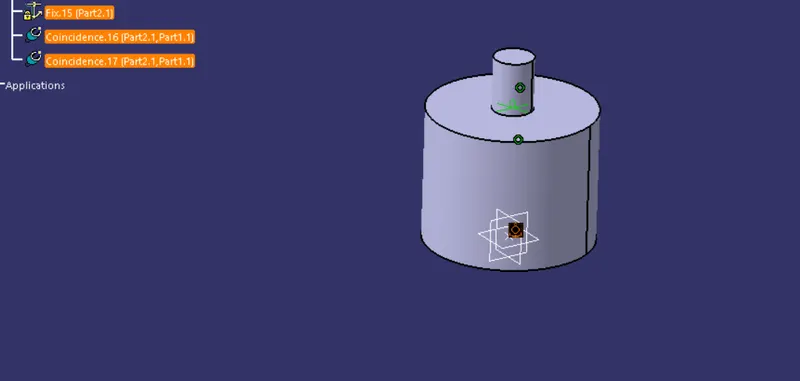
Keeping this component as a base all the other parts are going to get assembled to it.
Using the axis and the faces of the respective parts,the main body is attached.
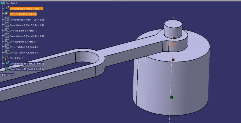
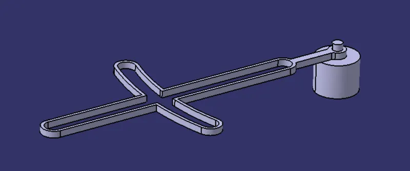
The axis of the shaft and the main body is coincided.
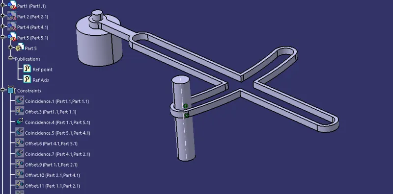
Using the same coincidence tool the axis of the parts are coincided and using distance tool parts are mated together.
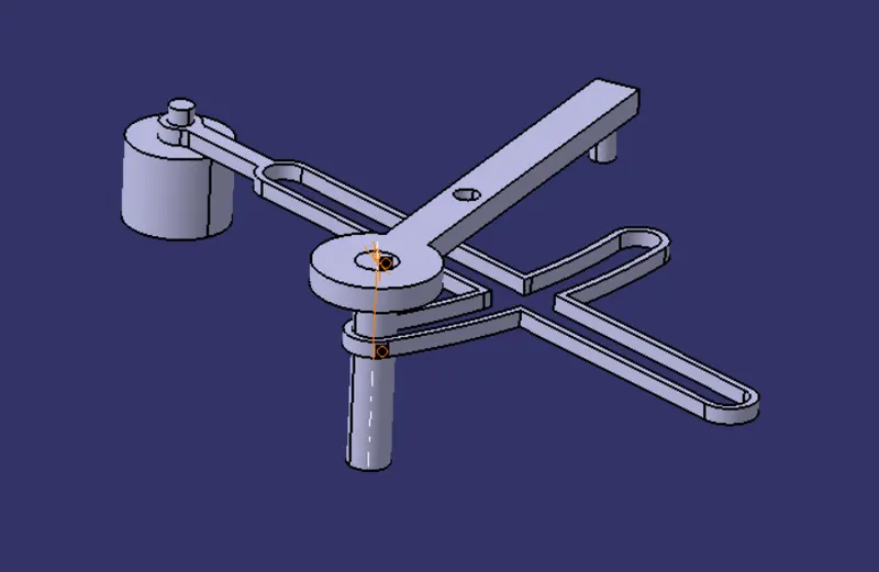
The last part of the Quick return mechanism is assembled to the main body using the coincidence and the distance tool.
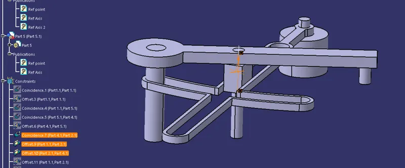
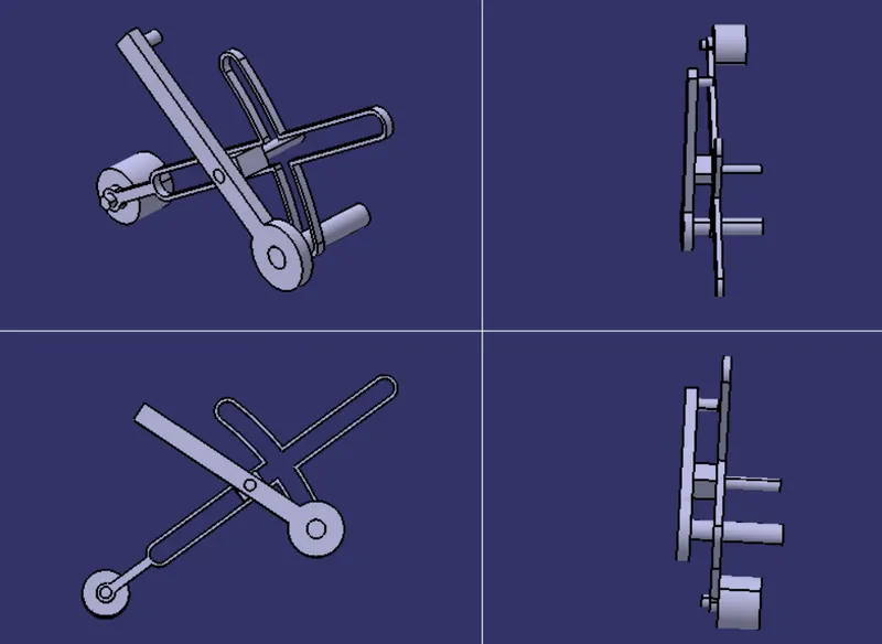
FINAL OUTPUT:
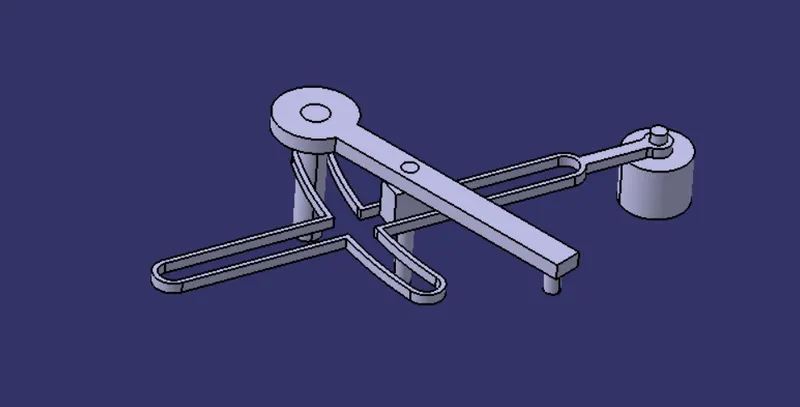
VARIOUS ORIENTATIONS:
TREE STRUCTURE:
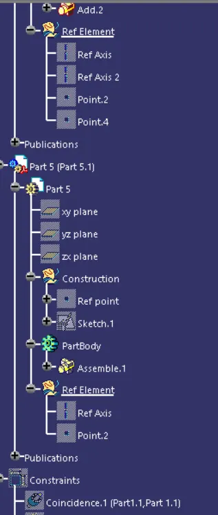
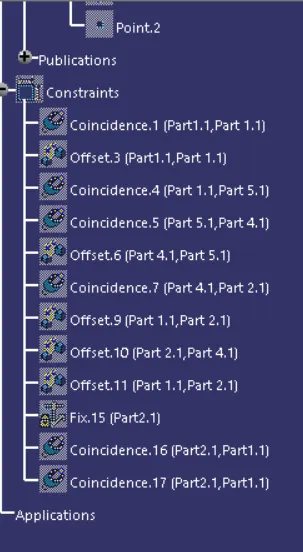
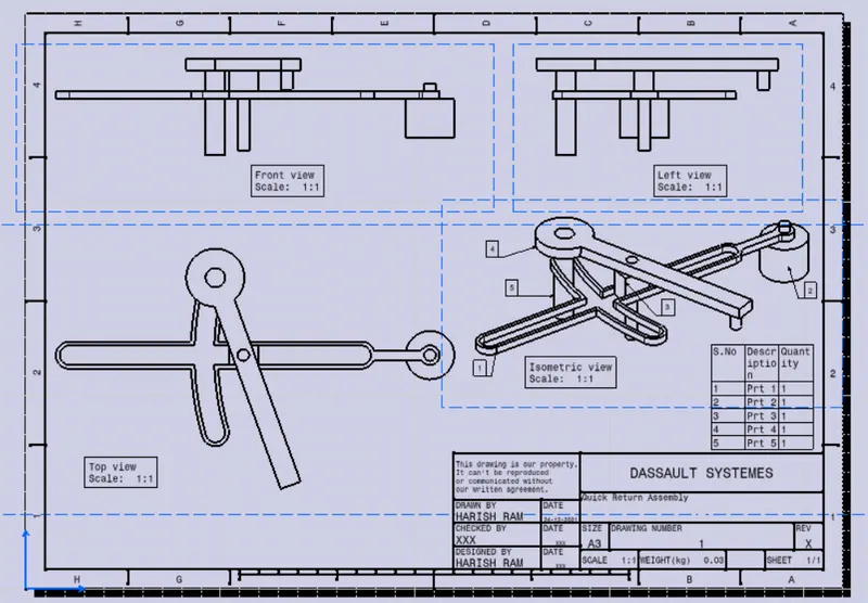
DRAWING FOR THE QUICK RETURN MECHANISM ASSEMBLY:
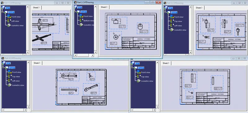
DRAWINGS FOR INDIVIDUAL PARTS OF THE QUICK RETURN MECHANISM ASSEMBLY:
CV JOINT ASSEMBLY:
An assembly workbench is created and all the related parts of the CV joint are inserted into the product file using existing component tool.
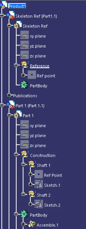
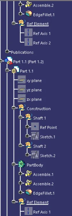
A base reference is created and that is named as skeleton reference.
Initially a particular component of a assembly is fixed with the skeleton reference.
Using the plane and the ref point, the part is coincided to the skeleton reference where it can't be moved.
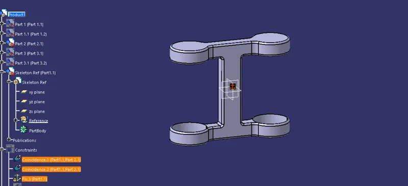
Keeping this component as a base all the other parts are going to get assembled to it.
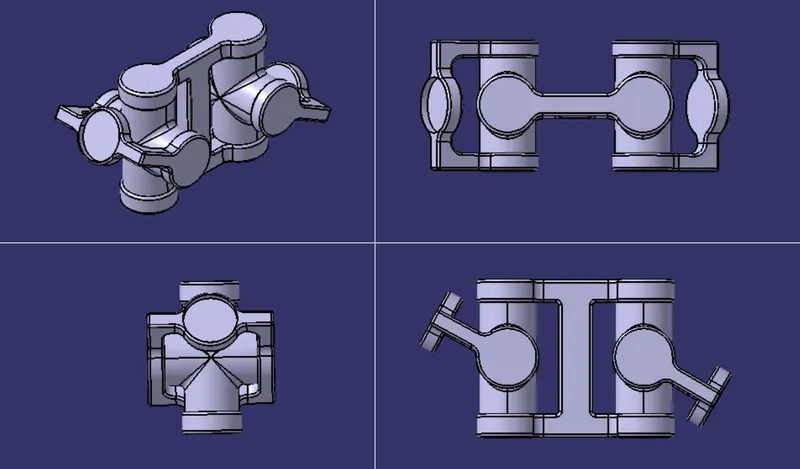
Here LH and RH child parts are assembled together and later it will be aseembled to the main body.
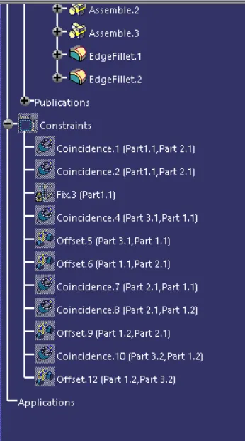
Here coincide and distance tool is uded to mate the parts.
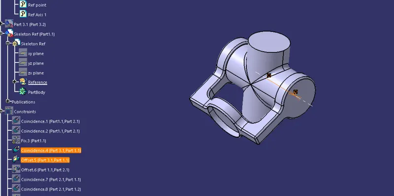
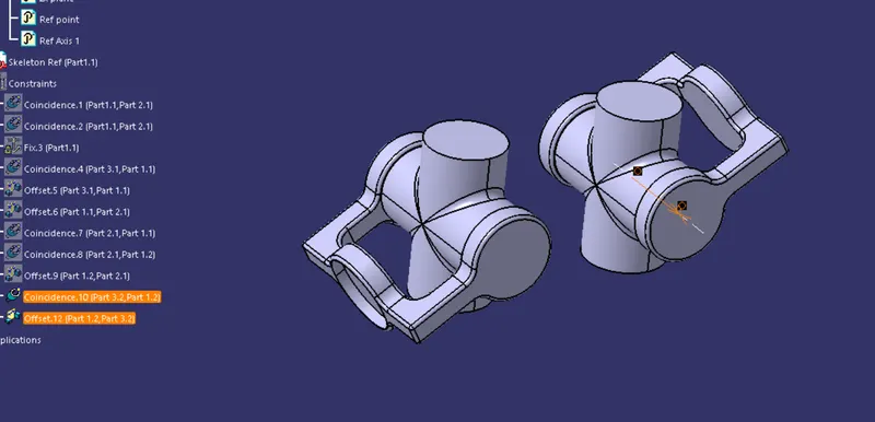
Later the assembled parts are mated to the base body using teh same axis coincidence and distance tool to get a desired assembly of CV joint.
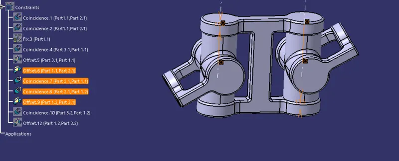
FINAL OUTPUT:
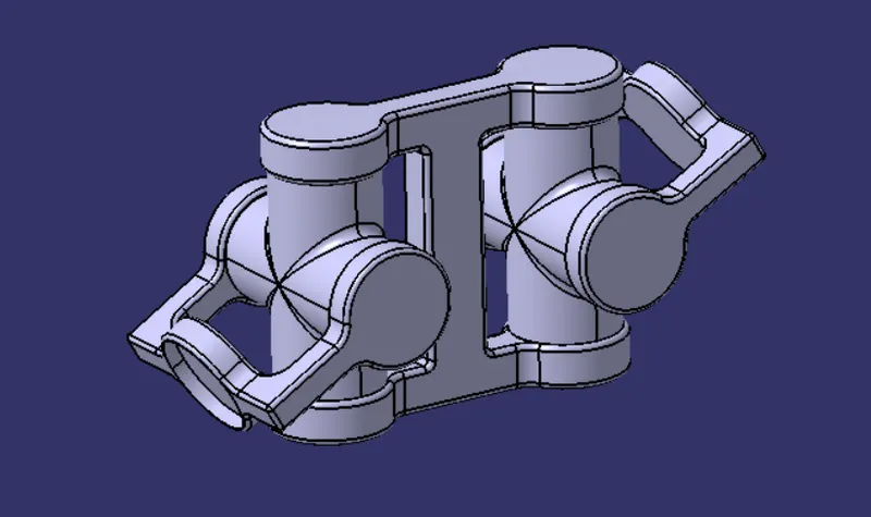
VARIOUS ORIENTATIONS:
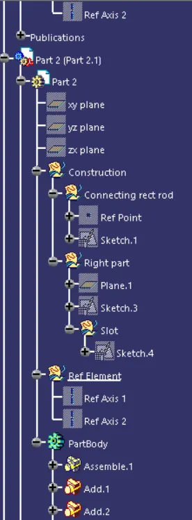
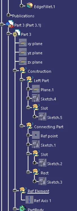
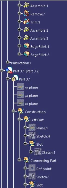
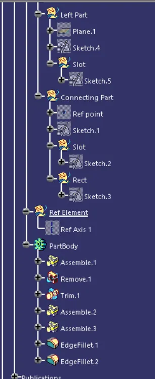
TREE STRUCTURE:
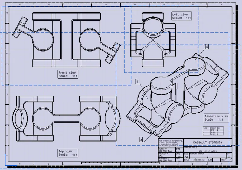
DRAWING FOR THE CV JOINT ASSEMBLY:
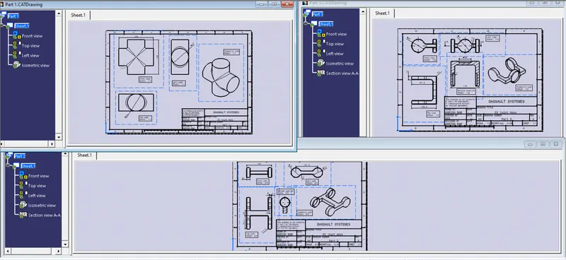
DRAWINGS FOR INDIVIDUAL PARTS OF THE QUICK RETURN MECHANISM ASSEMBLY:
CONCLUSION:
To conclude the 3d parts are designed and the assembly of Quick return mechanism and CV joint is created as a product file and drawing files are also created for the assembly as well as for the individual parts.
Software used:CATIA.