Week 11- Assembly Workbench
Objective:
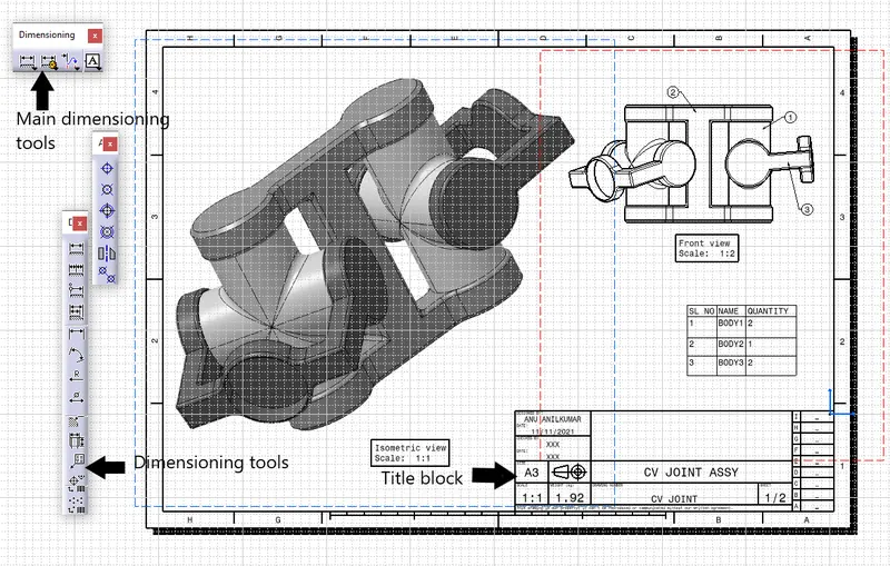
Create the 2 assemblies as per given diagrams and create drawing sheets for each of them .
Answer:
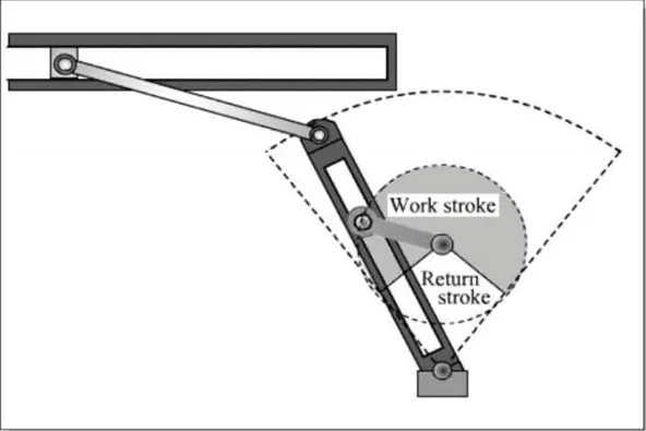
Assembly1 : Quick return mechanism
Assembly2: CV Joint
Introduction:
Quick return mechanism : A quick return mechanism is an apparatus to produce a reciprocating motion in which the time taken for travel in return stroke is less than in the forward stroke. It is driven by a circular motion source (typically a motor of some sort) and uses a system of links with three turning pairs and a sliding pair.It is used in the shaper machine to flatten the workpiece. Slotter and Planer are used the same in machines. It is also used in screw presses, mechanical actuators, and rotary combustion internal engines
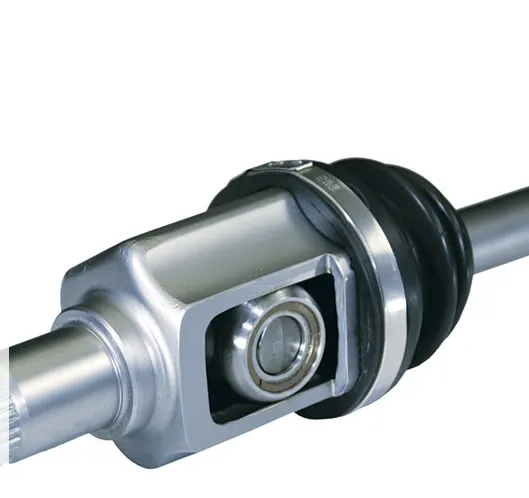
CV joint:Constant-velocity joints allow a drive shaft to transmit power through a variable angle, at constant rotational speed, without an appreciable increase in friction or play. They are mainly used in front wheel drive vehicles. Modern rear wheel drive cars with independant rear suspension typically use CV joints at the ends of the rear axle halfshafts and increasingly use them on the drive shaft.
Part 1 : Quick Return Mechanism
Procedure :
Step1:
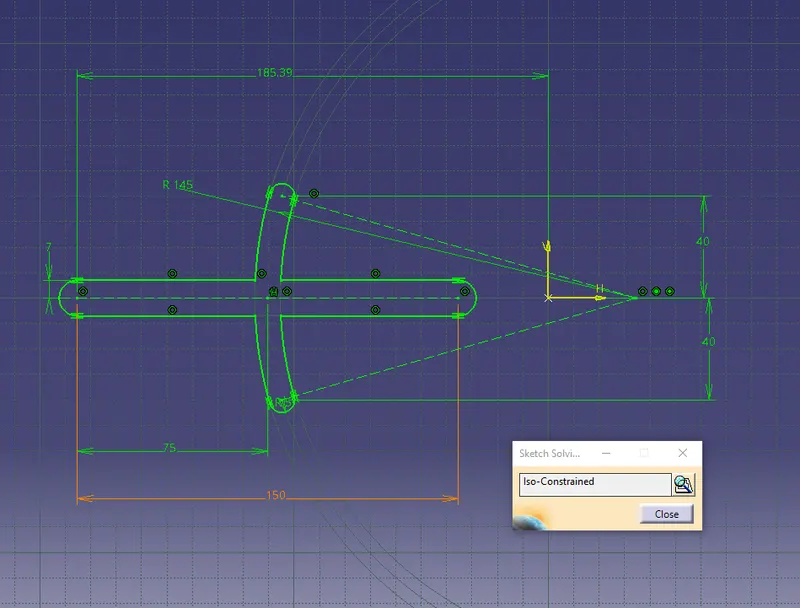
Iso-constrained sketches were created using given 2D drawings . Solids were created as seperate parts using Pad and surface thickening options . Boolean operations were used to obtain final bodies .
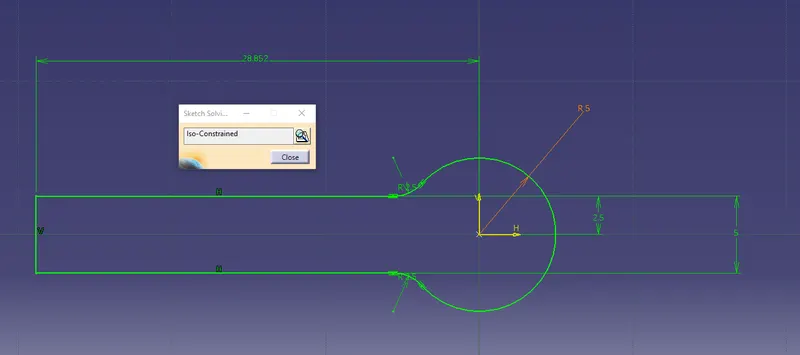
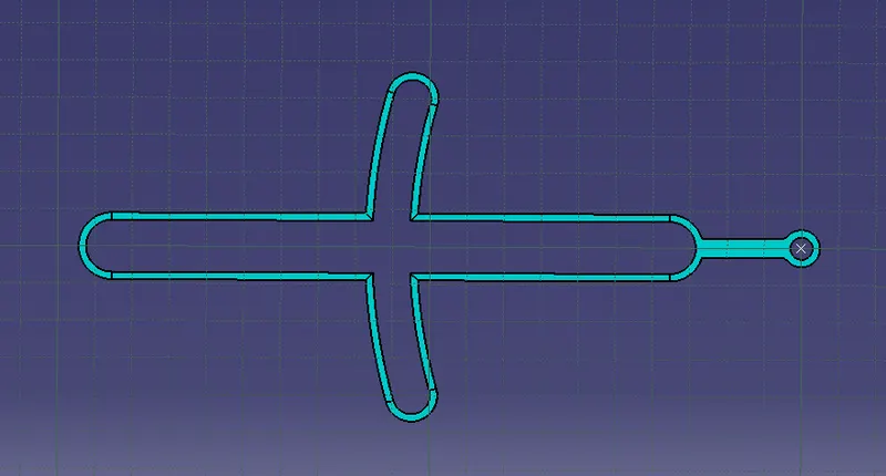
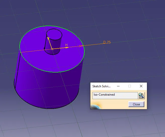
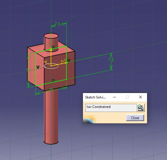
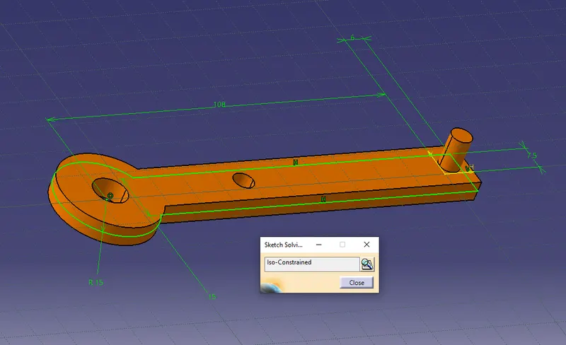
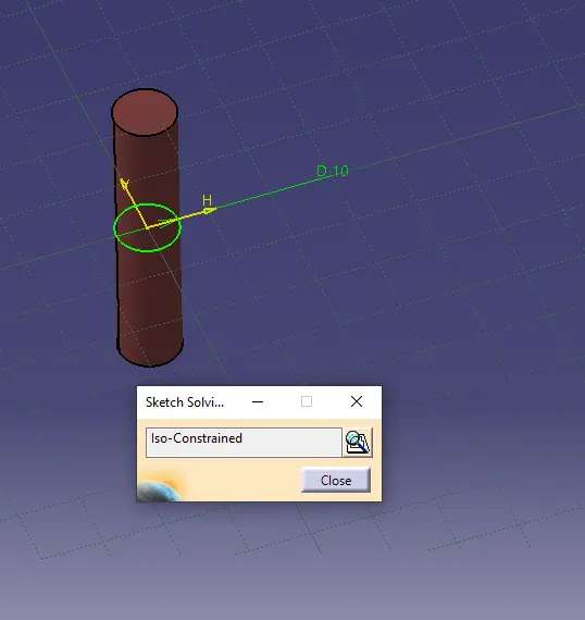
Step 2:
Once all parts were created , Constrains were used to allign all parts together and at fixes locations . Surface constrain were used wherever sliding motion was required . Coincidence were used wherever bodies had to be fixed with respect to each other .
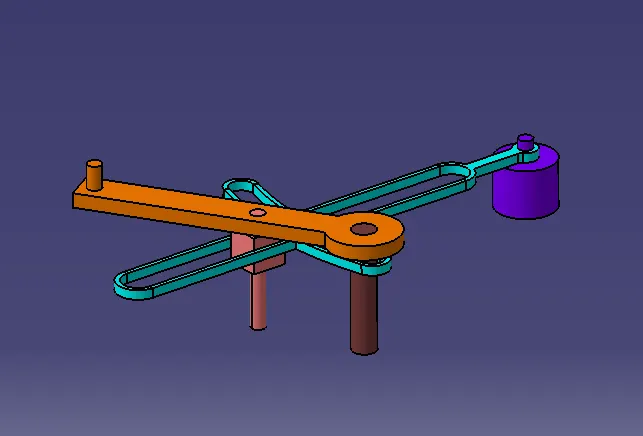
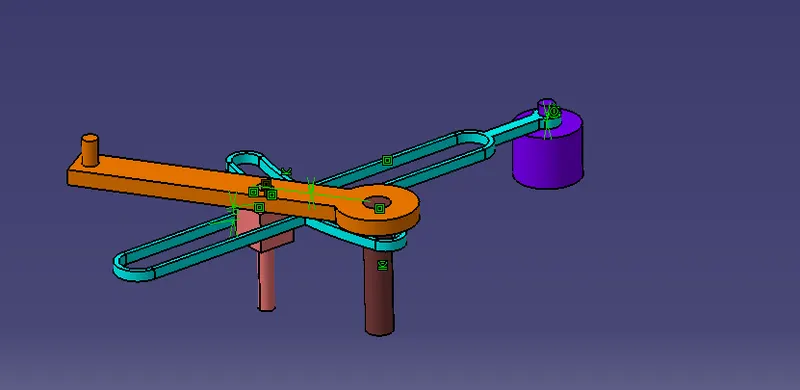
Hence the quick return assembly was created .
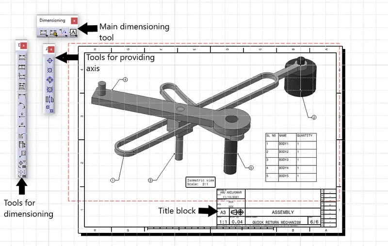
Creation of 2D Drawings for quick return mechanism
Step 1: Drafting workbench was opened and respective views of each bodies were taken .
Step 2: Dimensions were assigned using respective dimension tools after holes and axis were marked .
Step 3: Sketching mode was turned on and each bodies were framed and assigned title blocks as per given drawings .
Part 2 : CV Joint
Procedure :
Step1:
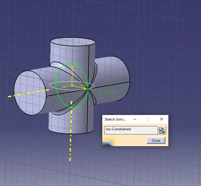
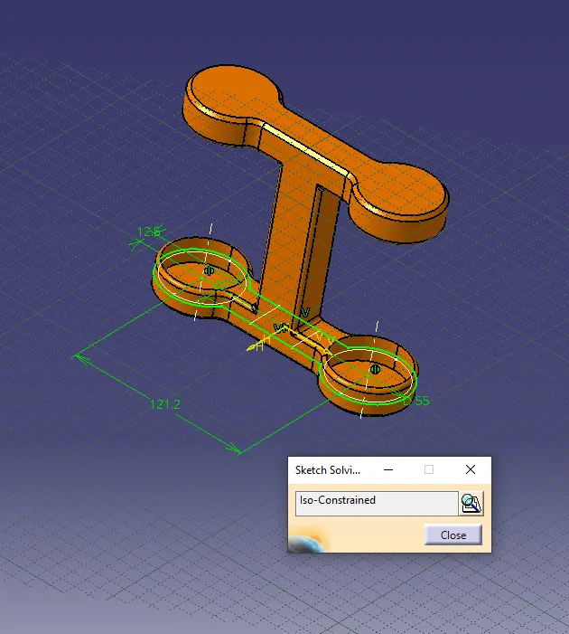
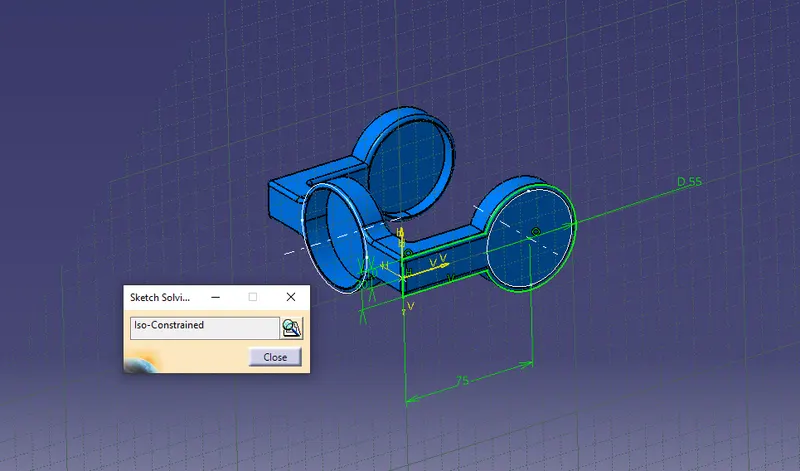
Iso-constrained sketches were created using given 2D drawings . Solids were created as seperate parts using Pad and surface thickening options For bodies that were symmetrical , symmetry was used to create body . Boolean operations were used to obtain final bodies .
Step 2:
Once all parts were created , Constrains were used to allign all parts together and at fixes locations . Surface constrain were used wherever sliding motion was required . Coincidence were used wherever bodies had to be fixed with respect to each other .
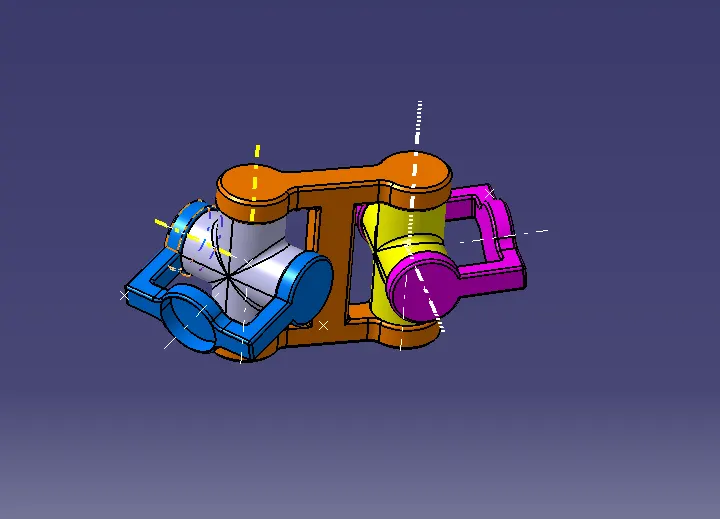
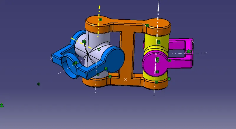
Hence the CV Joint assembly was created .
Creation of 2D Drawings for quick return mechanism
Step 1: Drafting workbench was opened and respective views of each bodies were taken .
Step 2: Dimensions were assigned using respective dimension tools after holes and axis were marked .
Step 3: Sketching mode was turned on and each bodies were framed and assigned title blocks as per given drawings .