Week 11-3D Tetra Meshing Challenge
Objective: To mesh the given components for 3D tetramesh with given quality.
Procedure:
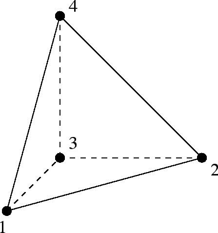
A 3D tetra element is made of four tria faces and four nodes as shown below.
The main quality to be checked for a tetra element is its height. A tetra has four nodes and hence four heights from each node and its opposite face. The ratio of height and square root of the base area is taken into consideration for checking the failure criteria. This ratio is called as tet-collapse. The minimum of the four ratios is compared with the given tet-collapse value.
There are three ways we can proceed for creating tetra mesh.
1. Create 2D mesh on the surface and use tetra mesh option for creating 3D tetras elements using the 2D elements.
2. Create a 3D tetra mesh using Quick Tetra mesh option using Utility tab.
3. Volume tetra mesh option under 3D deck.
We will discuss all the three using different components.
CASE 1 : TetraMesh Generation Method: 2D to 3D Conversion
Housing Model:
This model has two components as shown in the images below.
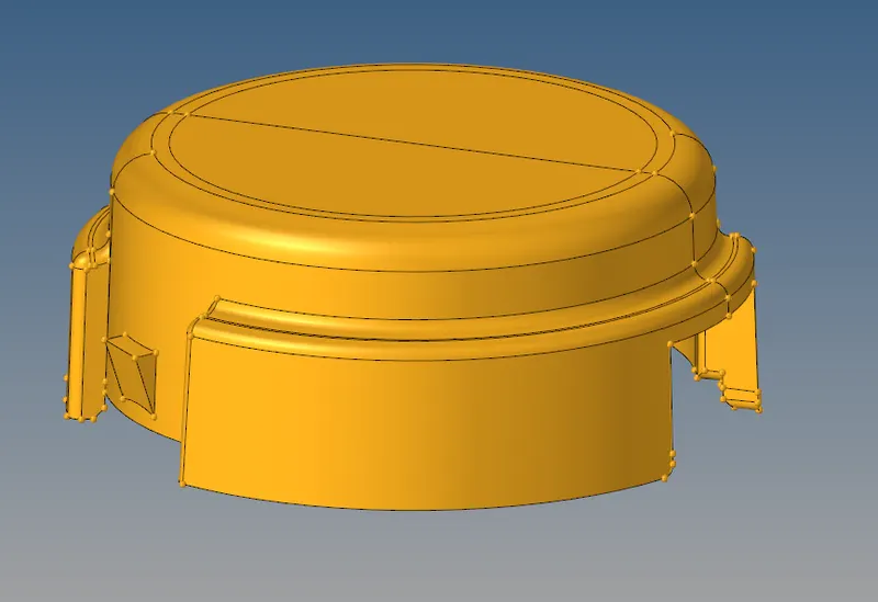
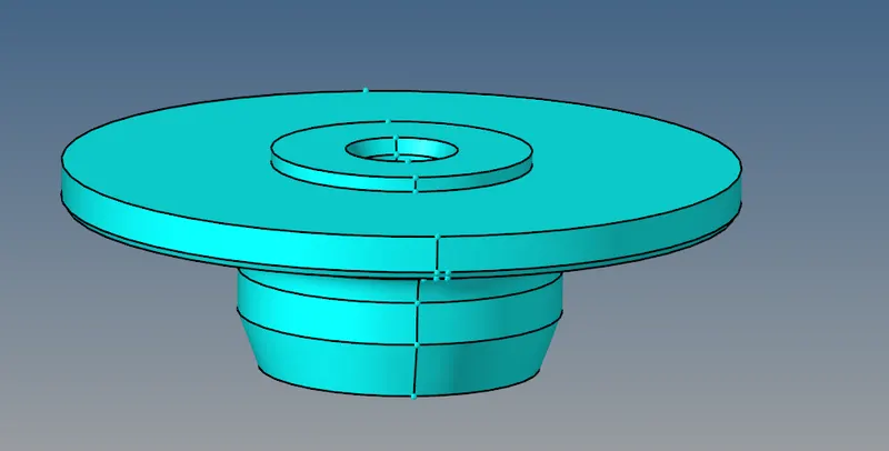
Using the first method of creating 2D and then 3D, this inner component is meshed.
In this case we are doing tetra element by using Tetra mesh but this not given the result so doing another option that is Quick tetra mesh. Select component, mesh size and element size and click on mesh.
for Create 2D mesh on the surface and use tetra mesh option for creating 3D tetras elements using the 2D elements.
so geometry required topology cleanup we can did it by manualy using F11 toggle.
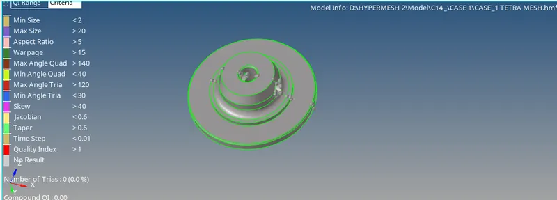
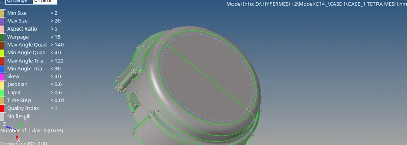
once geometry cleanup are done we have to create 2D mesh element for creating Tetra by using 2d element.
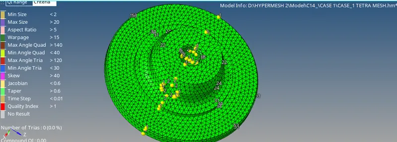
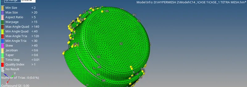
Tet collapse.
after deleting element confi. of 2d element we foond Tetra mesh.
The overall tetra mesh and the tetra collapse is shown in Out of these no element has failed for tet-collapse.
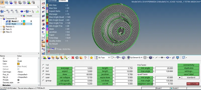
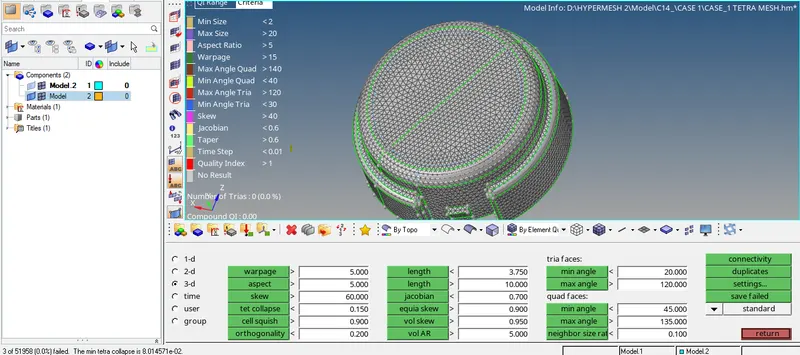
3D. TETRAMESH
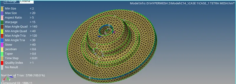
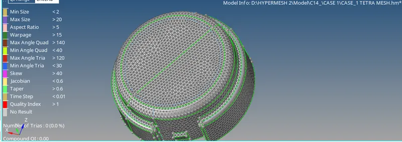
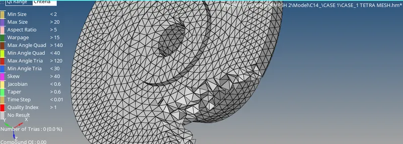
In above image we can see that tetra element by using mask tool mask the small portion of geometry and we can see the tetra mesh.
Here, there is no need to create a 2D mesh. Selection of the solid components or the enclosed surface is required and tetra mesh is generated after specifying the parameters like element length and cleanup tools.
3D>tetramesh>Volume tetra
In the above image we can the the tetra mesh and assembly of geometry.
CASE 2
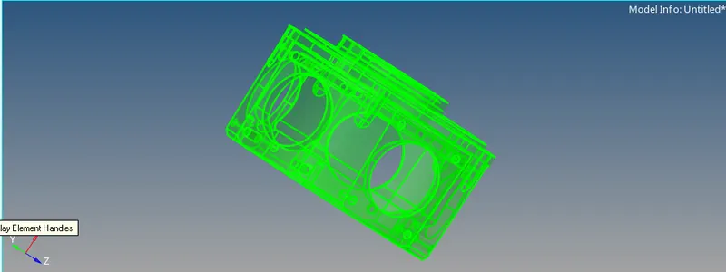
Import the module geometry for the second case as shown below.
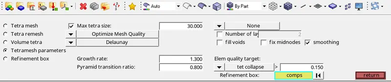
VOLUME TETRA MESH PARAMETER
after importing we can go throught the 3D Tetramesh tool by using Volumatric Tetra meshing tool and put
tetra mesh parameter as per given and check fill void, fix midnode and smoothing .
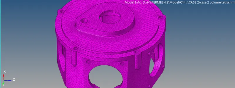
The minimum tet-collapse is 0.151.
TETRA MESH
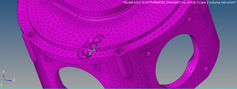
TETRA MESH ELEMENT
CASE 3
TetraMesh Generation Method: Quick Tetra Mesh/ Volume Tetra Mesh
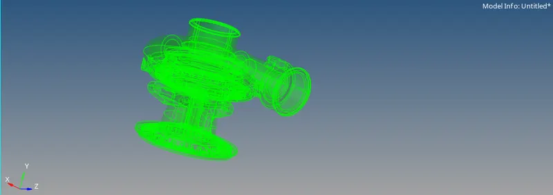
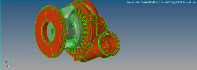
Model 3 suspension and wheel components. A wheel hub, kuckle joint.
As described before, the same procedure is followed to get tetra mesh in this model.
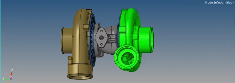
conver to topo and by element quality we are found that there are four component are geometry and one are surface.
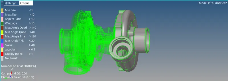
getting tetra mesh by using quick tetra mesh method for surface component.
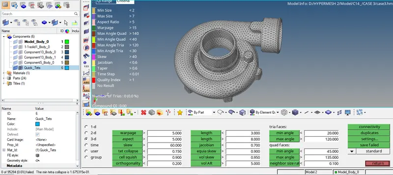
tetra collapse is shown above image in Out of these no element has failed for tet-collapse.
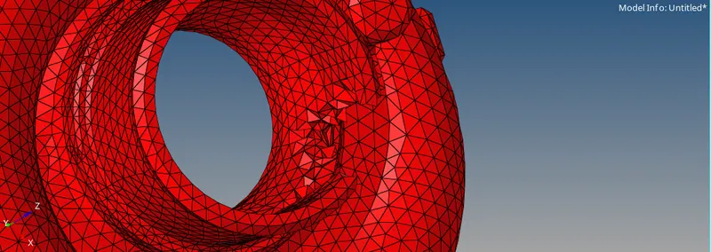

now other four component are are in solid phase we can getting tetra mesh by using Tetramesh tool and volumatric tool.
or we can doing by deleting solid from geometry and go through surface by using 2D to 3D tetra mesh.
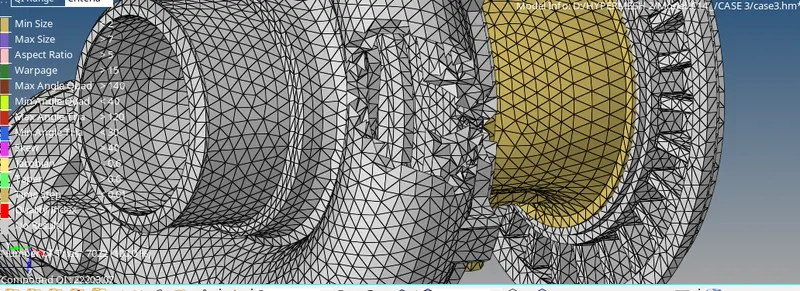
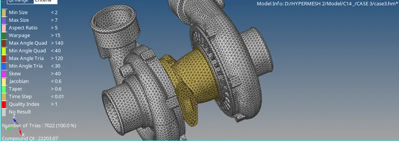
The overall tetra mesh and the tetra collapse is shown in Out of these no element has failed for tet-collapse.
Conclusion: Tetra meshing in Hypermesh with different methods is studied here. The failure criteria for tetra elements is studied and understood what tetra collapse is. The methods to eliminate tetra collapse is also studied.