Week 11 - 3D Contacts
AIM:-
To setup a 3D contact between CAM and Follower and plot the displacement in Y direction
THEORY
In MotionSolve the contact collision algorithm searches for proximity between geometries when any penetration between the two sets of geometries occurs, a force based on the defined contact properties is generated.
There are 3 predefined contact models:
- Impact
- Poisson
- Volume
User can define his own force model using subroutine in case none of the
predefined models are suitable.
Contact Forces
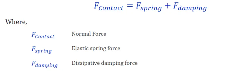
Normal Force
It has two components and each of the predefined method has its own way of computing these components
Friction Force
It is calculated using the Coulomb friction model
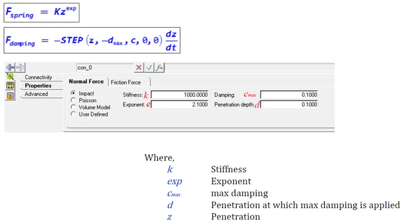
Impact Contact Model
The Impact Contact model determines the elastic and damping forces using below equations:
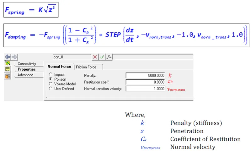
Poisson Contact Model
The Poisson contact model determines the elastic and damping forces using below equations:
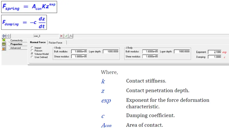
Volume Contact Model
The Volume contact model determines the elastic and damping forces using below equations:
CREATION OF MODEL
Lets create Cylinder Models using Points with Parametrization
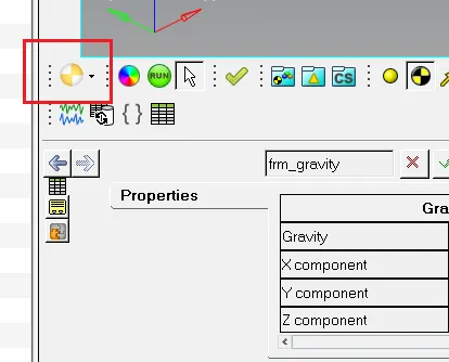
Step 1 :- Start the Hyperworks and change the list to motion View
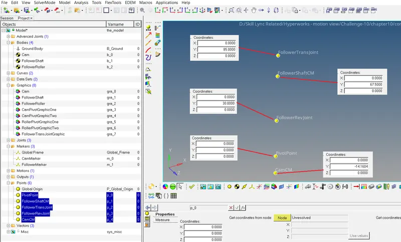
Step 2 :- Create a Points Pivotjoint, FollowershaftCM, Followertransjoint, FollowerRevjoint, CamCM as shown in image below
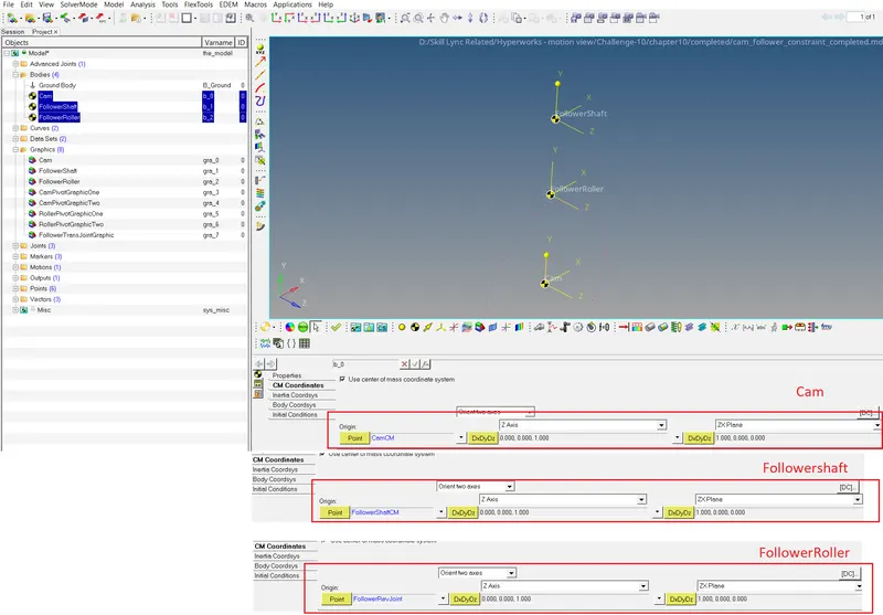
Step 3 :- Create a Bodies Cam, Followershaft, FollowerRoller as shown in image below
Step 4 :- Create Graphics as specified below
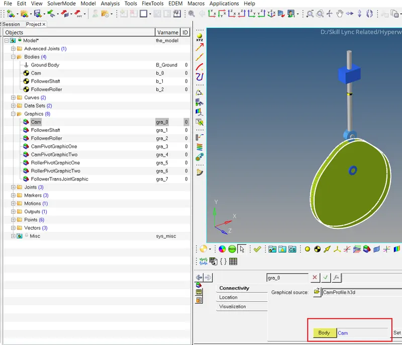
CAM – Import the CAD model as .h3d as shown in image below
Followershaft – Create Graphic as shown in image below
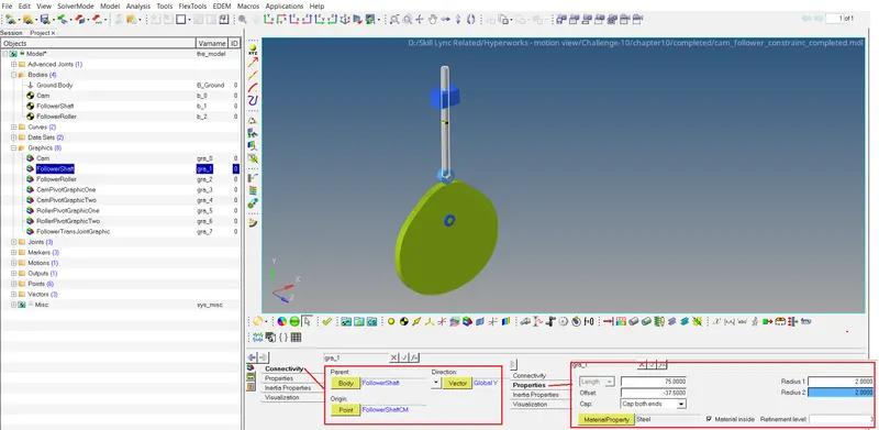
FollowerRoller – Create Graphic as shown in image below
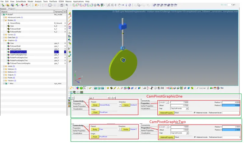
CamPivot - We have to create two Graphic as CamPivotGraphicOne & CamPivotGraphicTwo as shown in image below
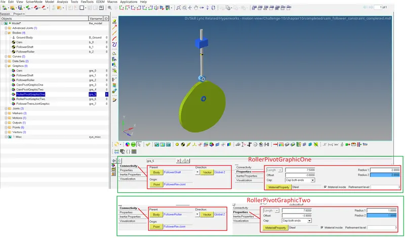
RollerPivot - We have to create two Graphic as RollerPivotGraphicOne & RollwePivotGraphicTwo as shown in image below
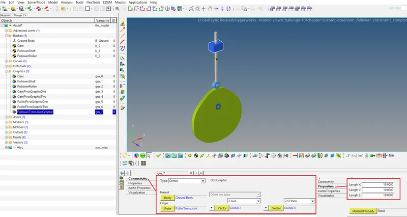
FollowerTransJointGraphic - Create Graphic as shown in image below
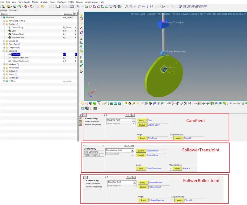
Step 5 :- Create Joints Campivot, FollowerTransJoint, FollowerRollerJoint as shown in image below
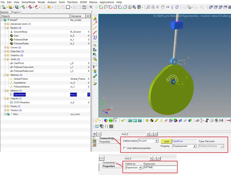
Step 6 :- Create a motion in Campivot as shown in image below.
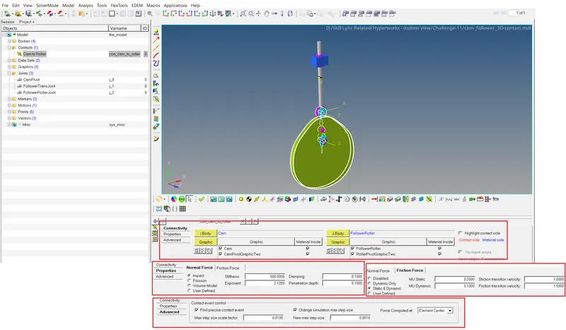
Step 7 :- Create a Contact Between the Cam and FollowerRoller as shown in image below
Step 11 :- Run the Simulation and Plot the graph for the Displacement in Y direction
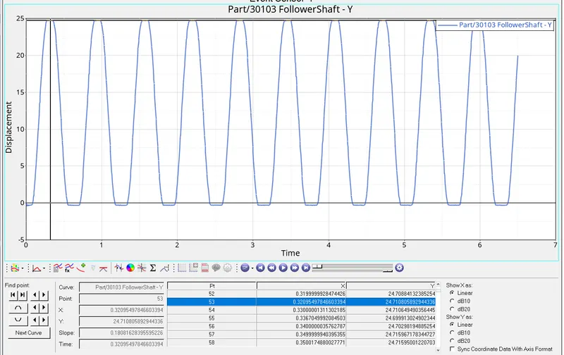
It is seen Max. Displacement in Y direction is 24.71mm
Conclusion
In CVCV joint method of Cam and Roller the Y displacement is 25mm and By Contact method between Cam and Roller the Displacement in Y direction is 24.71mm may be due to Friction force effect.