Week 10 Thermal Management
Q) Prepare a report summarizing thermal management techniques for electric car battery pack.
ANS -
thermal management techniques for electric car battery pack. and in that battery pack made of no of cell we will see lithium cell
There are many types of lithium-ion battery which are named by cathode oxides and
each one has its own characteristics as followings:-
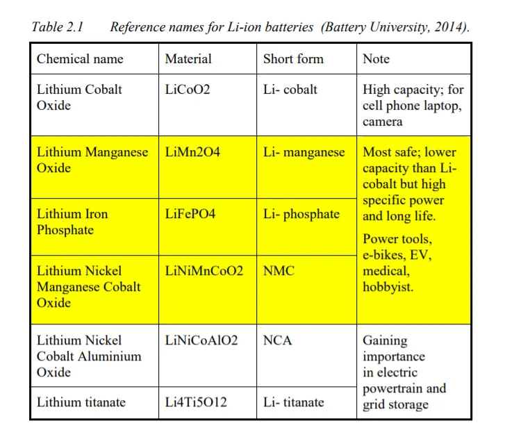
three types of lithium batteries are particularly suitable for an EV battery, namely LiMn2O4, LiFePO4, and LiNiMnCoO2
Thermal Issues of Li-ion battery
Lithium-ion cells performance depends on both the temperature and the operating
voltage. Lithium-Ion cells work well when cells operate within limited voltage and
temperature. Otherwise, damage will occur to the cells and will be irreversible.
In over-voltage situations the charging voltage exceeds the bearable cell voltage,
resulting in excessive current flows and at the same time, it causes two problems.
At excessive currents the Lithium-ions are deposited more rapidly than intercalation to
the anode layers, Lithium ions are then deposited on the surface of the anode as metallic
Lithium. This is Lithium plating. It gives rise to the reduction in the free Lithium ions
and an irreversible capacity loss. (Electropaedia, 2014). There are two types of metal
lithium plating, namely homogeneous lithium plating and heterogeneous lithium
plating, but the lithium plating is dendritic in form. Eventually it can result in a shortcircuit between the electrodes.
As with over-voltage, under-voltage also brings about problems which give rise to the
breakdown of the electrode materials.
For the anode, the copper current collector breaks down. It causes the increase of battery
discharge rate and battery voltage, however, the copper ions are precipitated as metal
copper which is irreversible. The situation is dangerous for it can result in short-circuit
between anode and cathode.
For the cathode, the cobalt oxide or manganese oxide will be decomposed after many cycles under low voltage. Meanwhile, oxygen will be released and the battery suffers from capacity loss.
The battery temperature should be controlled carefully. Both excess heat and lack of
heat will brings about problems.High temperature increases the reaction rate with higher power output, however, it also
increases the heat dissipation and generates even higher temperatures. Unless heat is
dissipated quicker than heat is generated, the temperature will be higher and finally a
thermal runaway will result.
Thermal runaway consists of several stages and each stage will give rise to more irreversible damage to cells.
Operating Requirements
The battery temperature should be controlled within temperature limits to avoid the
thermal issues and improve the performance. The temperature range affects the battery
power and battery cycle life, see Figure 2.2 and Figure 2.3. At the same time, the
temperature distribution should be even to guarantee the battery performance and lifetime. That is also the reason why the battery thermal management system is necessary to the battery system.
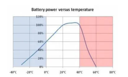
Figure 2.2 Battery power and temperature
When temperature ranges from 20°C to 40°C, battery power reaches maximum, see
Figure 2.2
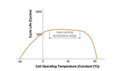
Figure 2.3 Cycle life and temperature
The cycle life goes down slowly below 10°C because of anode plating and drops off
quickly above 60°C due to the breakdown of electrode materials, see Figure 2.3.
Generally, the temperature must be controlled between 20°C and 40°C to ensure the
performance and cycle life. Moreover, the temperature distribution is controlled under
5K to keep the safety and lifetime of battery (Pesaran, 2002). In addition, ventilation is
also essential to the battery system and should be taken into account.
Battery Thermal Management Systems (BTMS)
the battery pack for safety, performance (both power and capacity) and lifespan reasons should be stored in a controlled surrounding
where the temperature is controlled and there is no risk of thermal runaway. According
to a foundational research (Pesaran, 2001), the BTMS should be equipped with four essential functions to ensure the right operation conditions of the battery pack:
1. Cooling
Due to inefficiency, battery cells will not only generate electricity but also heat.
This heat should be moved from the battery pack when battery temperature
reaches the optimum temperature or even in advance. Thus, a cooling function
is required in BTMS.
2. Heating
In cold climates, battery pack temperature probably falls below the lower
temperature limit. Hence, a heating function, such as PTC heater, is required to
assist the battery pack to reach the proper temperature range in a shorter time.
3. Insulation
In extreme cold or hot weather, the temperature difference between the inside
and outside of the battery pack is much larger than that in mild weather. Battery
temperature will thus fall (cold) or rise (hot) sooner out of the proper
temperature range. To prevent this, good insulation can slow down the falling
or rising of battery temperature, especially when the vehicle is parked outdoors.
4. Ventilation
Ventilation is required to exhaust the hazardous gases within battery pack. In
some systems, such as air systems, this function is combined with cooling and
heating functions.
In the following sections, different technologies of heating and cooling will be
introduced in detail and their possibility and ease of ventilation will be evaluated.
Insulation affects mainly stationary conditions rather than driving conditions, so it will
not be further discussed in this thesis.
Technologies of BTMS
Air Cooling and Heating
Air systems use air as the thermal medium. The intake air could be direct either from
atmosphere or from the cabin and could also be conditioned air after a heater or
evaporator of an air conditioner. The former is called passive air system and the latter
is active air system. Active systems can offer additional cooling or heating power. A
passive system can offer some hundreds of watts cooling or heating power and an active
system power is limited to 1 kW. (Valeo, 2010)
Because in both cases the air is supplied by a blower, they are also called forced air
systems. The following figure shows a schematic description of systems.
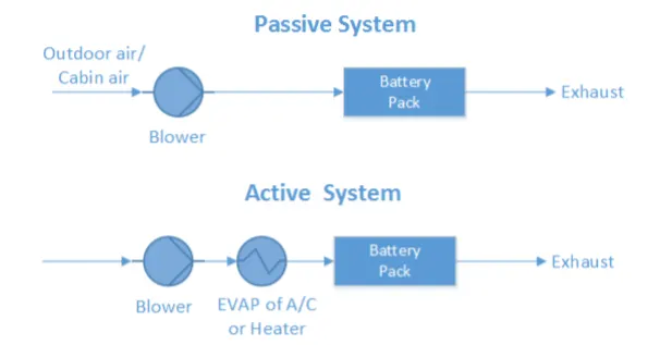
Figure 3.1 Forced air systems (passive and active).
Note that the air system offers full functions of heating, cooling and ventilation. There
is no need to build an additional ventilator, but it must be noted that the exhaust air
cannot be returned to the cabin again. In some cases, a heat recovery unit (air-air heat
exchanger) is mounted after the battery pack in order to recovery the heat from the
exhaust air. It can prevent mixture of exhaust air with intake air and at the same time
provide an extra saving potential. The forced air system with heat recovery is presented
below.
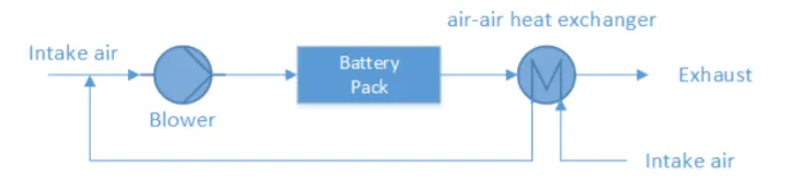
Figure 3.2 Forced air system with heat recovery
Liquid Cooling and Heating
Besides air, liquid is another heat transfer fluid to transfer heat. There are generally two
groups of liquids applied for thermal management systems. One is dielectric liquid
(direct-contact liquid) which can contact the battery cells directly, such as mineral oil.
The other is conducting liquid (indirect-contact liquid) which can only contact the
battery cells indirectly, such as a mixture of ethylene glycol and water. Depending on
the different liquids, different layouts are designed. For direct-contact liquid, the normal
layout is to submerge modules in mineral oil. For indirect-contact liquid, a possible
layout can be either a jacket around the battery module, discrete tubing around each
module, placing the battery modules on cooling/heating plate or combining the battery
module with cooling/heating fins and plates. (Pesaran, 2001) Between these two groups,
indirect contact systems are preferred in order to achieve better isolation between
battery module and surroundings and thus better safety performance.
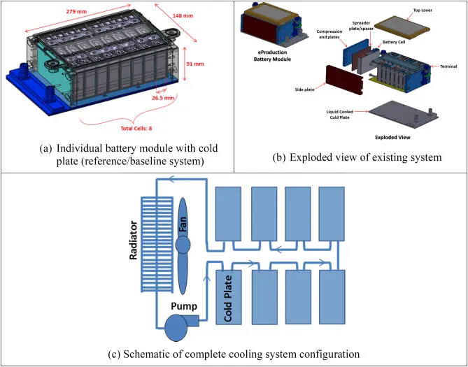
By different heat-sinks for cooling, liquid systems can also be categorized into either
passive systems or active systems. In passive liquid system, the heat-sink for cooling is
a radiator. This system has no ability to heat. Figure 3.3 presents the systematic scheme
of a passive liquid system. Heat transfer fluid is circulated by the pump within a closed
system. The circulating fluid absorbs heat from battery pack and releases heat via a
radiator. The cooling power depends strongly on the temperature between ambient air
and battery. Fans behind the radiator can improve the cooling performance, but if
ambient air is higher than the battery temperature or the difference between them is too
small, the passive liquid system becomes ineffective.
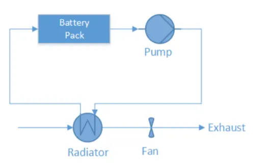
Figure 3.3 Passive liquid cooling system.
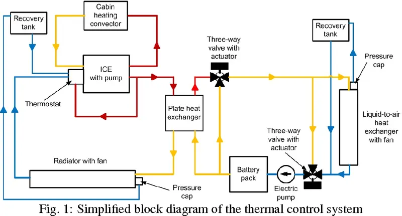
Figure 3.4 shows the systematic scheme of an active liquid system. There are two loops.
The upper is called the primary loop and the lower the secondary loop. The primary
loop is similar to the loop in a passive liquid system, where the heat transfer fluid is
circulated by pump. The secondary loop is actually an air conditioning loop (A/C loop).
The upper heat exchanger instead of being a radiator works as an evaporator (EVAP)
for cooling operation and connects both loops. During heating operation, the 4 way
valve will be switched, and the upper heat exchanger works as a condenser (COND)
and the lower heat exchanger works as an evaporator. The heating operation loop is
also called heat pump loop.
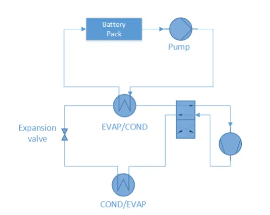
Figure 3.4 Active liquid cooling system
Direct Refrigerant Cooling and Heating
Similar to active liquid systems, a direct refrigerant system (DRS) consists of an A/C
loop, but DRS uses refrigerant directly as heat transfer fluid circulating through battery
pack. The systematic layout is in Figure 3.5.
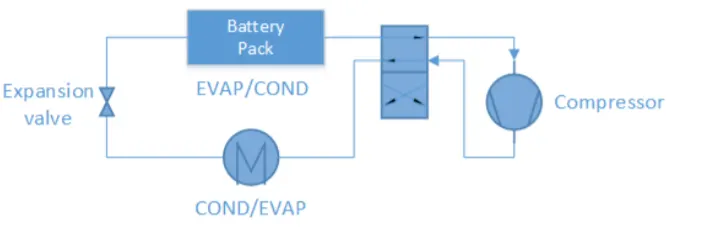
Figure 3.5 Direct refrigerant cooling system
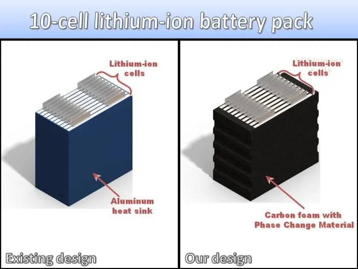
PCM
During melting, heat is absorbed by PCM and is stored as latent heat until the latent
heat is up to the maximum. The temperature is kept at melting point for a period and
the temperature increase is delayed. Therefore, PCM is used as conductor and buffer in
battery thermal management systems. Figure 3.6 shows the working mechanism of
PCM on battery cells. Also, a PCM is always combined with air cooling system or
liquid cooling system to manage the battery temperature.
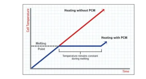
Figure 3.6 The working mechanism of PCM on battery cells
https://www.youtube.com/watch?v=wJqEKvEMB68&ab_channel=AdvancedCoolingTechnologiesInc.
Thermo-electric Module
To improve cooling/heating power of passive air systems, there are two possible
upgrades. One is through thermo-electric modules, which will be introduced here. The
other is a heat pipe will be discussed in below Section. Thermo-electric module can convert electric voltage to temperature difference and viceversa. Here the former effect is adopted. That means it transfers heat through the module
by consuming electricity directly. The schematic structure is presented in Figure 3.7.
Two fans are installed to improve heat transfer by forced convection. To combine a
passive air system with thermo-electric module, the combined system is able to cool
down the battery even lower than the intake air temperature, but the power is still
limited to around some hundreds of watts and less than one kW. (Valeo, 2010) It’s easy
to switch between cooling and heating operation. To achieve that, the poles of
electrodes need to be reversed
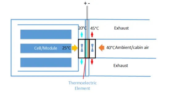
Figure 3.7 Thermoelectric cooling/heating system
Heat Pipe
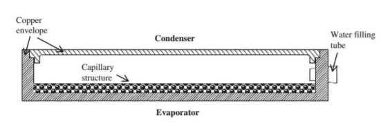
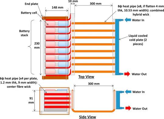
Besides thermo-electric modules, a heat pipe is another way to upgrade passive air
systems. The structure of a heat pipe is shown in Figure 3.8. The flat copper envelope
of the heat pipe was under partial vacuum. The capillary structure is made of sintered
copper powder. The heat pipe uses water as the working fluid. Water on the evaporator
side will absorb heat and become vapour lower 100°C due to low pressure inside. Water
on the condenser will dissipate heat to the surrounding and become liquid again. This
cycle repeats again and again.
The following figure shows the schematic description of a heat pipe cooling system. A
battery as heat source sits below the heat pipe (on the evaporating side). Cooling fins
as heat sinks are on the heat pipe (on the condensing side). According to the conclusion
of an experiment (Tran, 2014), heat pipe cooling system can reduce the thermal
resistance by 30% under natural convection as compared to without heat pipe . A
thermal resistance reduction of 20% under low air velocity convection is possible.
Note that, in comparsion to thermo-electric, a heat pipe is more reliable, because there
are no moving parts and no energy consumption. However, a heat pipe is unable to heat
the battery due to its fixed structural layout.
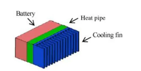
Figure 3.9 Scheme of heat pipe cooling system.
some images
as per question we summarizing thermal management techniques for electric car battery pack.
for reference pdf is attach for more info