Week 10 - Simulating Combustion of Natural Gas.
Aim and its objective:
Utilizing ANSYS FLUENT, simulate the combustion of natural gas inside a burner.
- Convert the combustor 3D model to 2D and save it as a new model before importing it into Spaceclaim.
- To properly mesh the combustion engine model.
- The correct solver model and its parameter must be set up in the solver settings.
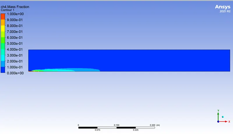
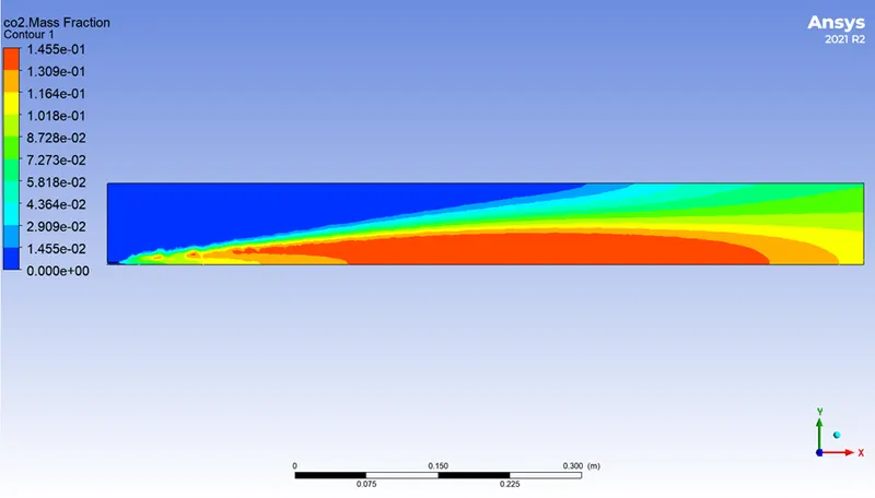
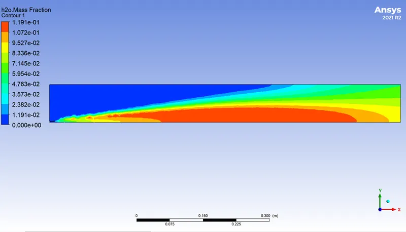
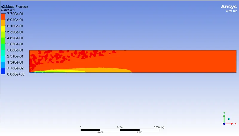
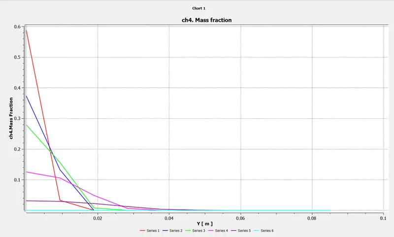
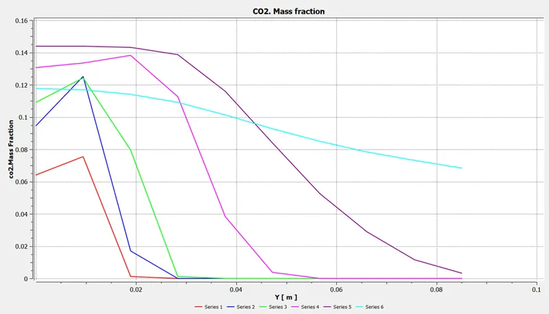
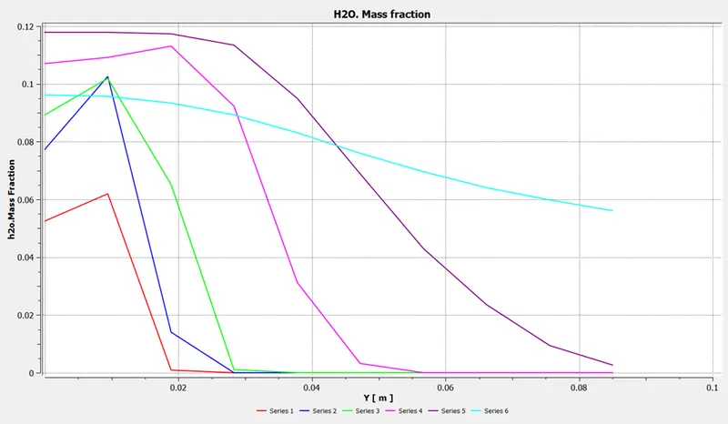
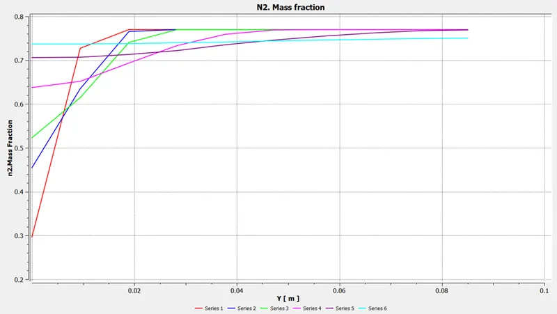
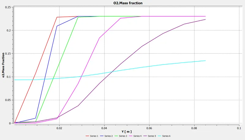
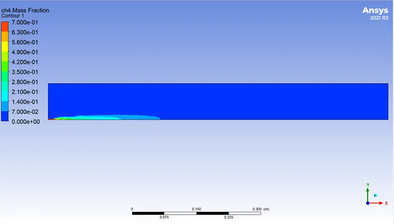
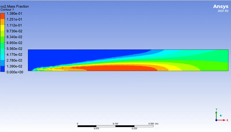
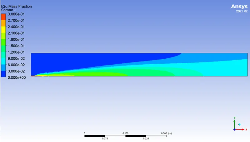
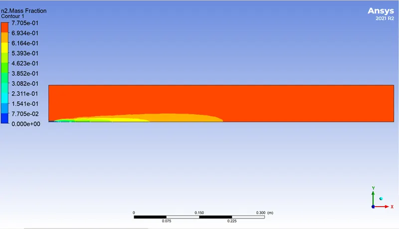
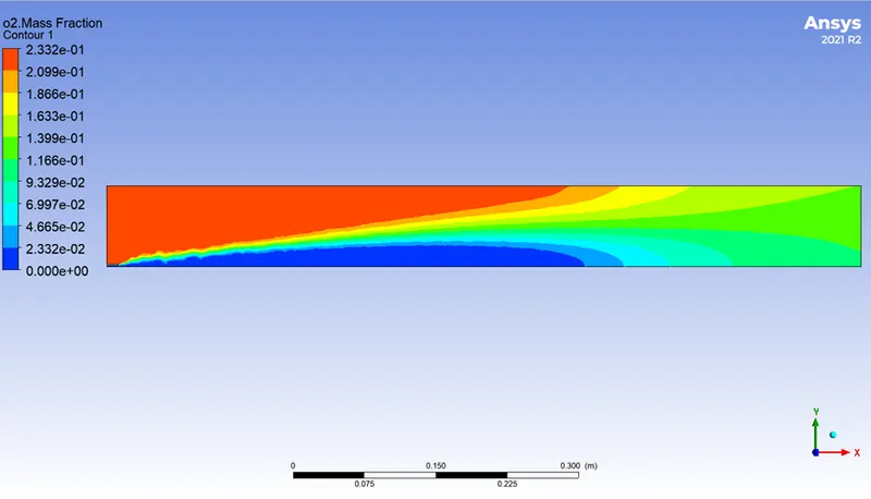
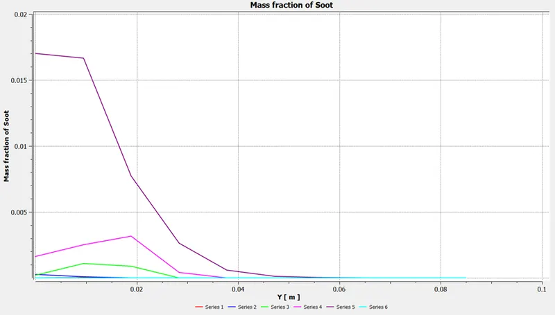
- Plots showing the mass fraction of the combustion species (CO2, H2O, O2, N2, CH4, NOx, and soot forming) should be produced.
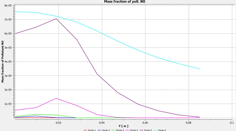
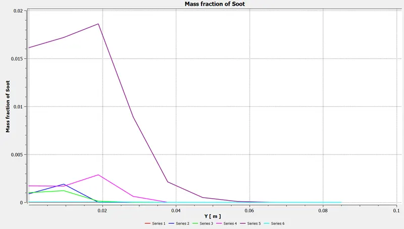
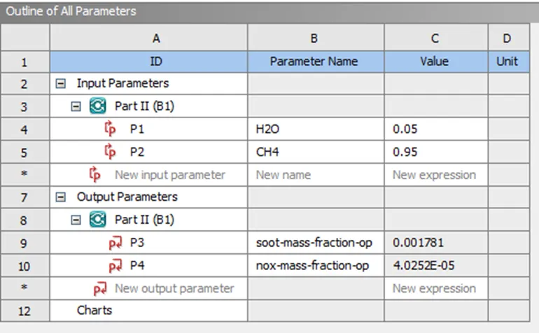
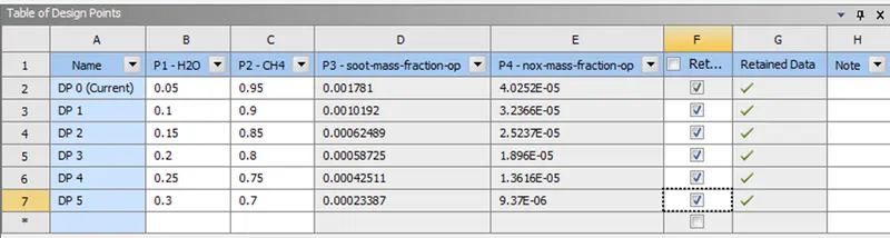
- To reduce the generation of NOx and soot during combustion, run the simulation while adding water to the fuel in the range of 5% to 30%.
Theory:
Several combustion models are available for CFD modeling, including:
- The eddy dissipation model is based on the idea that chemical reactions occur quickly in comparison to flow-related transport processes. At the molecular level, reactants instantly combine to generate products. The model makes the assumption that the time needed to mix reactants at the molecular level might directly affect the reaction rate. For usage in a variety of turbulent reactive flows, including premixed and diffusion flames, the eddy dissipation model was created. This model has been frequently used in the forecasting of industrial fires due to its simplicity and reliable performance in the prediction of turbulent reactive flows.
- The computation of reaction rates as specified by the molecular interactions between the constituents of the fluid is made possible by the finite-rate chemistry model. When it comes to flames, where chemical reaction rates may be slower than reactant mixing rates, it can be paired with the eddy dissipation model. The finite-rate chemistry model works well when the chemical time scale is rate-limiting. Both laminar and turbulent flows can be used in conjunction with this model.
- For the price of solving just two transport equations, the flamelet model may offer information on minor species and radicals like CO and OH as well as account for turbulent temperature fluctuations and local extinction at high scalar dissipation rates. Only two-feed systems are compatible with the model, which needs a chemistry library as input. The model is only applicable to unpremixed systems.
- By resolving a scalar transport equation for the development of the reaction, the extended coherent flame model (ECFM) and the burning velocity model (BVM) simulate the spread of a premixed or partially premixed flame. The turbulent burning velocity is modeled by the BVM using an algebraic correlation. An additional transport equation for the density of the flame surface is solved when utilizing the ECFM to close the turbulent burning velocity.
- The mass fraction and mole fraction of each species will be determined using this equation.

Procedure:
PART I
Pre-processor
Geometry:
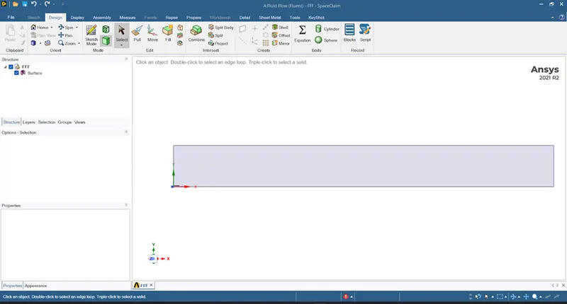
- Because solving a 3D model takes a long time, we developed a two-chambered combustion engine in CAD software and imported it into Spaceclaim as a 2D model.
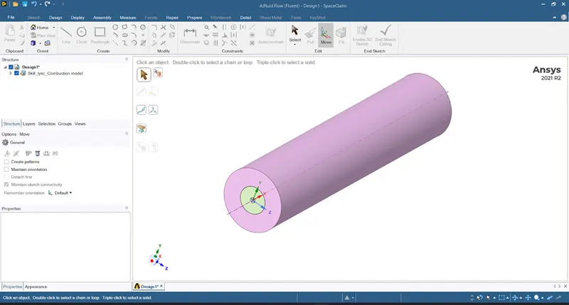
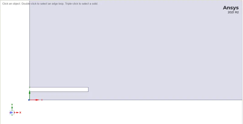
- At the start of the combustion process, there is a slot that indicates the separation of the fuel and air. Because the 2D model's half is symmetric, we chose it. For both portions, the simulation results will be identical.
 .
.
Meshing and its parameters:
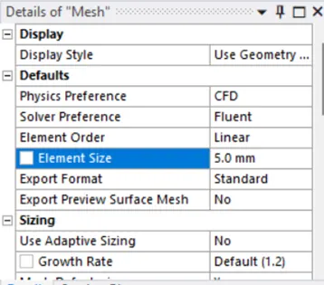
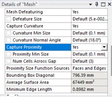
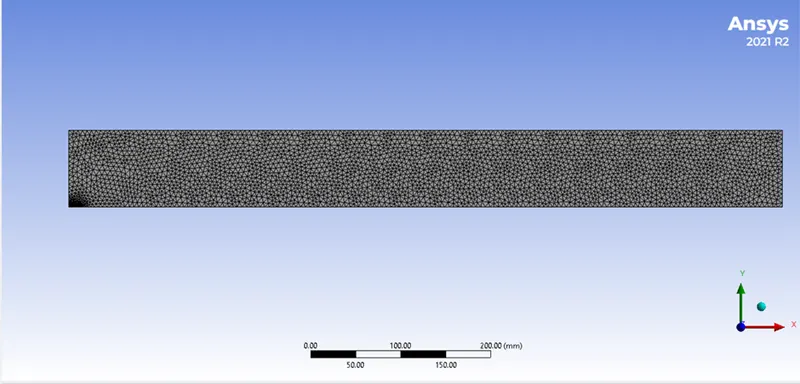
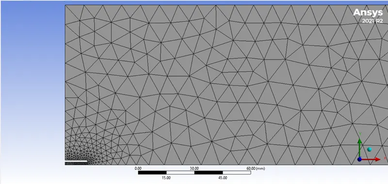
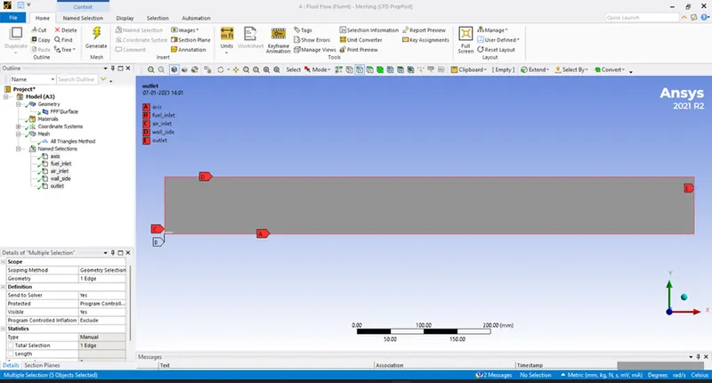
The model was imported from Spaceclaim, and a 5mm element-size tia mesh was deployed. The creation of named selections, such as fuel inlet, air inlet, wall, axis, etc., served as the boundary conditions for the solver setup.
| Mesh size | Nodes | Elements |
| 5 mm | 3342 | 6265 |
Mesh quality:
Named selection (Initial condition):
Solution set-up
Physics set-up:
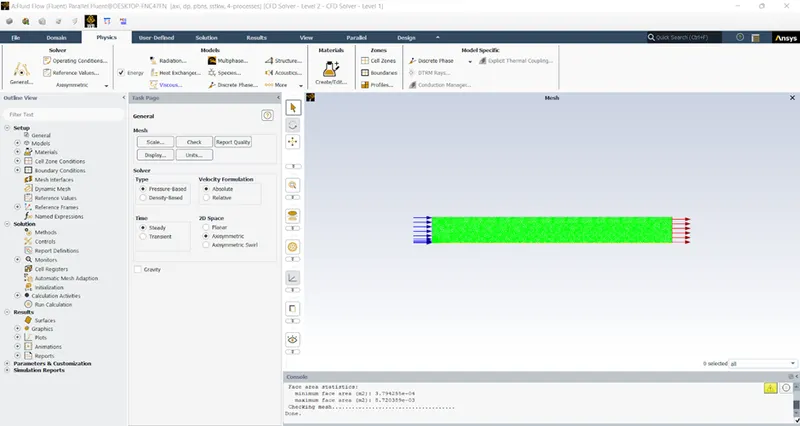
Since the fluid flow velocity is quite low, we started with a general configuration and then moved on to a pressure-based steady-state solver. Due to its symmetry, axisymmetry was chosen for 2D space.
| Solver type | Pressure-based time |
| State type | Steady state |
| Models | Energy on |
| Models |
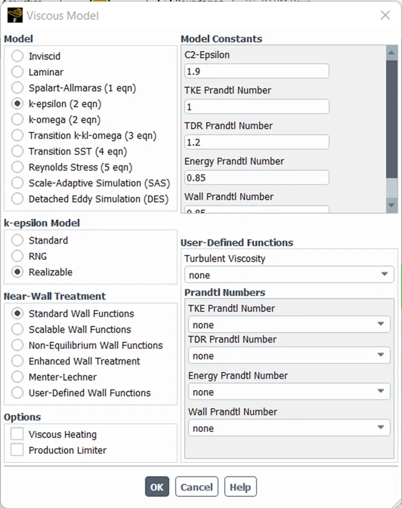
k-epsilon turbulence model
|
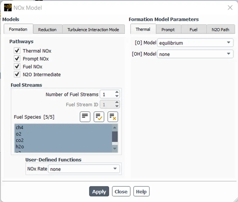
| Models | NOx on |
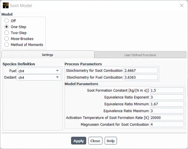
| Models | Soot on |
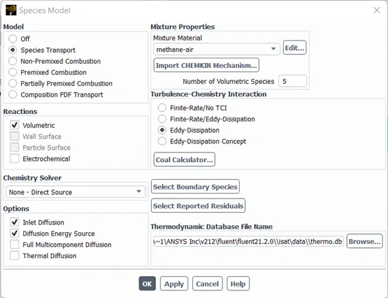
| Models | Species on |
| Solution solver | Hybrid initialization |
Viscous and species model:
Boundary condition:
| Part I | ||||
| Boundary condition | Temperature | Species mass fraction | ||
| Air inlet | 0.5 m/s | 300 K | O2 | 0.23 |
| fuel inlet | 80 m/s | 300 K | CH4 | 1 |
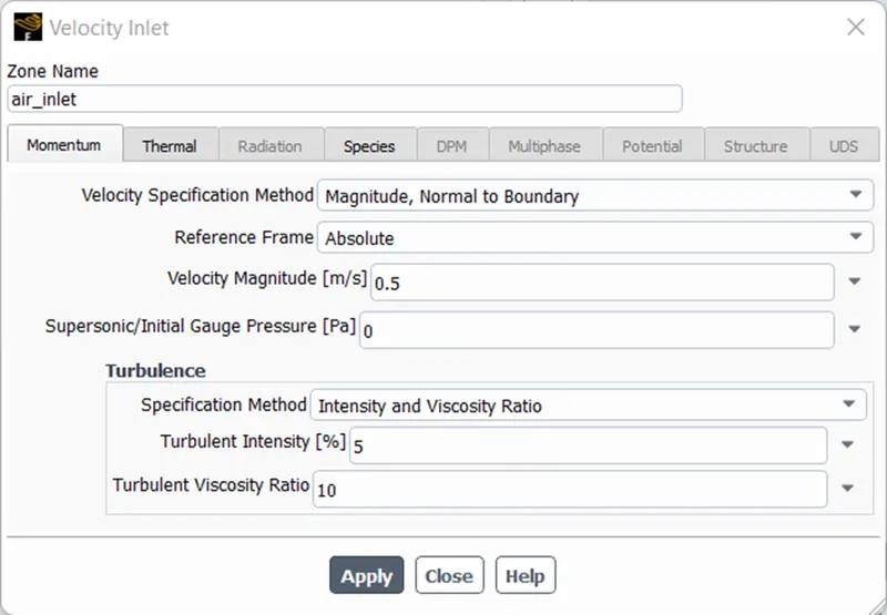
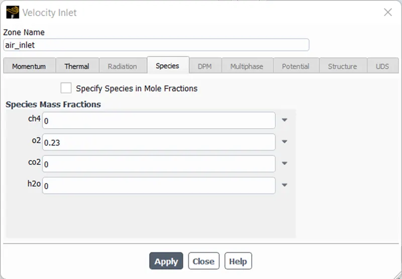
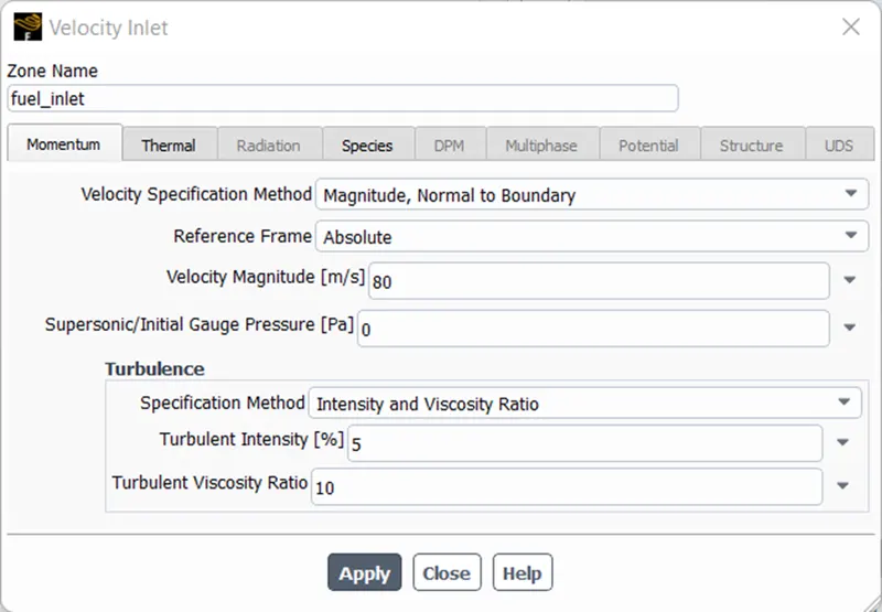
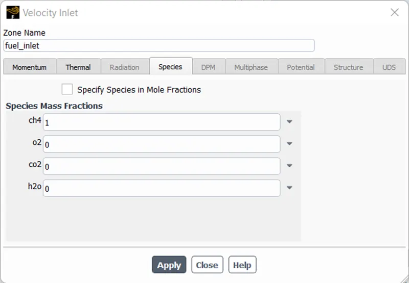
NOx and Soot model of one-step process:
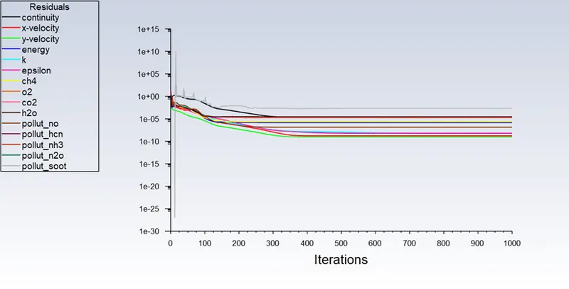
Scaled residuals plot:
Post-processor
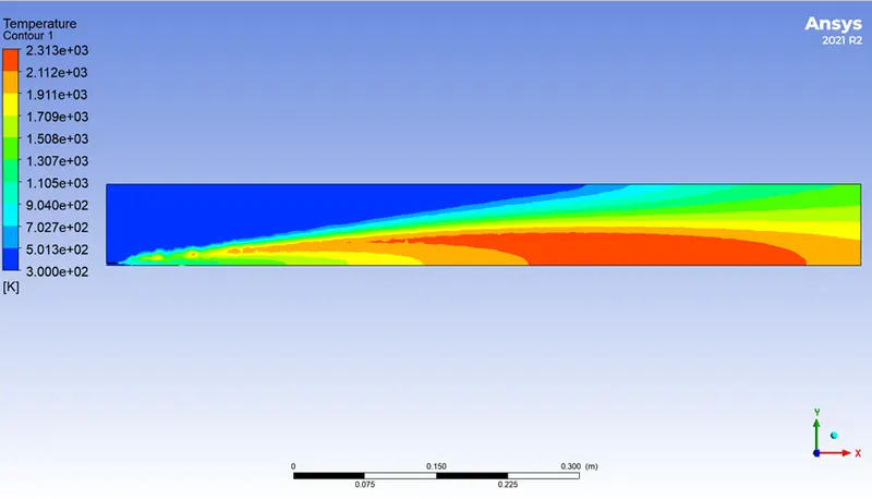
CFD- Post results:
Temperature contour:
CH4 Mass fraction contour:
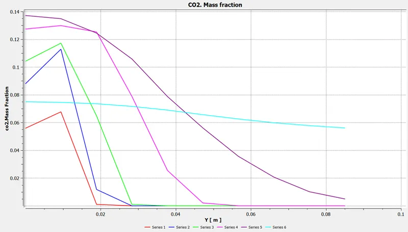
CO2 Mass fraction contour:
H2O Mass fraction contour:
N2 Mass fraction contour:
O2 Mass fraction contour:
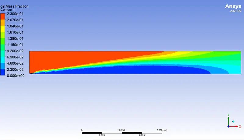
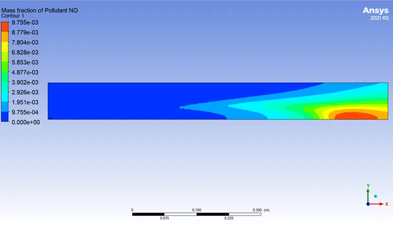
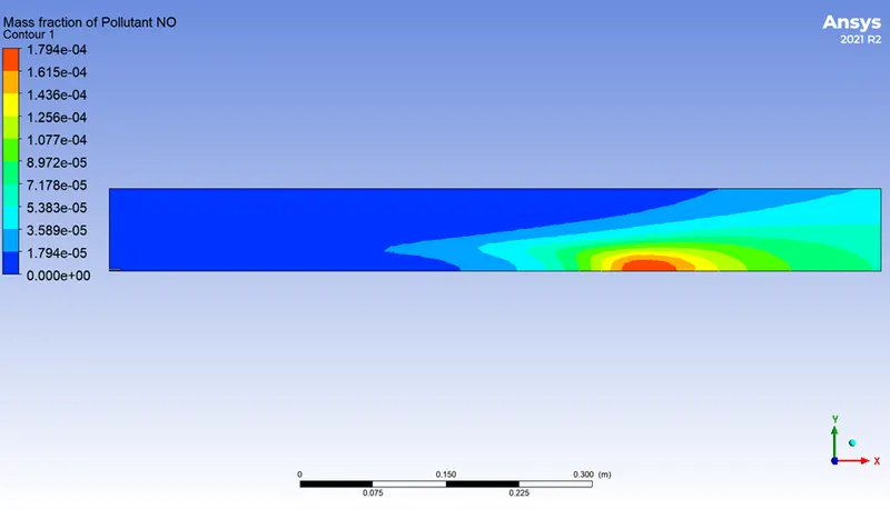
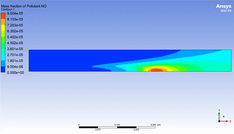
Mass fraction of Pollution NO contour:
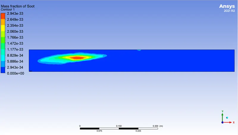
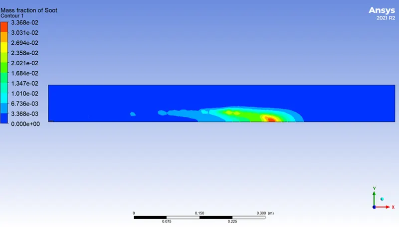
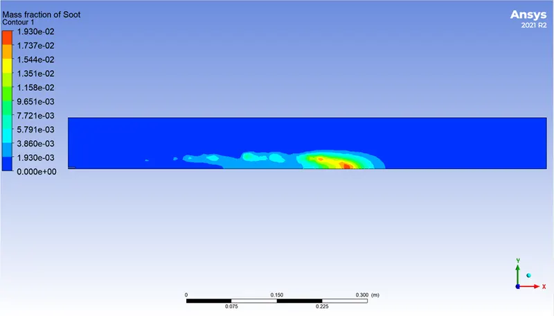
Mass fraction of Soot contour:
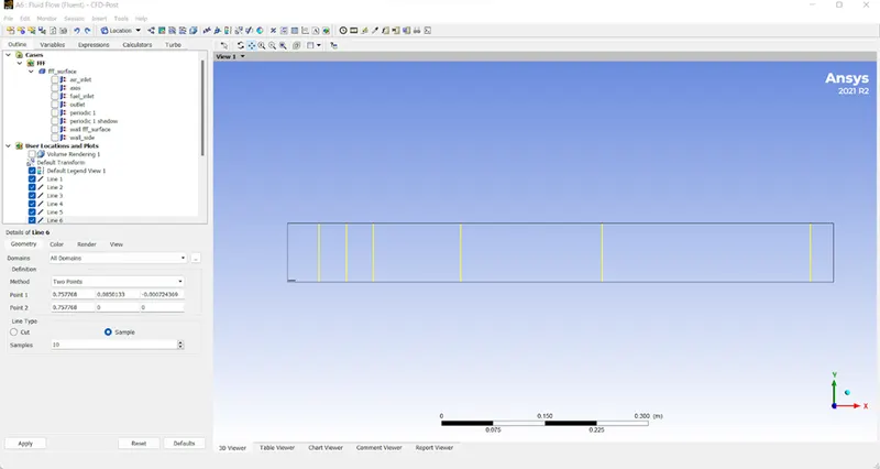
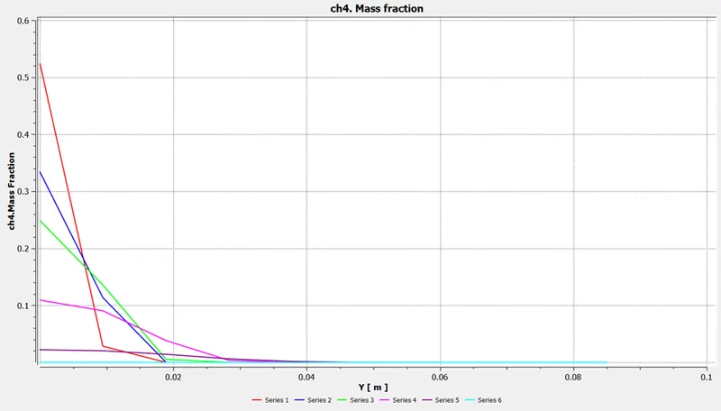
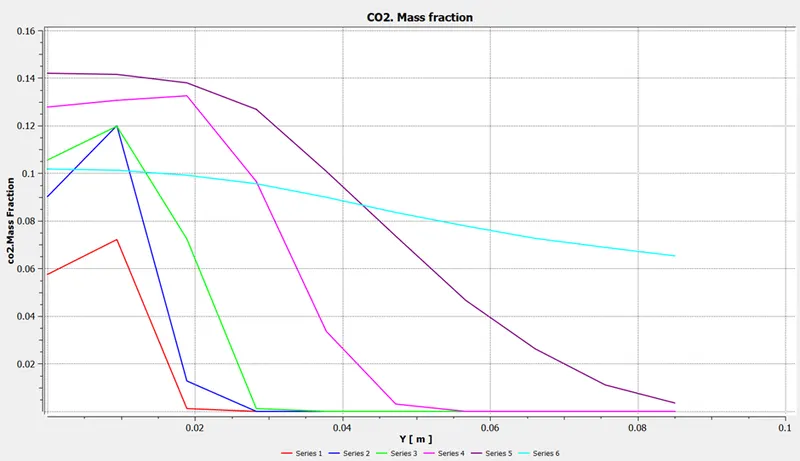
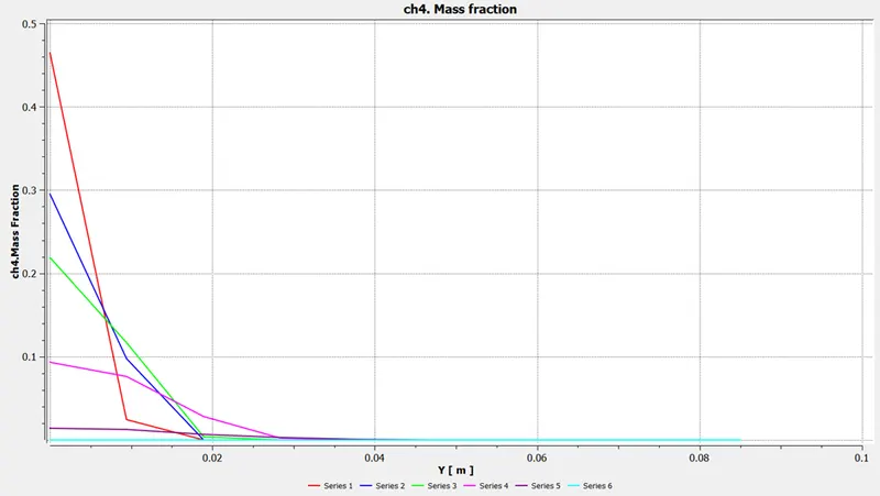
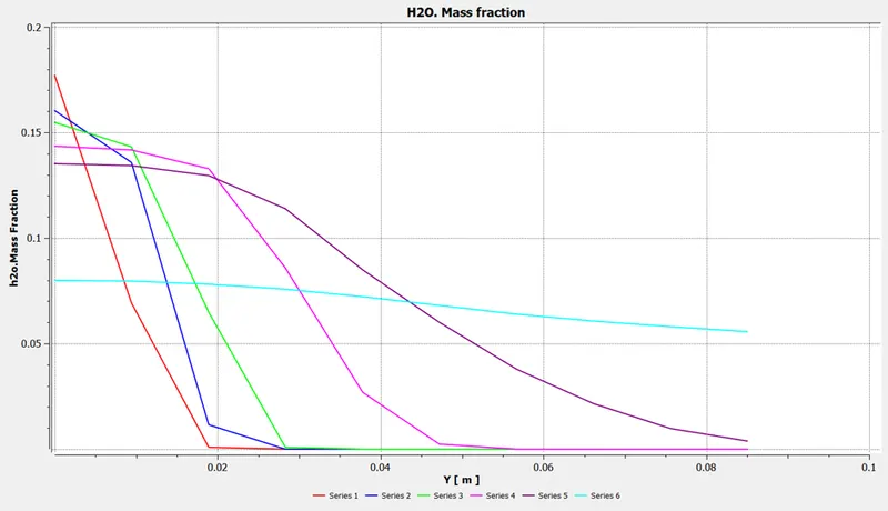
Line plots to create a graph:
Graphs of natural gas:
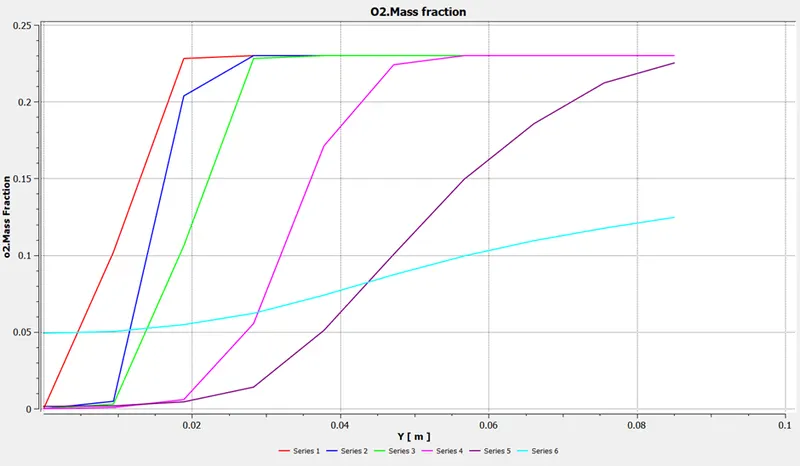
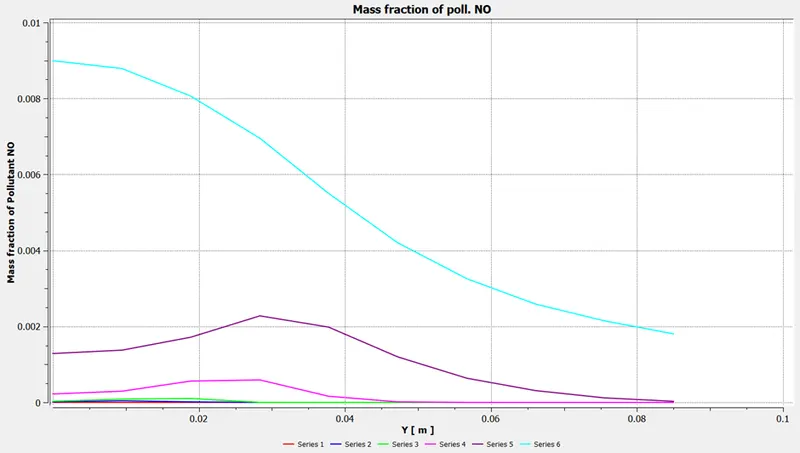
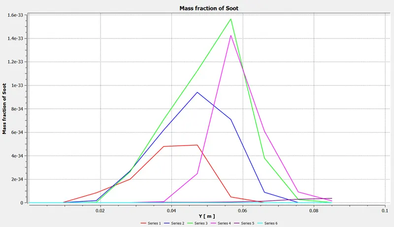
PART II
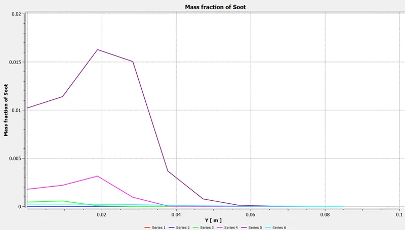
The baseline mesh arrangement demonstrates the proportion of NOx and soot produced by the burner. More NOx is found towards the outflow, and soot production occurs close to the air input. The fuel is combined with water vapor that enters from the same inlet site to reduce NOx and soot formation in the burner.
| [(5-30)% addition of water in fuel] | ||||
| Boundary condition | Temperature | Species mass fraction | ||
| Air inlet | 0.5 m/s | 300 K | O2 | 0.23 |
| fuel inlet | 80 m/s | 300 K | CH4 + H2O | 0.95 + 0.05 |
| Part II | ||
| Cases | (5-30)% of water | Species-Fuel inlet [CH4 + H2O] |
| Case 1 | 10% | 0.90 + 0.10 |
| Case 2 | 20% | 0.80 + 0.20 |
| Case 3 | 30% | 0.70 + 0.30 |
Case 1: 10% of H20 added to CH4
Contour results:
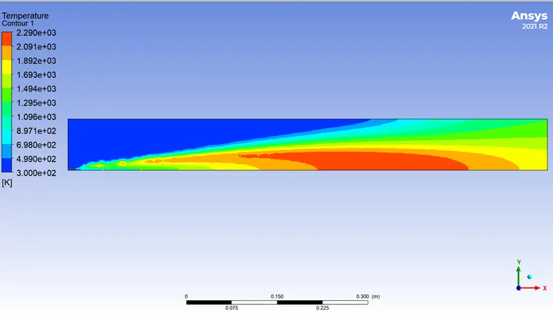
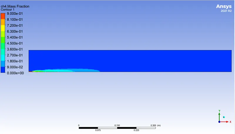
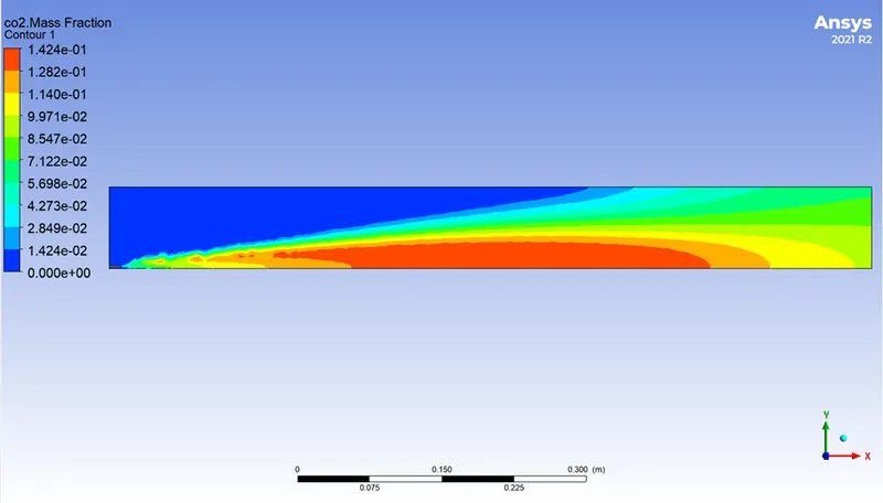
Graphs of natural gas:
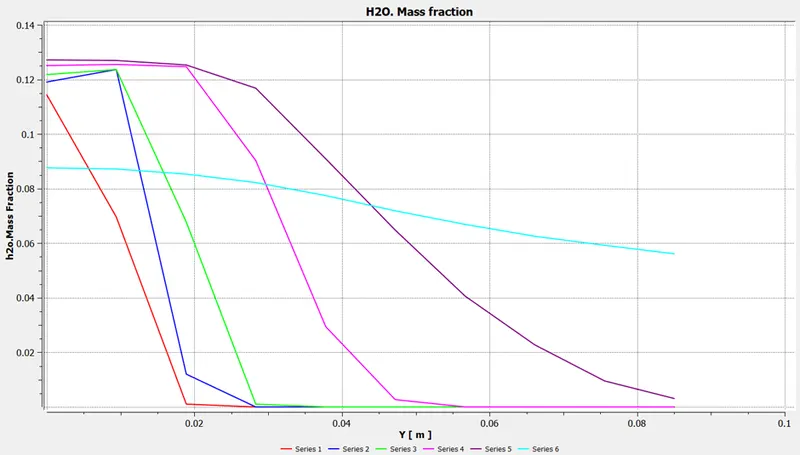
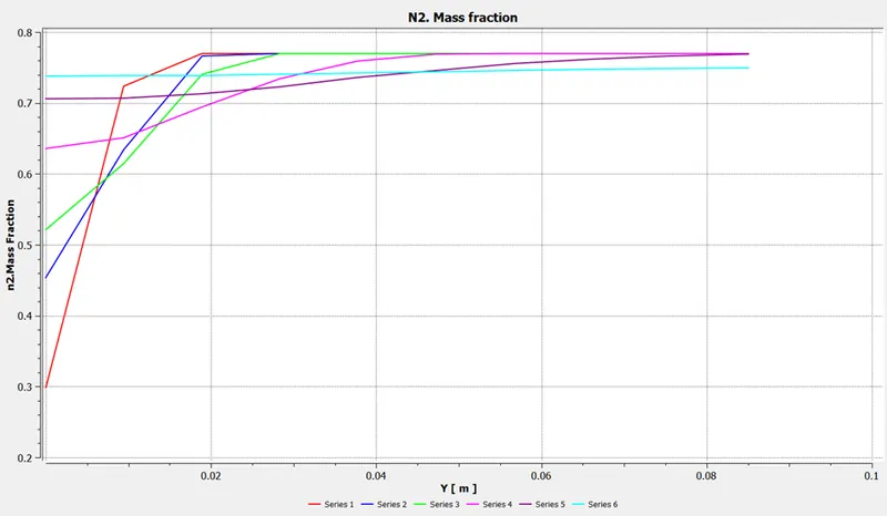
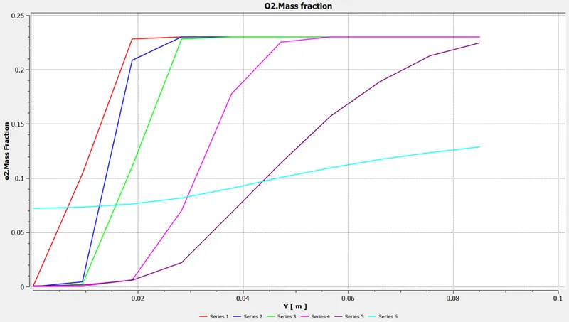
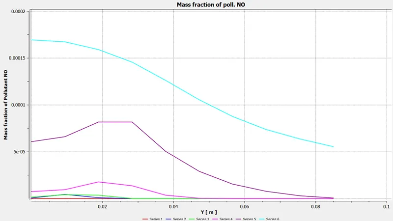
Case 2: 20% of H20 added to CH4
Contour results:
Case 3: 30% of H20 added to CH4
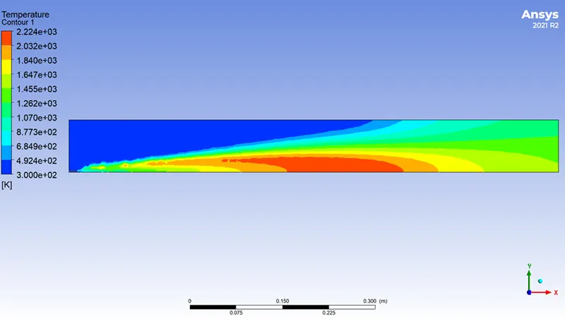
Contour results:
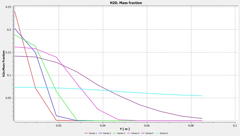
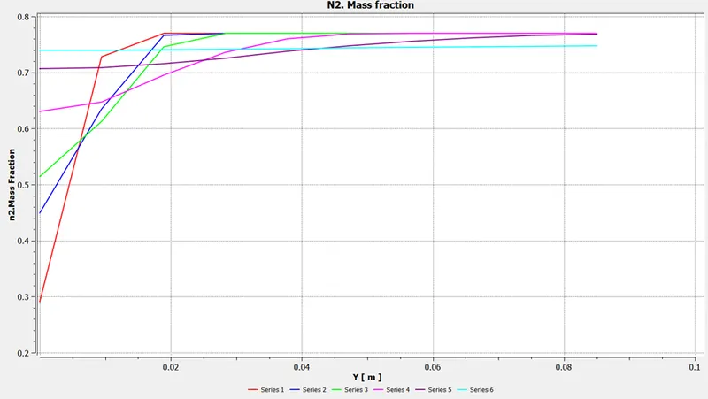
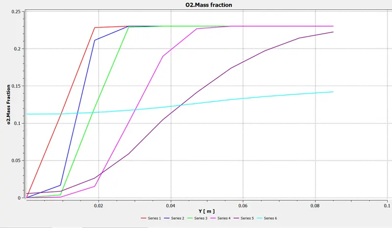
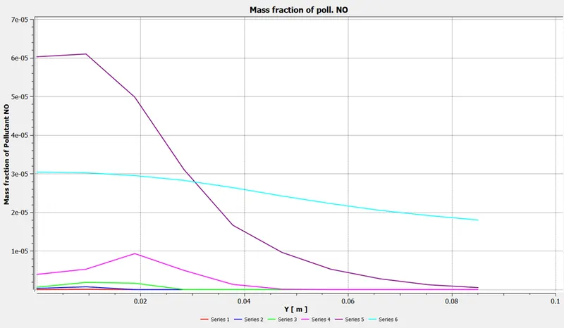
Parametric study:
Results for all cases of the simulation:
The output of design plots,
Conclusion:
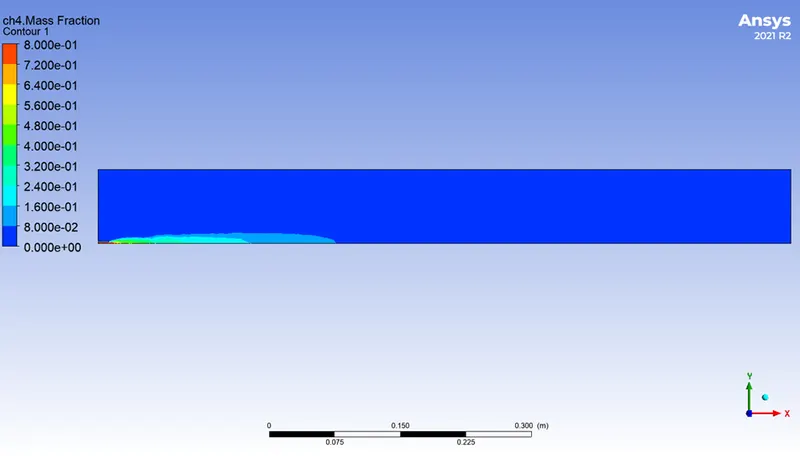
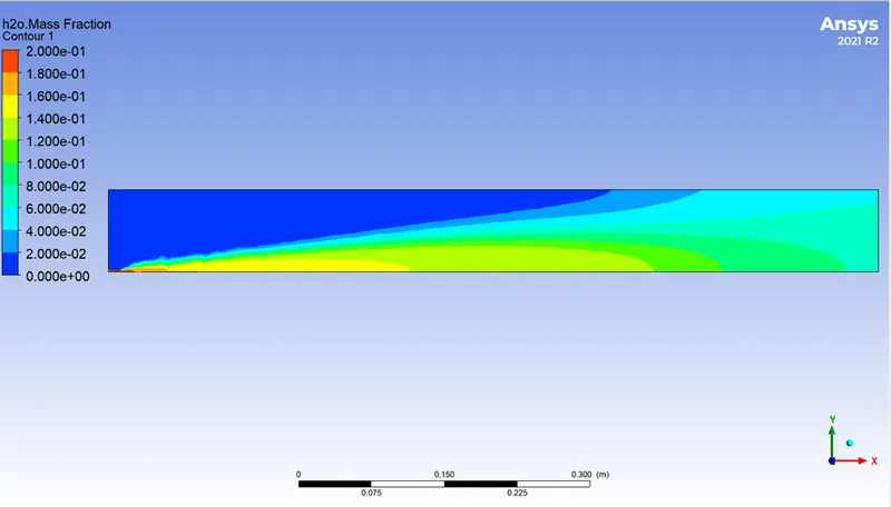
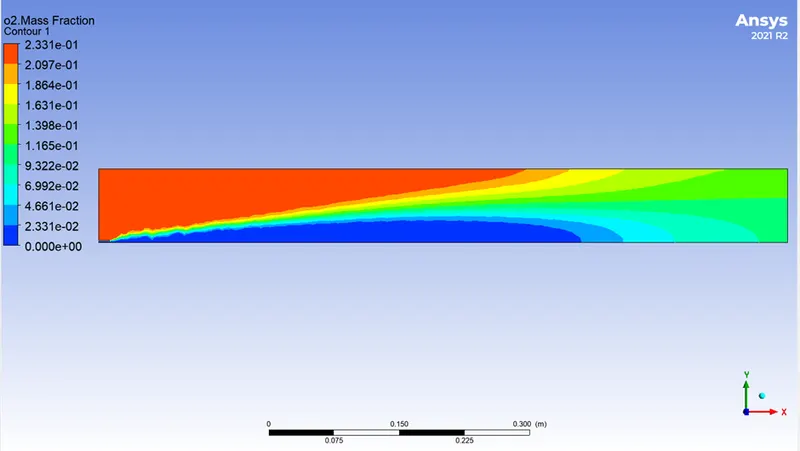
This study examines the mass percentage of products generated during natural gas combustion and soot production. Even while soot can be utilized as a black pigment, it and NOX have a negative impact on the environment. Methods used following treatment can help to decrease soot. In this investigation, we simulated while adding water to the fuel. Although we are unable to tell much about how water entry affects soot generation, the NOx mass fraction is dropping as water content rises. Because burning starts in the middle of the combustor, methane levels decrease starting in the middle, and methane levels decrease of the combustor, methane levels are decreasing as we get closer to the exit