Week 10 - Simulating Combustion of Natural Gas.
AIM
Part I
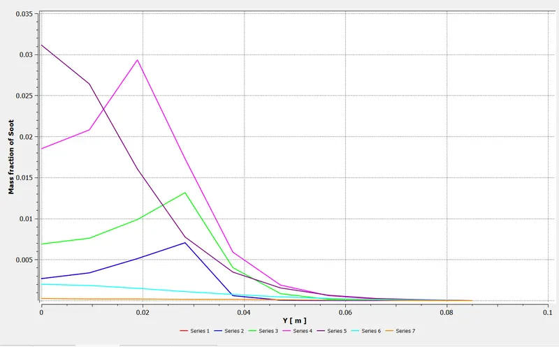
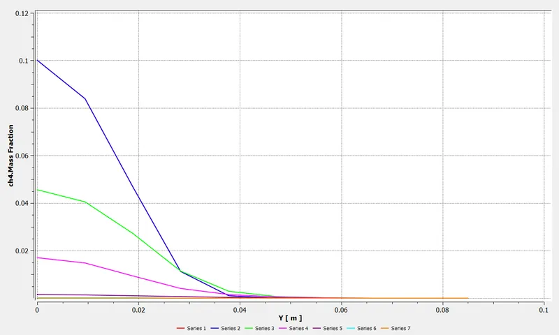
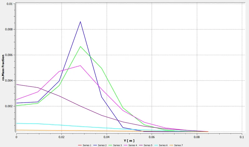
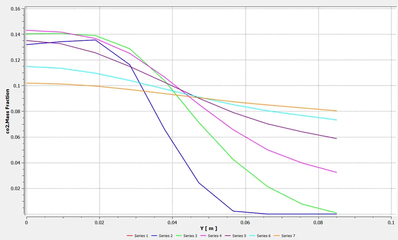
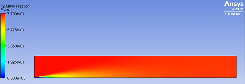
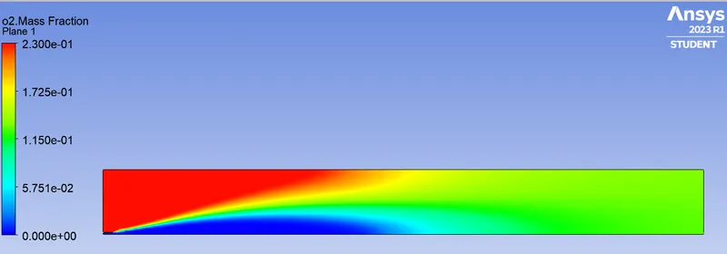
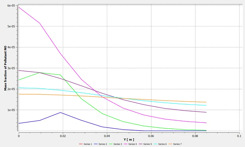
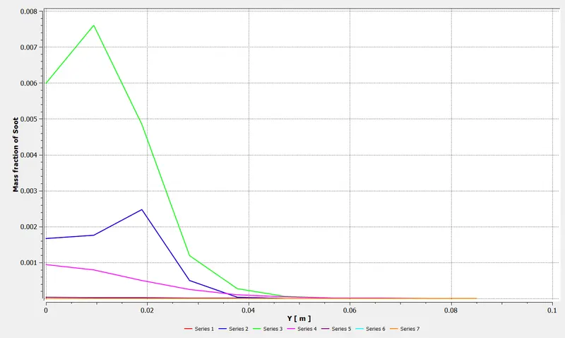
Perform a combustion simulation on the combustor model and plot the variation of the mass fraction of the different species’ in the simulation using line probes at different locations of the combustor. Plot for CO2, H2O, CH4, N2, O2, NOx emissions & Soot formation.
Part II
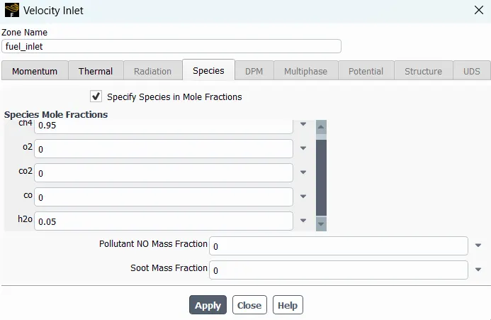
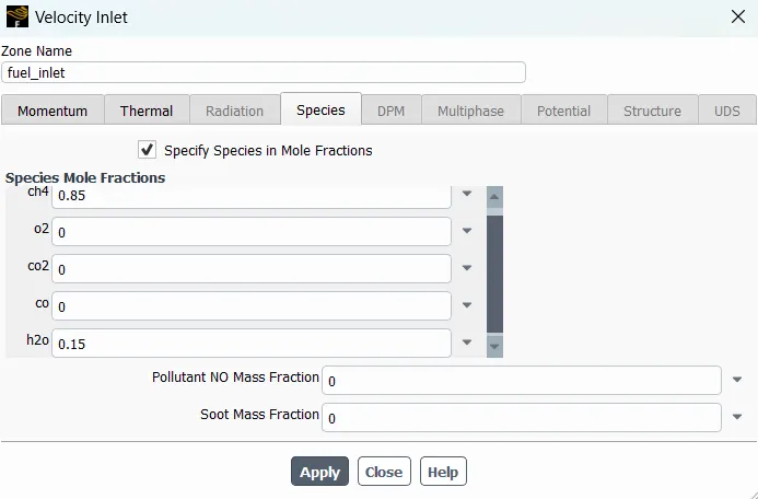
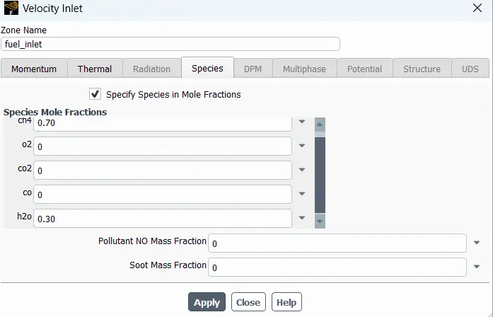
In this part, add the water content in the fuel from 5% to 30% by mole and observe the effect of it on the results.
COMBUSTION & COMBUSTION MODELS
Combustion is a type of chemical reaction which occurs at elevated temperatures causing heat and light generation by forming of oxides. Oxygen is mainly involved in this chemical reaction.
Combustion reaction holds utmost importance because the energy released during combustion is used as the energy source for many engineering applications such as engines, burners etc. It is essential to study the reaction to get important parameters like reaction time, temperature distributions, ignition delay which directly affect the performance and efficiency of the product it is being used for.
MODEL AND APPROACH
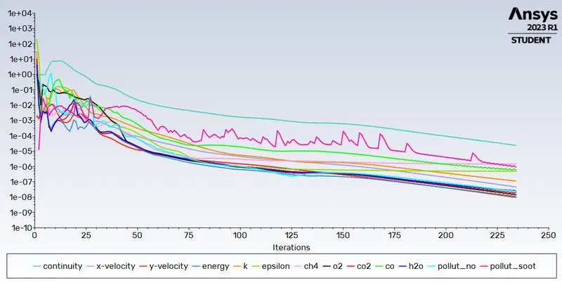
To get these particular results, Eddy dissipation model is being used. In this model the approach to combustion is 'mixing means burning' which means that when the fuel and air gets mixed properly due to turbulence and the k values reach a certain range, the model is said to have achieved a state of combustion. In this method the temperature distribution can be exmained well but ignition delay cannot be solved for using this approach. To solve for other parameters, accurate models incorporating chemical kinetics equations is needed.
GEOMETRY
- Geometry of combustor is imported to the spaceclaim set-up
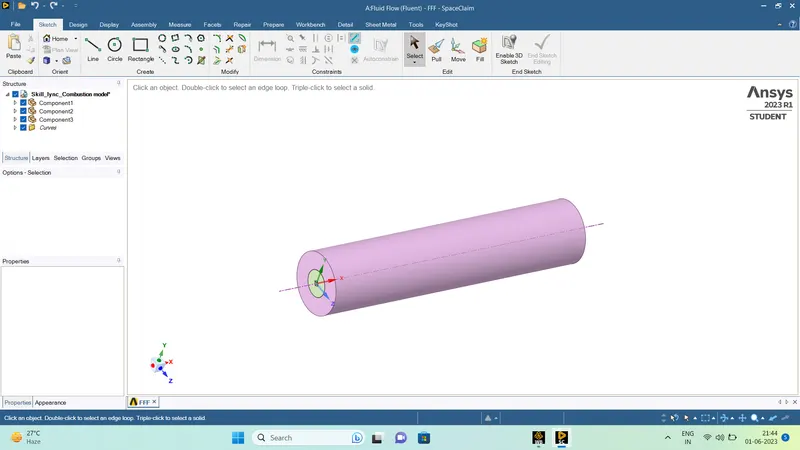
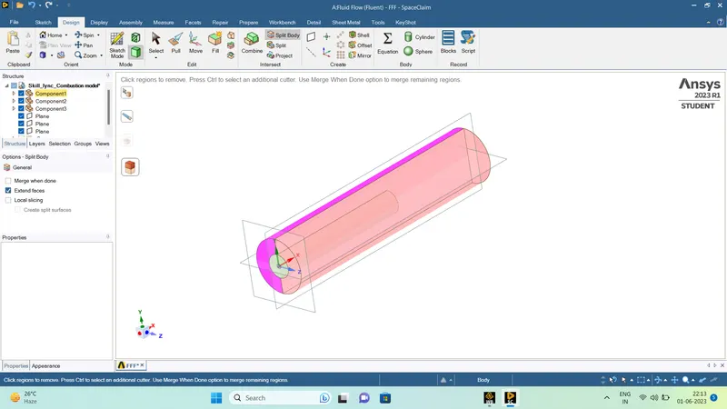
- By using split body command, the bpdy can be split in a quarter portion
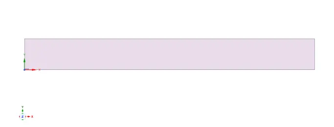
- The surface of the quarter portion is merged and used as geometry for the simulation
MESH
- Named selections for air-inlet, fuel-inlet, Outlet, Wall and Axis are made
- For meshing the 2D geometry, Element size = 2 mm
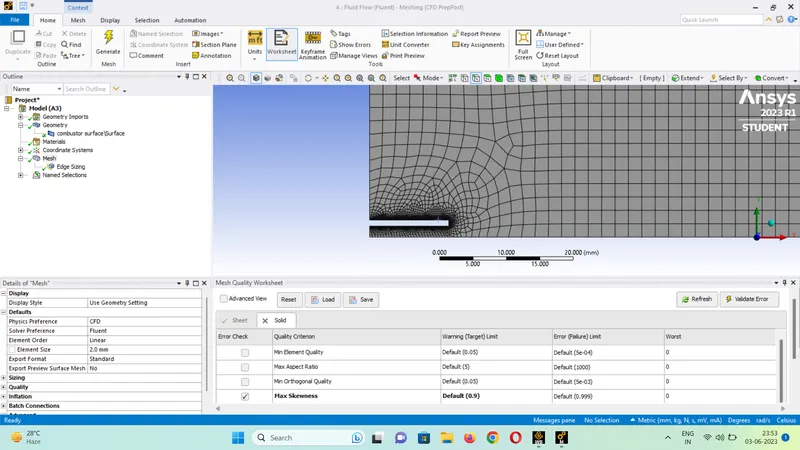
- The edges of fuel inlet are sized to Element size-0.1 mm

SET-UP
The settings used for modeling the simulation :-
Turbulence Model : k-epsilon (standard wall function)
Species : Turned ON
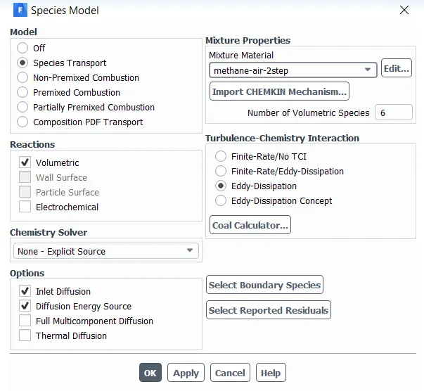
Energy : Turned ON
NOX Model - ON
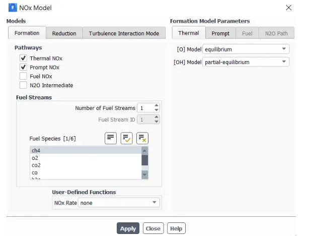
Soot Model - ON
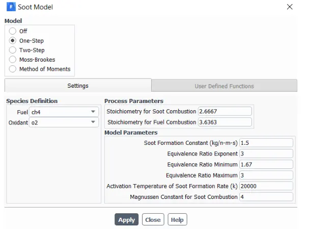
Solver - Pressure Based
Steady, Axisymmetric Problem
Boundary Conditions :-
Air-inlet Velocity - 0.5 m/s
Fuel-inlet velocity - 80 m/s
Materials :-
- Air
- Methane (CH4)
Mass Fraction of air :-
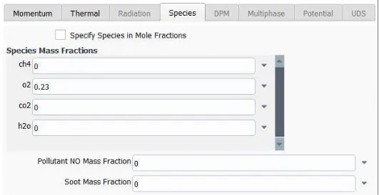
For Part -1
Mass Fraction of fuel :-
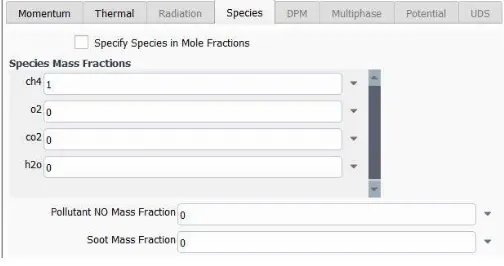
For Part -2
Mass Fraction of fuel :-
5% Water Content by Mole
15% Water Content by Mole
30% Water Content by Mole
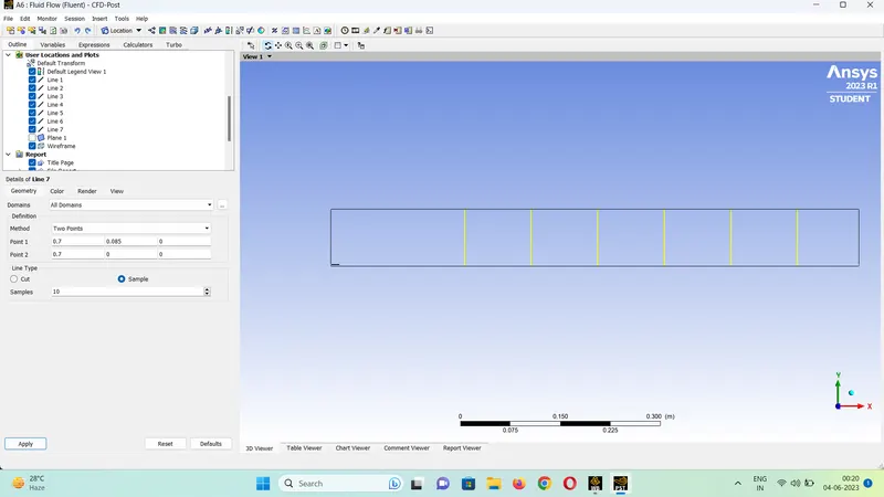
For studying the concentration of different species with different fuel content, line probes are set-up in the post-processing and appropriate concentration charts are created using the same. The line probes are set-up at X= 100 mm, 200 mm, 300mm, 400 mm, 500 mm, 600 mm, 700 mm
RESULTS
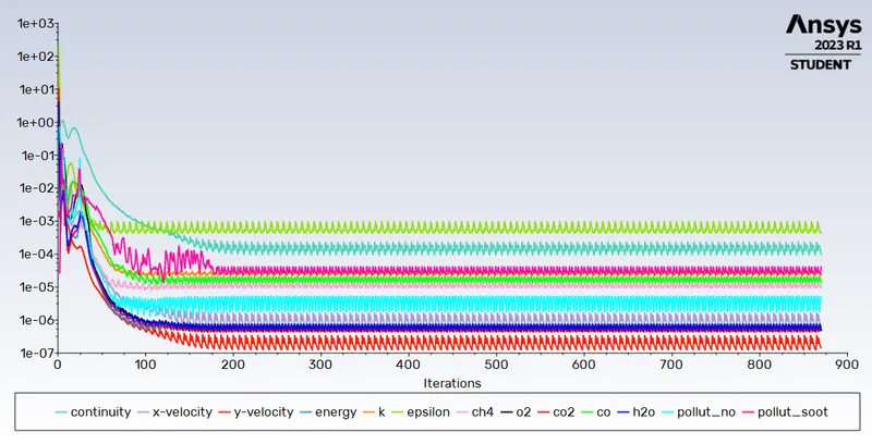
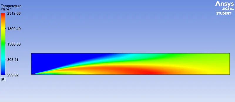
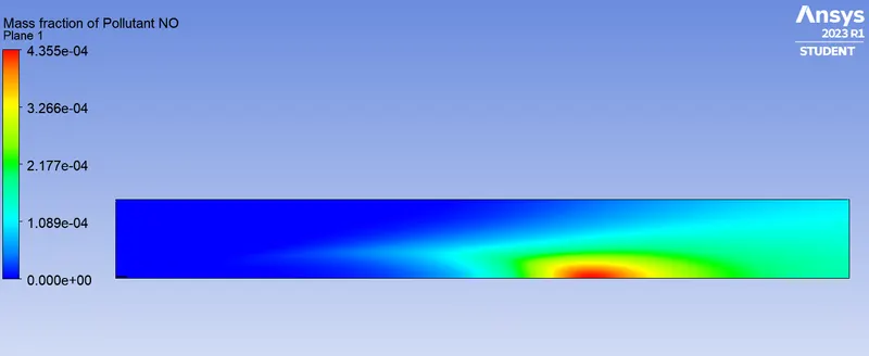
For No water content in Fuel
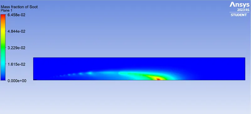
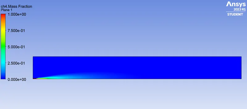
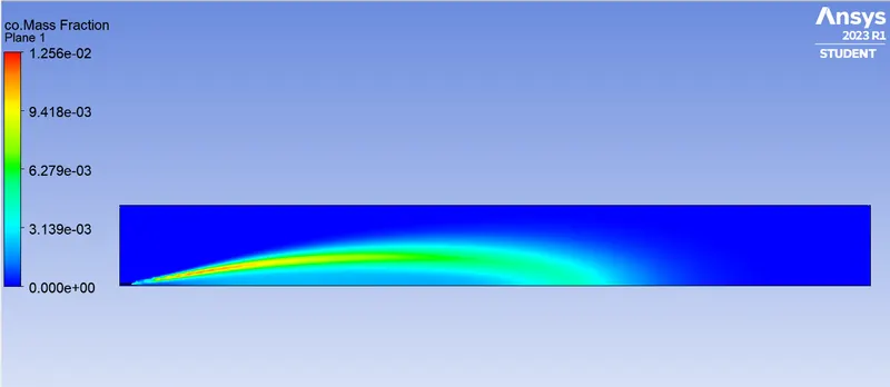
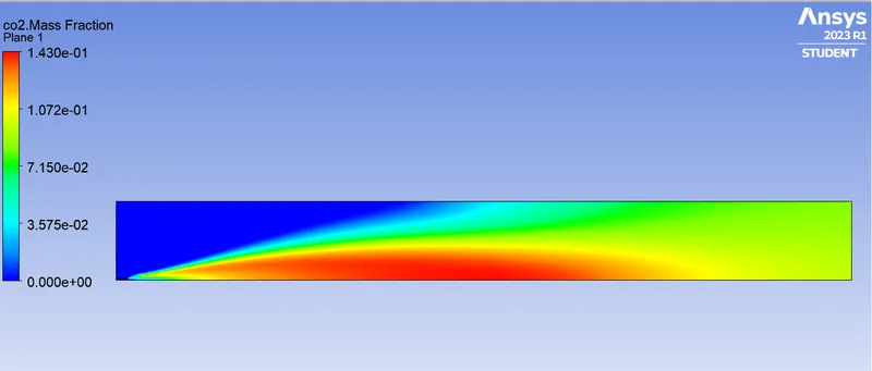
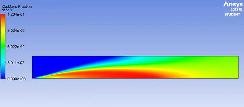
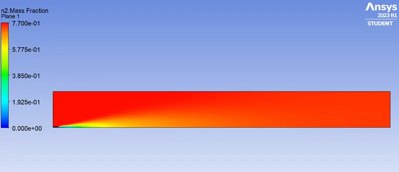
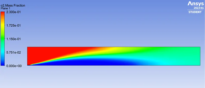
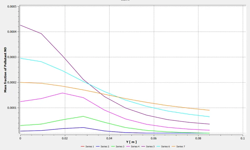
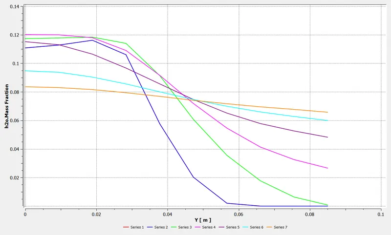
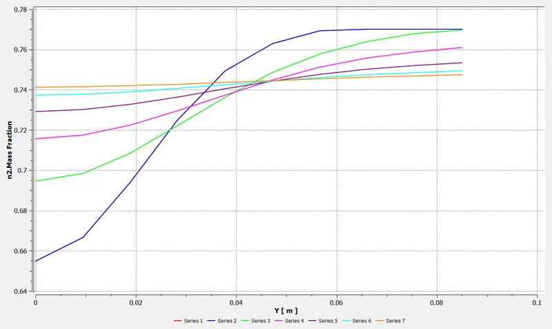
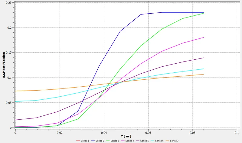
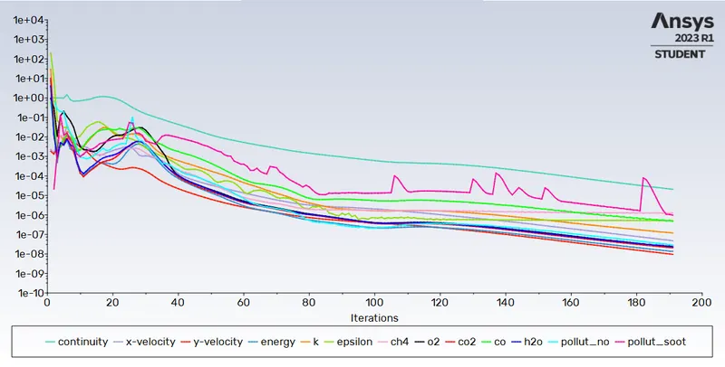
For 5% water content in Fuel
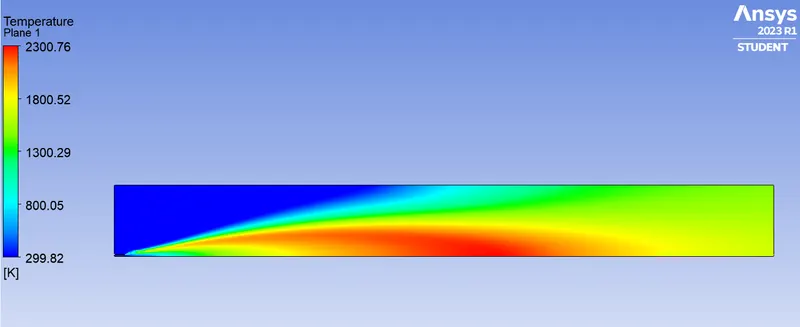
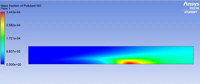
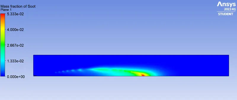
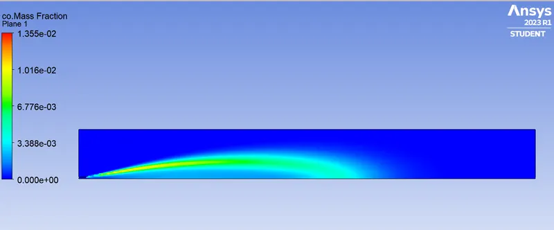
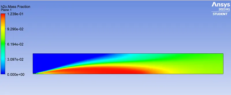
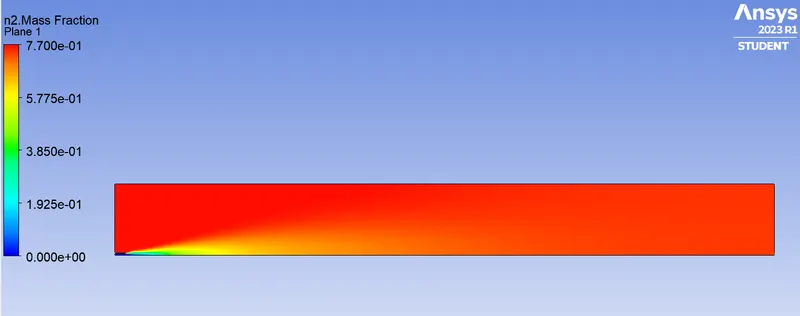
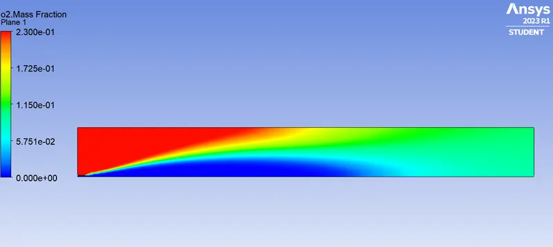
For 15% water content in Fuel
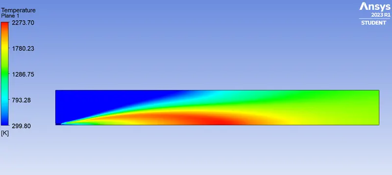
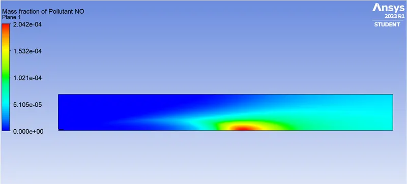
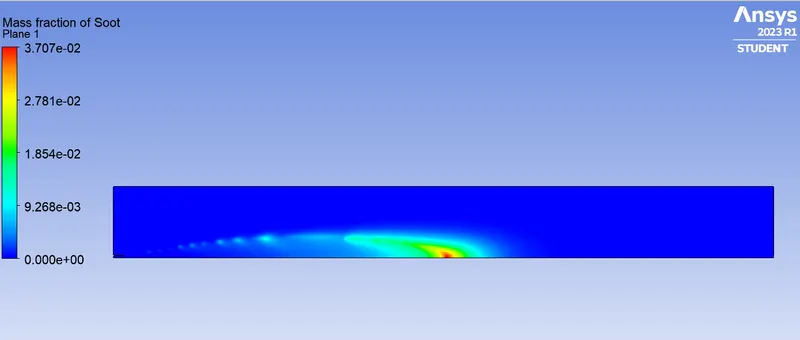
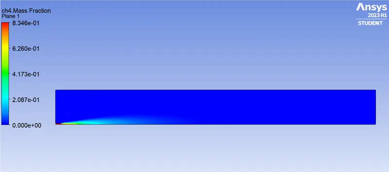
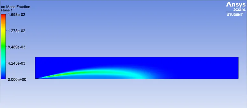
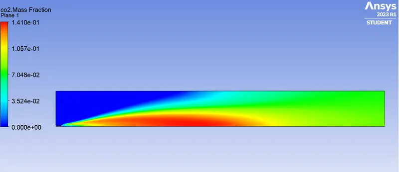
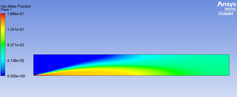
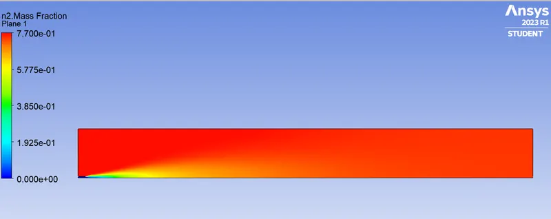
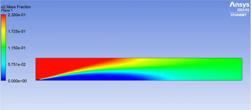
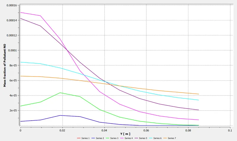
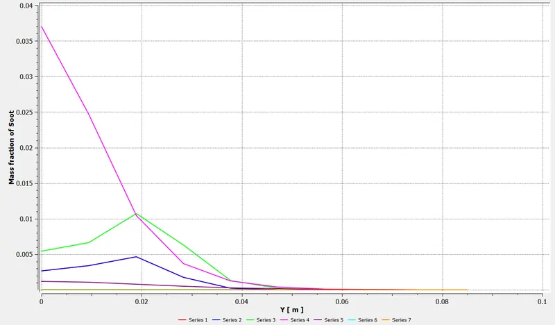
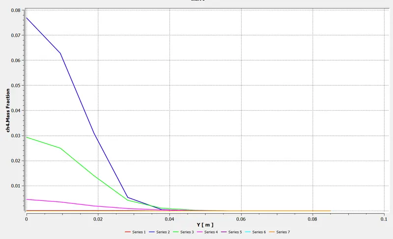
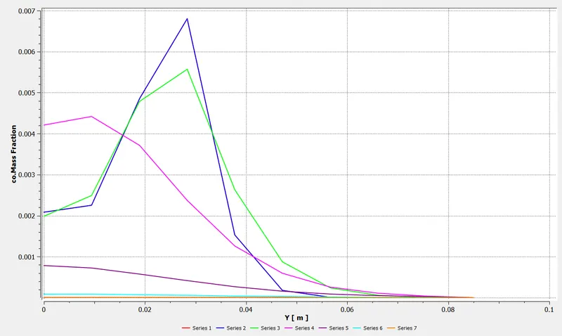
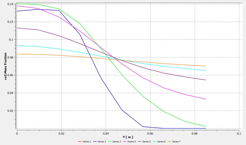
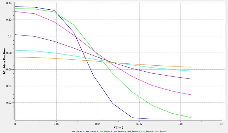
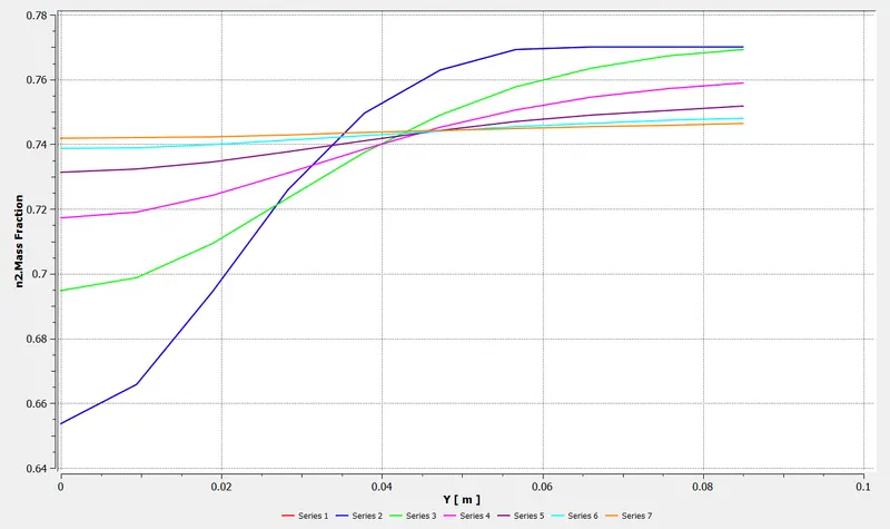
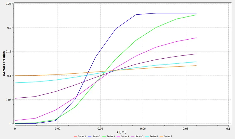
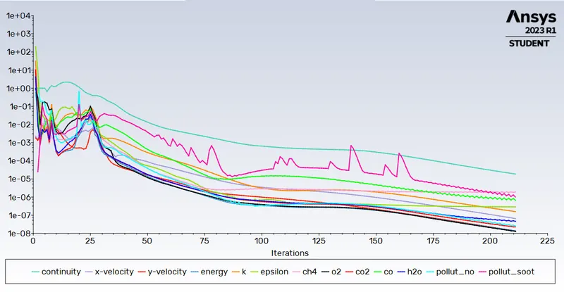
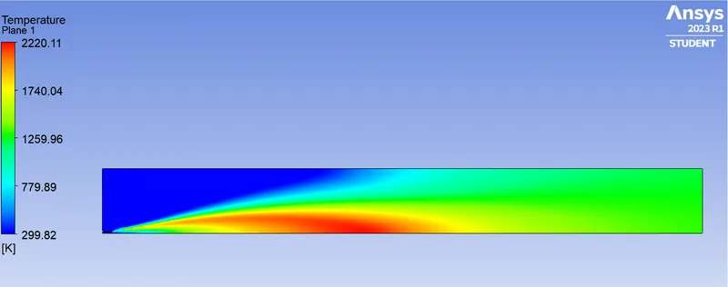
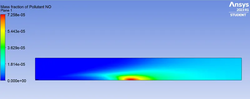
For 30% water content in Fuel
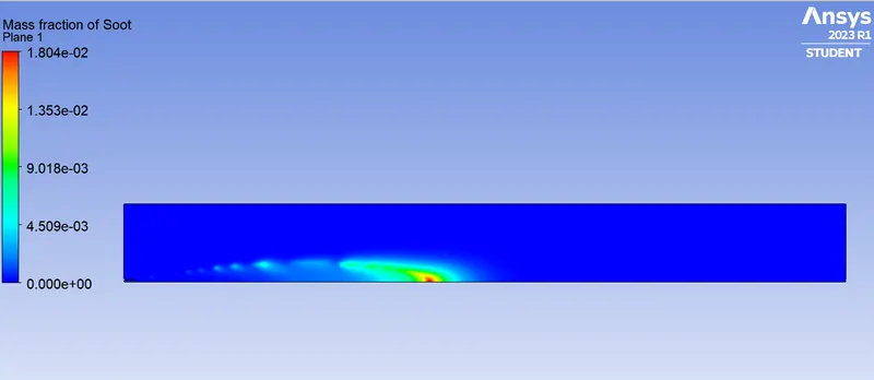
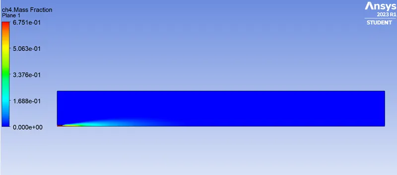
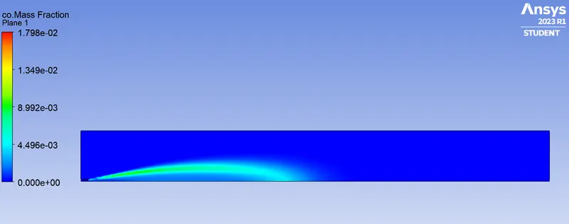
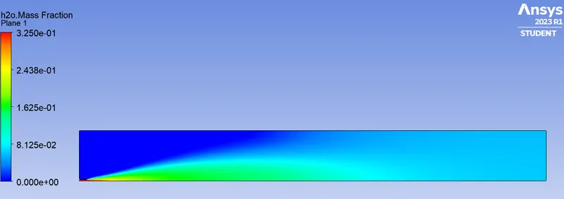
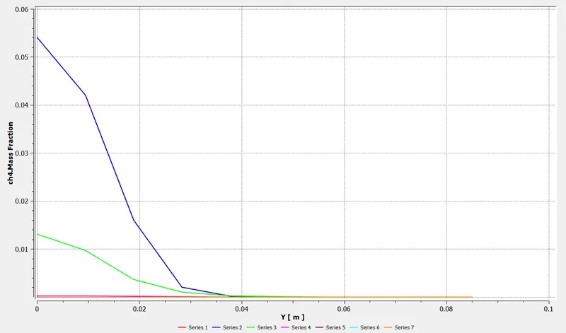
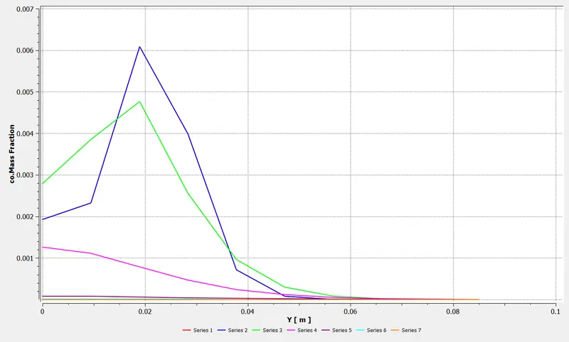
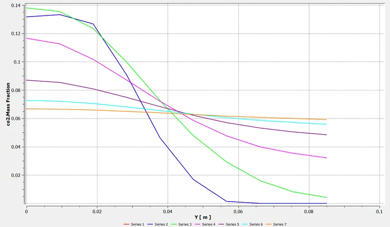
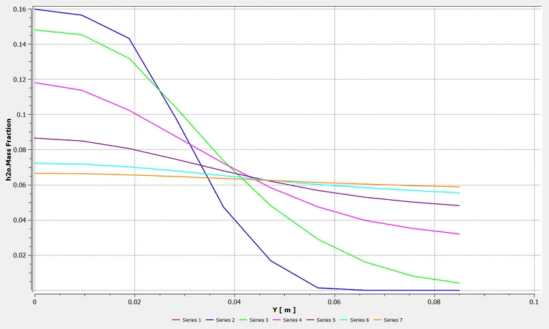
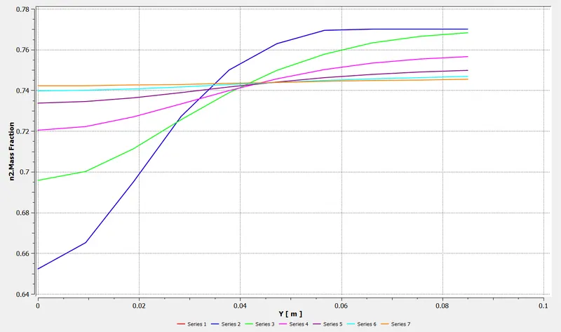
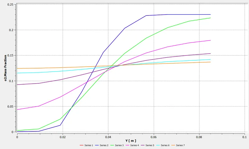
| CH4 Mole Fraction | Water Mole Fraction | Soot Mass Fraction | Nox Mass Fraction |
| 1 | 0 | 0.06 | 0.0004 |
| 0.95 | 0.05 | 0.05 | 0.0003 |
| 0.85 | 0.15 | 0.03 | 0.0002 |
| 0.7 | 0.3 | 0.01 | 0.00007 |
CONCLUSION
- It can be concluded from the above results that as the water content in the fuel is increases, soot and Nox concentrations decrease in the combustor. Soot and Nox are major pollutants and hence the study to keep the concentrations of these poluutants in check is important for minimizing environmental effects and to meet stringent government guidelines. By adding water to the mixture, desired results can be achieved.
- Temperature of the combustor is also decreasing by adding water to the fuel