Week 10 - Simulating Combustion of Natural Gas.
WEEK - 10 HEAT TRANSFER ANALYSIS ON HEAT GENERATING BATTERY
AIM :
To perform the heat transfer analysis using ANSYS -Fluent software for the cylindrical Lithium-Ion Battery with heat generation boundary condition.
Create an enclosure and use air as the wworrking fluid for cooling the battery pack system (4x2). Take air inlet temperature 26˚C and space between the batteries as 2mm.
GIVEN :
Property of the Lithium-ion Batttery
- Nominal Voltage = 3.6V
- Nominal Capacity = 2.2A
- Density = 2722kg/m^3
- Specific Heat = 1200J/kg.K
- Thermal Conductivity = 0.2W/m.K
- Heat Source = 48750 W/m^3 (1.5C discharge rate)
- Size of the battery = 18mm diameter and 65mm height
EXPECTED RESULTS
- Explain why battery cooling is needed and give a brief description about various techniques for battery cooling.
- Perform mesh independent study for any one case and based on your judgement use the more suitable model or further cases.
- Run the simulation by varying the velocity of air as 3, 5 and 10m/s and discuss the results.
- Find out the maximum temperature and heat transfer coefficient obtained by the battery..
- Based on the results and on your judgement, select one case(3, 5 or 10m/s) and vary the space between the batteries as 2, 4 and 6mm, then discuss the results.
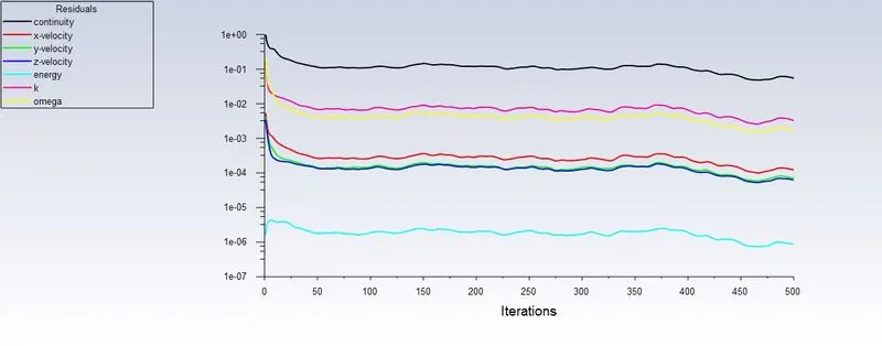
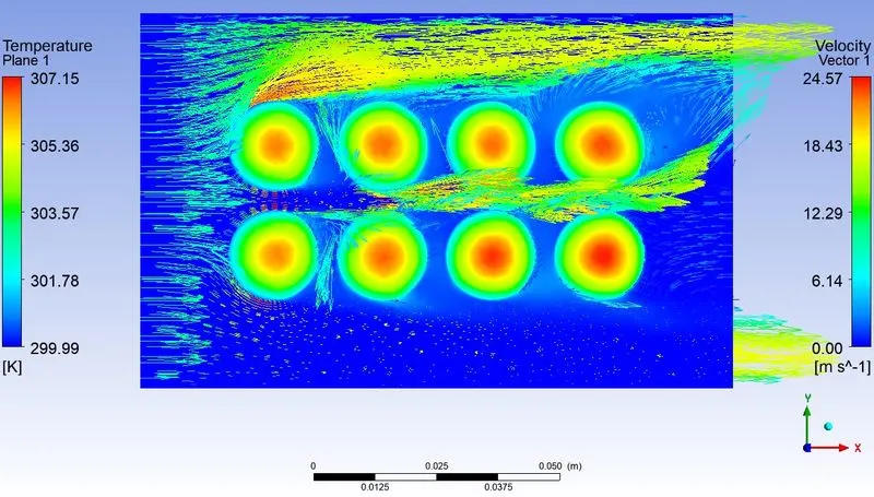
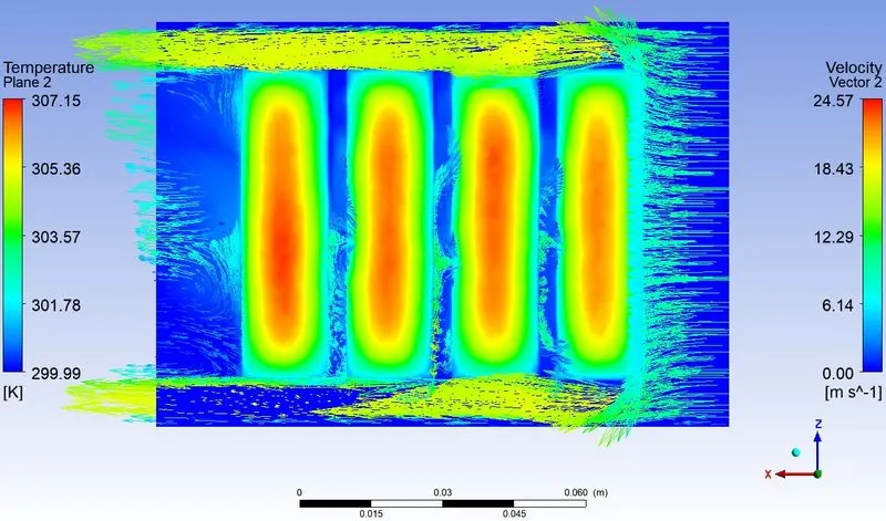
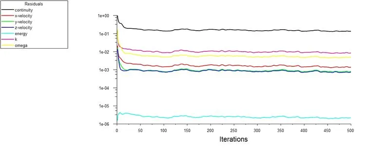
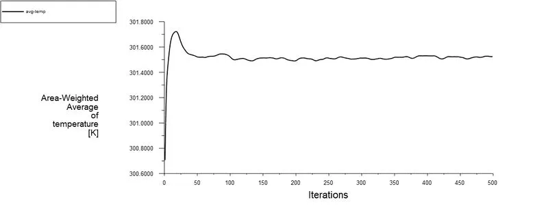
- Prove that the simulation has achieved convergence with appropriate images and plots (Velocity and temperature contour plots on the cut planes).
- Create the animation to observe the temperature distribution and velocity vector.
- Summarize the results in tabulation / graphical form.
- State the inferences based on the results.
LEARNING OBJECTIVE :
- Why electric vehicle?
- Battery
- Thermal Runway
- Battery Thermal Management
- Flow Simulation
Why electric vehicle?
Transport is a fundamental requirement of modern life, but the traditional combustion engine is quickly becoming outdated. Petrol or diesel vehicles are highly polluting and are being quickly replaced by fully electric vehicles. Fully electric vehicles (EV) have zero tailpipe emissions and are much better for the environment.
- Low running cost
- Low maintenance cost
- Zero tailpipe emissions
- Convience of charging at home
- No noise pollution
Battery
A battery is a source of electric power consisting of one or more electrochemical cells with external connections for powering electrical devices. When a battery is supplying power, its positive terminal is the cathode and its negative terminal is the anode. The terminal marked negative is the source of electrons that will flow through an external electric circuit to the positive terminal. When a battery is connected to an external electric load, a redox reaction converts high-energy reactants to lower-energy products, and the free-energy difference is delivered to the external circuit as electrical energy. Historically the term "battery" specifically referred to a device composed of multiple cells; however, the usage has evolved to include devices composed of a single cell.
Primary (single-use or "disposable") batteries are used once and discarded, as the electrode materials are irreversibly changed during discharge; a common example is the alkaline battery used for flashlights and a multitude of portable electronic devices. Secondary (rechargeable) batteries can be discharged and recharged multiple times using an applied electric current; the original composition of the electrodes can be restored by reverse current. Examples include the lead-acid batteries used in vehicles and lithium-ion batteries used for portable electronics such as laptops and mobile phones.
Batteries come in many shapes and sizes, from miniature cells used to power hearing aids and wristwatches to, at the largest extreme, huge battery banks the size of rooms that provide standby or emergency power for telephone exchanges and computer data centres. Batteries have much lower specific energy (energy per unit mass) than common fuels such as gasoline. In automobiles, this is somewhat offset by the higher efficiency of electric motors in converting electrical energy to mechanical work, compared to combustion engines.
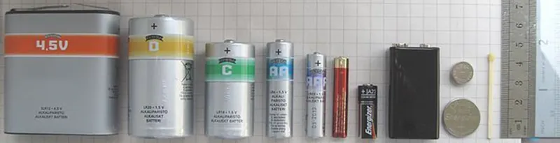
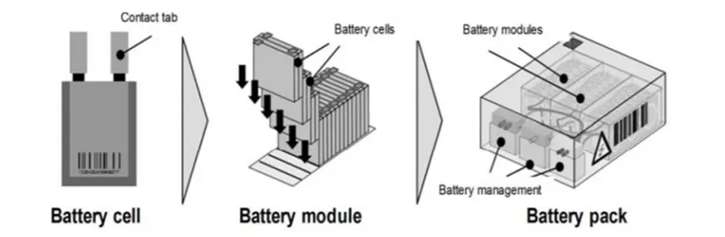
Batteries are classified into primary and secondary forms:
Primary batteries are designed to be used until exhausted of energy then discarded. Their chemical reactions are generally not reversible, so they cannot be recharged. When the supply of reactants in the battery is exhausted, the battery stops producing current and is useless.
Secondary batteries can be recharged; that is, they can have their chemical reactions reversed by applying electric current to the cell. This regenerates the original chemical reactants, so they can be used, recharged, and used again multiple times. 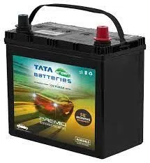
Thermal Runaway
Thermal runaway describes a process that is accelerated by increased temperature, in turn releasing energy that further increases temperature. Thermal runaway occurs in situations where an increase in temperature changes the conditions in a way that causes a further increase in temperature, often leading to a destructive result. It is a kind of uncontrolled positive feedback.
In chemistry (and chemical engineering), thermal runaway is associated with strongly exothermic reactions that are accelerated by temperature rise.
In electrical engineering, thermal runaway is typically associated with increased current flow and power dissipation.
When handled improperly, or if manufactured defectively, some rechargeable batteries can experience thermal runaway resulting in overheating. Sealed cells will sometimes explode violently if safety vents are overwhelmed or non-functional. Especially prone to thermal runaway are lithium-ion batteries, most markedly in the form of the lithium polymer battery.
In 2006, batteries from Apple, HP, Toshiba, Lenovo, Dell and other notebook manufacturers were recalled because of fire and explosions. The Pipeline and Hazardous Materials Safety Administration (PHMSA) of the U.S. Department of Transportation has established regulations regarding the carrying of certain types of batteries on airplanes because of their instability in certain situations. This action was partially inspired by a cargo bay fire on a UPS airplane. One of the possible solutions is in using safer and less reactive anode (lithium titanates) and cathode (lithium iron phosphate) materials — thereby avoiding the cobalt electrodes in many lithium rechargeable cells — together with non-flammable electrolytes based on ionic liquids.
What's C Rate?
The C-rate is a unit to declare a current value which is used for estimating and / or designating the expected effective time of battery under variable charge / discharge condition.
Battery Thermal Management
The battery pack for safety, performance (both power and capacity) and lifespan reasons should be stored in a controlled surrounding where the temperature is controlled and there is no risk of thermal runaway. According to a foundational research (Pesaran, 2001), the BTMS should be equipped with four essential functions to ensure the right operation conditions of the battery pack:
1. Cooling
Due to inefficiency, battery cells will not only generate electricity but also heat. This heat should be moved from the battery pack when battery temperature reaches the optimum temperature or even in advance. Thus, a cooling function is required in BTMS.
2. Heating
In cold climates, battery pack temperature probably falls below the lower temperature limit. Hence, a heating function, such as PTC heater, is required to assist the battery pack to reach the proper temperature range in a shorter time.
3. Insulation
In extreme cold or hot weather, the temperature difference between the inside and outside of the battery pack is much larger than that in mild weather. Battery temperature will thus fall (cold) or rise (hot) sooner out of the proper temperature range. To prevent this, good insulation can slow down the falling or rising of battery temperature, especially when the vehicle is parked outdoors.
4. Ventilation
Ventilation is required to exhaust the hazardous gases within battery pack. In some systems, such as air systems, this function is combined with cooling and heating functions.
What Information is needed to Design a BTMS?
- Acceptable temperature range for cell components at all times, i.e., active material, binders, separators, electrolyte, etc.
- Acceptable temperature difference within cells and from cell to cell, depending on the chemistry and management system
- Maximum and minimum temperature limits for life specifications, performance ratings, and safety considerations
- Thermo-physical properties of cells or components (density, specific heat, directional thermal conductivities)
- Heat generation rate under average and aggressive drive profiles and loads for the specific electric drive
- Heat rejection rate depending on thermal management strategy
- Fluid heat transfer coefficients or sink conductance
- Cooling fluid flow rate and sink temperature
- Configurations and dimensions of cells and proposed BTMS
- Parasitic power needed to push fluids/cooling through BTMS
Different Battery Cooling Methods Used in BTMS
- To adapt to EVs, BTMS must ensure features such as high performance, simplicity, low weight, reduced cost, low use of parasitic power and fast packaging, and easy maintenance
- Two types of battery cooling systems (BCS) are common which are external or internal. Many researchers and industries have been developing BCSs
- External Battery cooling systems (EBCS) are classified into several different ways
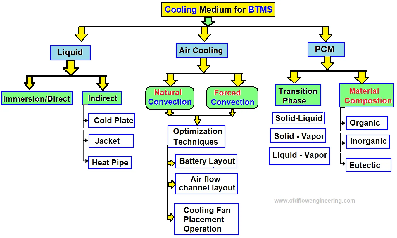
- Battery cooling can be categorized based on the method or technique.
- Liquid or gas cooling: plate type or use of mini-channel)
- Heat pipe
- Phase Change Material (PCM)
Air Cooling
- Air is easily available for cooling purposes and it is widely used in many industries. However, the air is not an effective coolant because of its lower heat capacity and low thermal conductivity
- Due to low maintenance of costs, the following type of air cooling system is popular in some automobile industries like Toyota Prius and Nissan Leaf
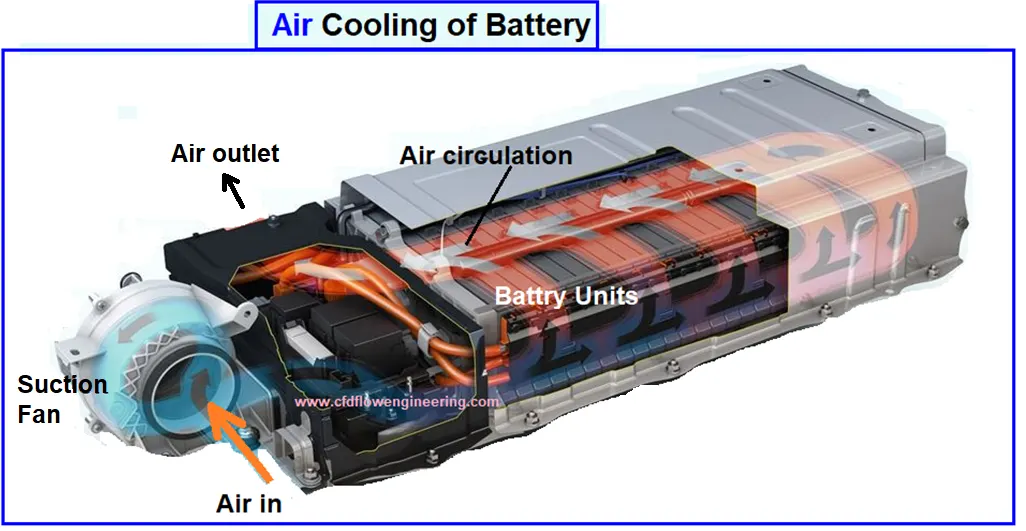
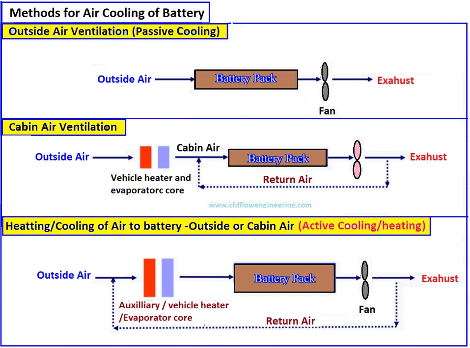
- The cooling is possible either by forced convection (active cooling) mode and natural convection (passive cooling) mode
- Natural convection cooling is suitable only for low-density batteries, and typically blowers/fans can be used to enhance the convection heat transfer rate
- When air is used for cooling of battery modules arranged in series, the middle and rear portion of batteries are at high temperature to the low heat capacity of air. The temperature of the battery pack near the outlet is very high and the temperature distribution is highly non-uniform. To cool effectively, we need to increase the flow rate and turbulence of airflow.
- CFD study of different battery modules can be carried out for different configurations of airflow rates and electric vehicles
Air Cooling Battery Pack in EVs
The following are popular battery pacts with air cooling in electrical vehicles
- Honda Insight
- Honda FitEV
- Hyundai IONIQ
- Nissan e-NV 200
- Nissan Leaf
- Renault Zoe
- Toyota Prius Prime
Liquid cooling of Battery
- Liquid coolants have a high convective heat removal rate due to higher density and heat capacity compared to air
- A liquid cooling system is more compact than an air system. We can save up to 40% of separate power compared to the fans required for air cooling.
- Moreover, liquid cooling can reduce the noise level. However, the complexity of the liquid cooling system and its leakage potential can be defined into direct and indirect cooling.
Indirect liquid cooling
- Water has been an effective coolant for several industrial applications But the main challenge is the short-circuited potential for direct cooling of batteries
- To avoid the short-circuit issue, indirect methods are effective to avoid electrical conduction with cells while maintaining high thermal diffusion
- The addition of electrical resistance may resist thermal diffusion. But its effects on cooling is not significant.
- Some EV manufacturers such as General Motors, and Tesla are using indirect cooling in their cars. General Motor used cold plates between each prismatic cell. The cold plates have several micro-channels for convective heat removal from batteries.
- Tesla has used wavy tubes placed between cylindrical cells. Thermally conductive and electrically insulated material is used to fill the gaps between the battery cells and cooling ducts.
- The wavy tubes may not be effective for cooling because of the small heat transfer contact area, it is safer from the mechanical and electrical point of view. All the connections of coolants are kept outside of the enclosure to avoid the leakage of coolant.
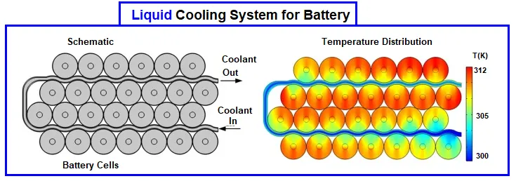
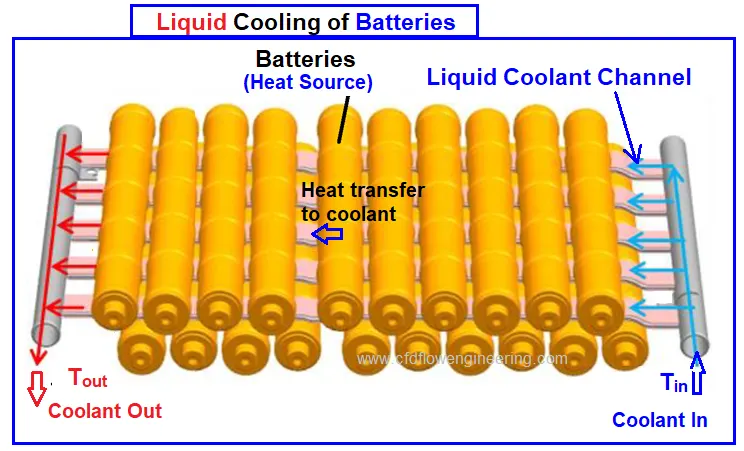
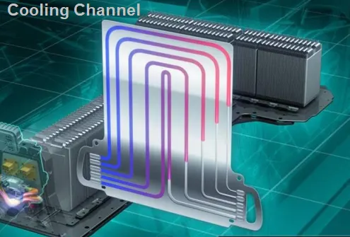
- Liquid cooling of batteries is shown below and heat transfer takes place from the cells to cooling channels
- The design strategy of thermal management system for battery modules, controller, and electric motor
Chevrolet Cooling System
- This consists of a large number of micro-channels embedded in the metal plates to carry out a coolant
- The plate is placed between two battery sets to remove the heat
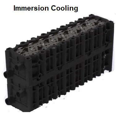
Direct liquid cooling (Immersion)
- Direct cooling is also called immersion cooling, covers the entire surface of the cell and cools it uniformly
- Immersion cooling removes hot or cold spots in the cell and significantly improves the performance of the cell.
- Ideal coolant mush be dielectric with minimum viscosity and high thermal conductivity and thermal capacity
- Immersion cooling is widely used for data center servers and high-power electronics devices
- BTMS for this method is not suitable for most mass-produced EV due to high cost and safety concerns
- Immersion cooling is useful for batteries of high-performing EVs and EV racing. The fluid has a boiling point between 60 – 80 °C to prevent overheating of the cells and avoid thermal runaway. Modular type containers are used for the cells where they can be submerged in the liquid
Liquid Cooling Battery Pack in EVs
The following are popular battery pacts with liquid cooling in electrical vehicles
- Audi R8 e-Tron
- Ford Focus
- GM Chevrolet Bolt and Chevrolet Volt
- Tesla Model X, Model S, Model 3
- Toyota –iQ
- Volvo XC90 T8
Phase change Material (PCM) Cooling
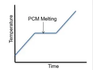
- The phase change material absorbs heat significantly due to high latent heat during battery discharge
- The PCMs have been used for thermal management have a melting point in the optimum performing range of lithium cells. The cell temperature needs to remain for a long time.
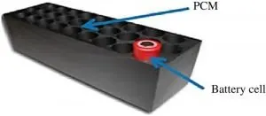
- PCM as paraffin has a melting point in the range of 32-38°C which is mixed with graphite flakes to improve thermal conductivity
- The graphite flakes will also create a semi-matrix block which will contain the paraffin particles. When the paraffin melts, it stays within this matrix and the whole composition remains as the solid form
- The basic equation for phase change material (PCM): V*ρ*L = P*t, where
V = Volume of PCM in cell (m3)
ρ = Density of PCM in cell (kg/m3)
L = Latent heat of fusion of PCM (per kg)
P = Power absorbed (Watt)
t = Time of power absorption (seconds)
- The advantage of solid PCM is that they also act as shields, in case one cell enters a thermal runaway
- Classification of PCM materials for battery cooling is given below
- Select the phase change material which can maintain the temperature of cell 25-35 °C
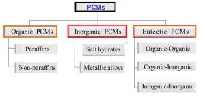
- Multiphase modeling needs to be considered for phase change materials during the cooling of batteries
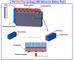
Heat Pipe
- Heat pipes have been considered versatile in many industrial applications for their efficient cooling and
thermal management - Similar to the passive cooling method of PCM, applying the heat pipes to cool or remove heat energy from the battery provides efficient
heat transfer t low power consumption - In this mechanism, heat is transferred through latent heat of vaporization (phase change) from the evaporator to the condense
- The working fluid can be passively transported back to the evaporator by capillary pressures it is developed
within a porous wick lining. Operating in this situation the heat is continuously absorbed and released.
Comparison of Cooling Methods
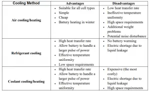
- Commonly used cooling methods are compared in the following table
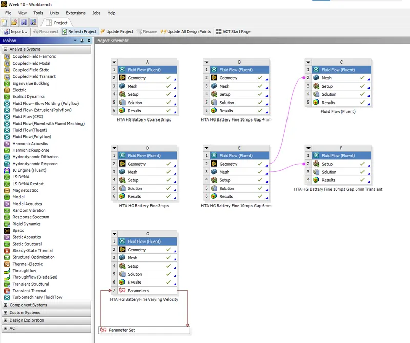
Simulation Cases Performed Using Ansys Fluent
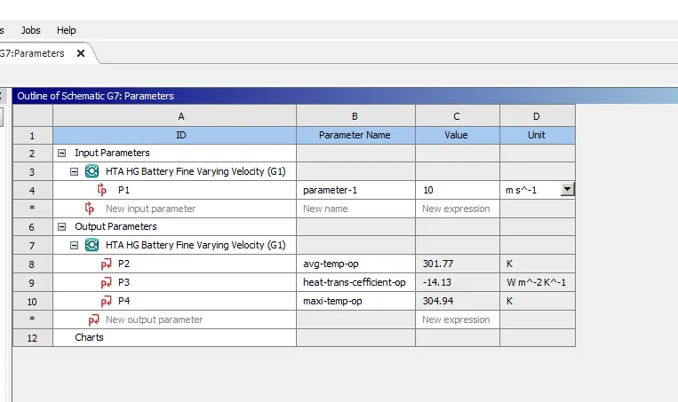
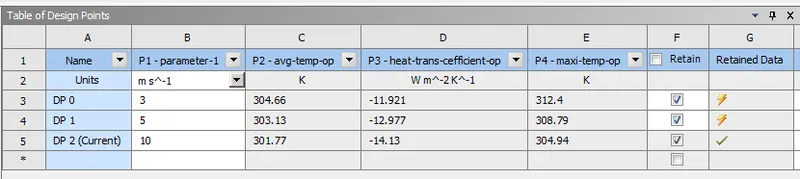
STEPS USED FOR SIMULATIONS
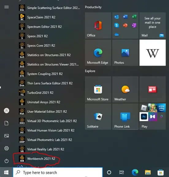
Click on red encircled "Workbench 2021 R2" as shown in the above image to start the simulation.
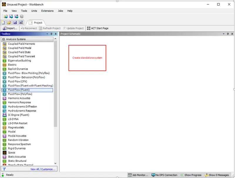
Click On Fluid Flow (Fluent) under Analysis Systems and drag it to create a standalone system. Rename the project as HTA HG Battery.
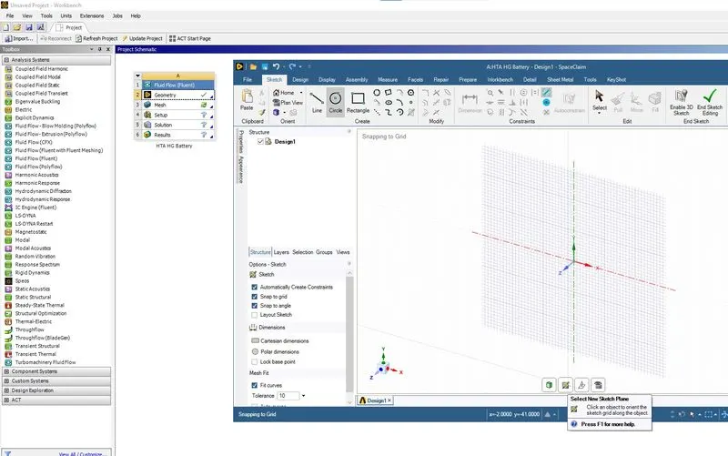
Click on the Geometry to open the space claim window. Select the new sketch plane as shown in the above image.
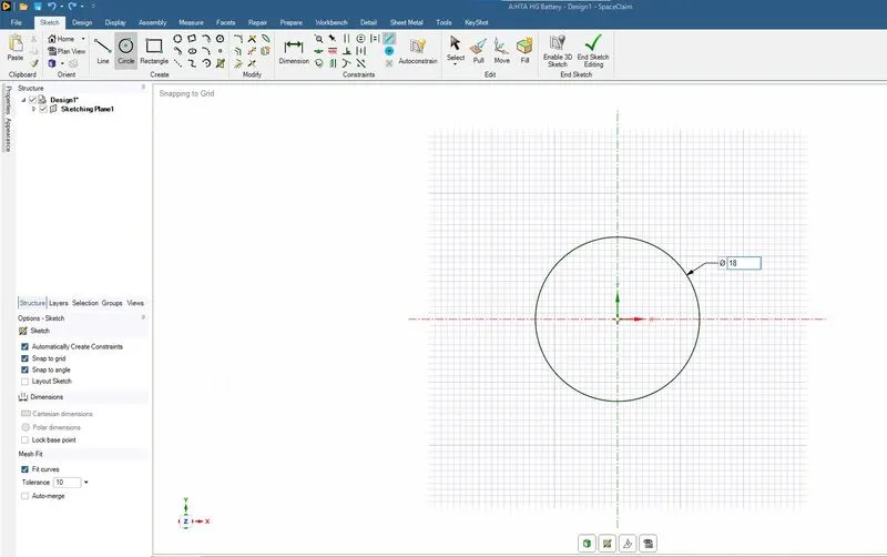
Using Circle under the sketch, a circle of diameter 18mm is drawn.
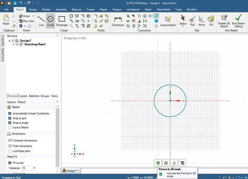
Use Return to 3D mode as shown in the above image to convert circle into cylinder.
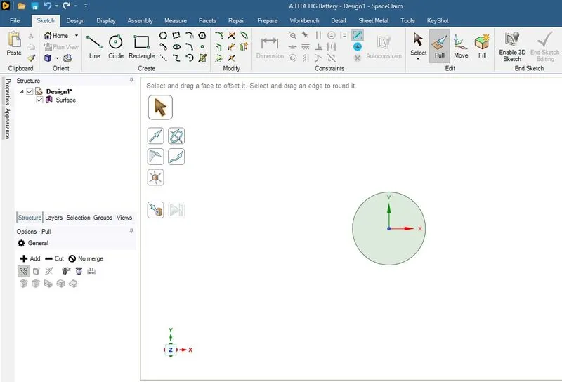
Pull command is used as shown in the above image.
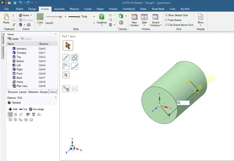
By dragging and entering the height of the cylinder, a cell of dia 18mm and height 65mmm is made.
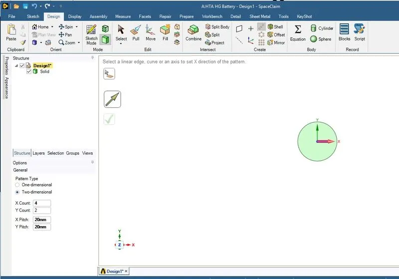
Two dimensional linear pattern is made depicting the cell arrangement with a gap of 2mm between the celllsin both direction.
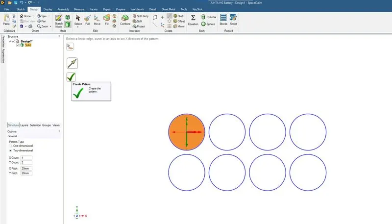
The pattern is created as shown in the above image.
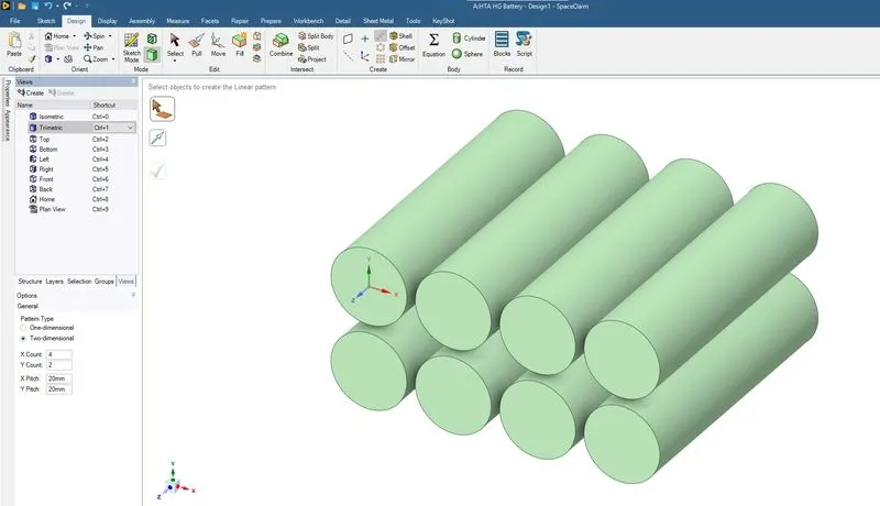
The cell arrangement in trimetric view.
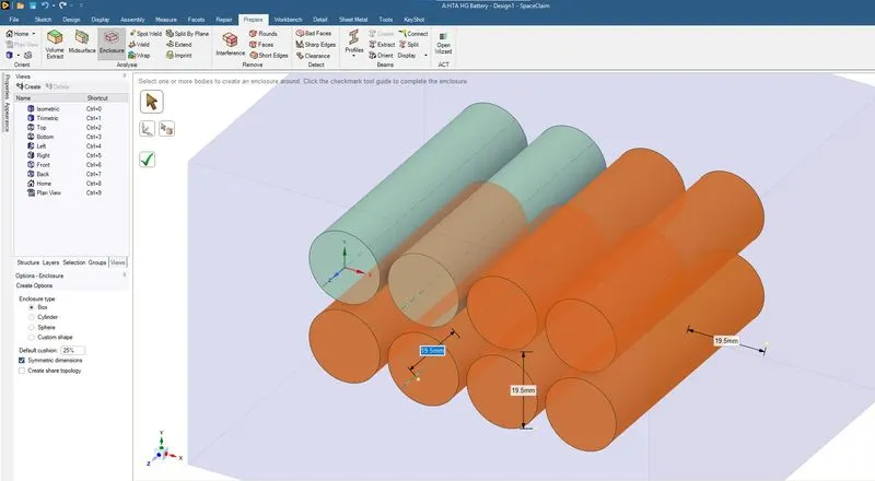
Using the enclosure under Prepare Tab an enclosure is made around the cells.
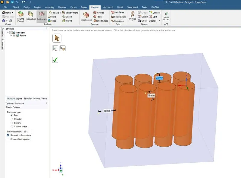
Box enclosure with symmetric dimension is selected for the enclosure and the dimension maintained are as shown in the above image.
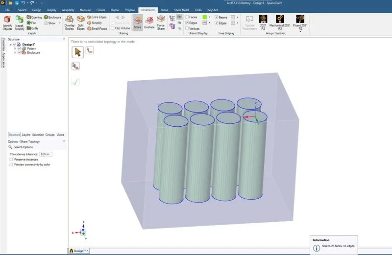
Share topology is done as shown in the above image.
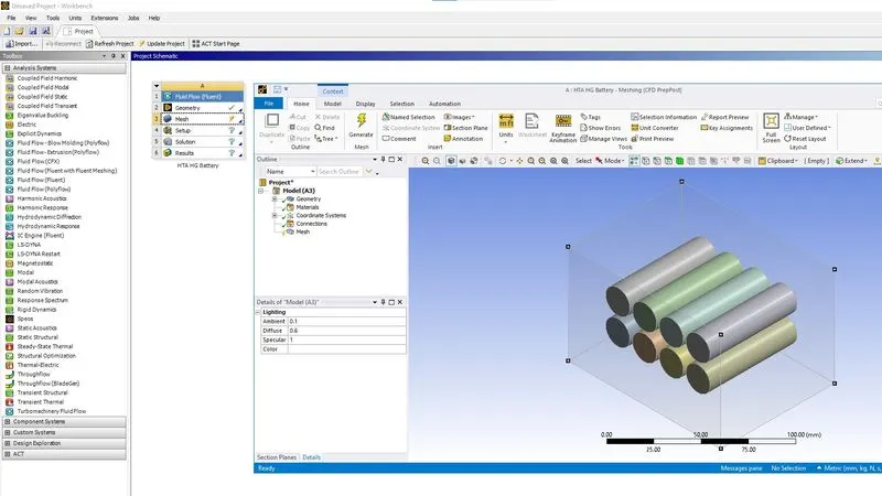
Meshing module is started as shown in the above image. The preview of the cell arrangement in the meshing module.
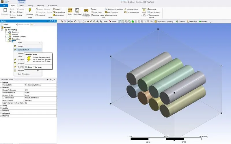
A default mesh is generated using the Generate Mesh option shown in the above image.
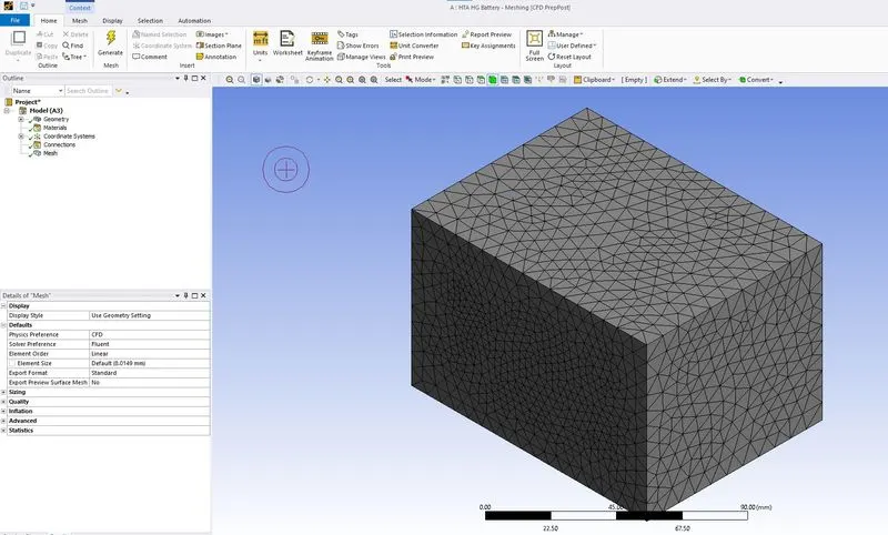
The preview of the meshing as shown in the above image.
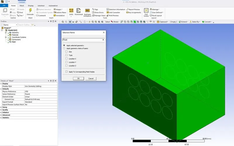
Using the Body selection & Named selection, the selected body is named as Fluid.
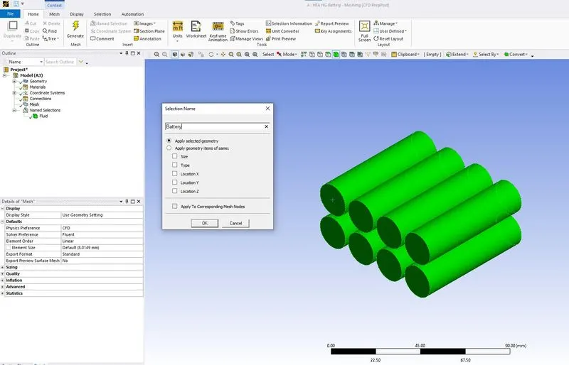
Using the Body selection & Named selection, the selected body is named as Battery.
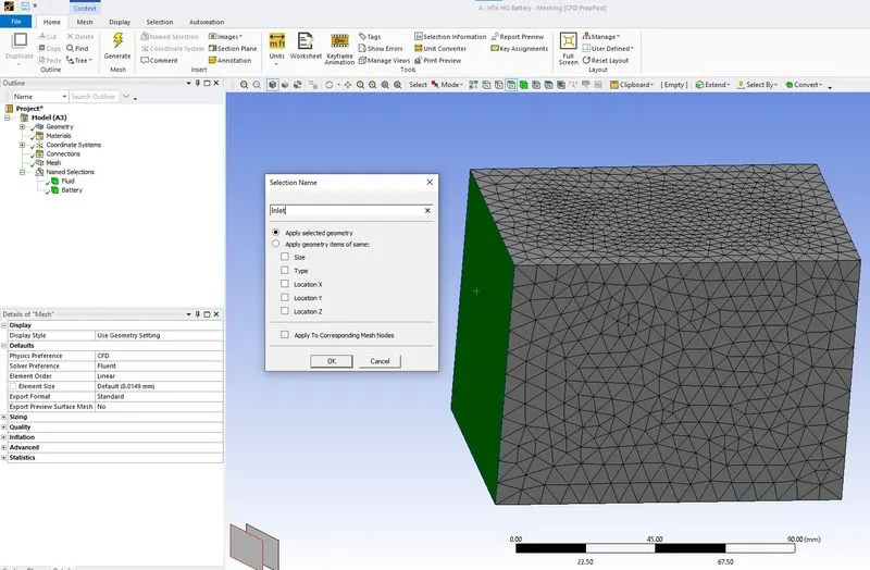
Using Named selection the selected face is named as Inlet.
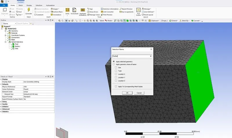
Using Named selection the selected face is named as Outlet.
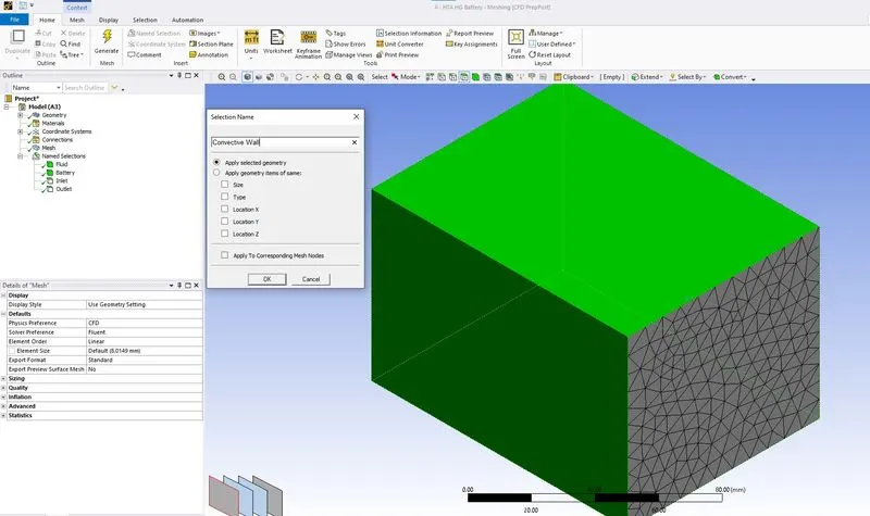
Using Named selection the selected faces are named as Convective Wall.
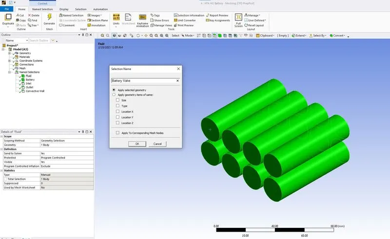
Using Named selection the selected faces are named as Battery Wall.
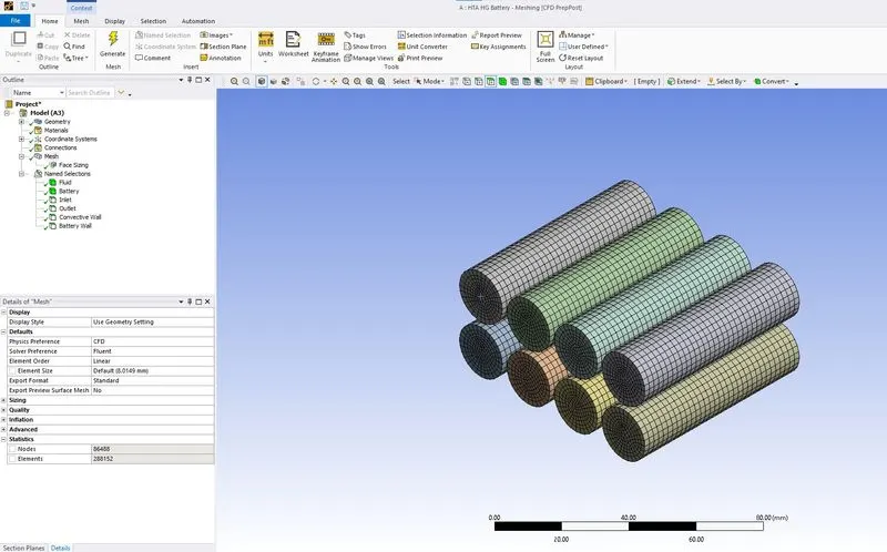
Face sizing is done as shown in the above image.
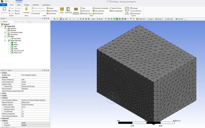
An inflation layer is defined for the battery wall as shown in the above image.
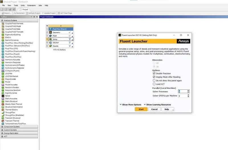
An Ansys Fluent Set Up is started as shown in the above image.
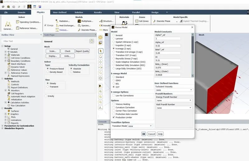
Energy is enabled and viscous model is defined as shown in the above image.
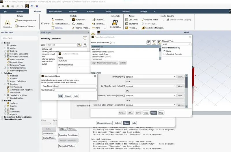
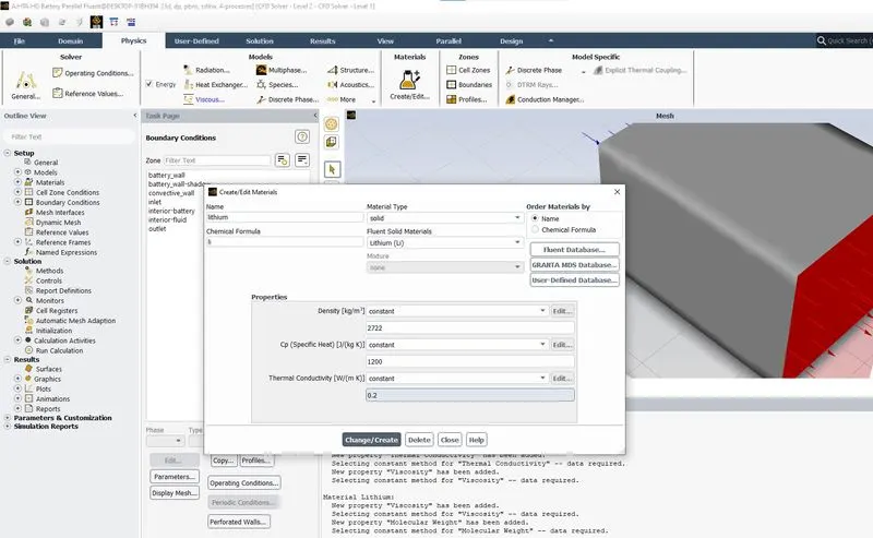
Lithium Material is define as shown in the above two image.
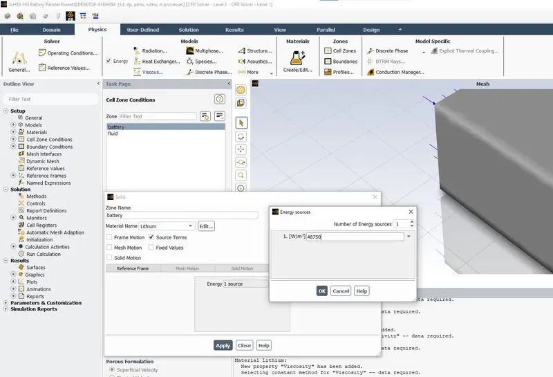
Heat source is defined as shown in the above image.
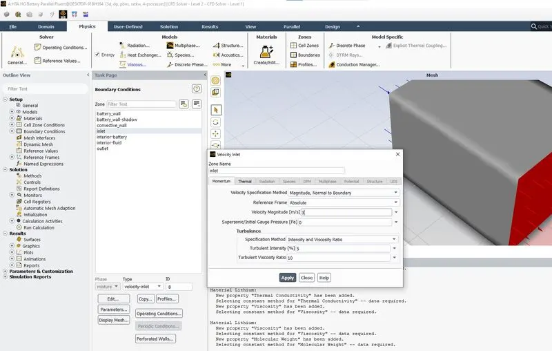
An inlet velocity is defined as shown in the above image.
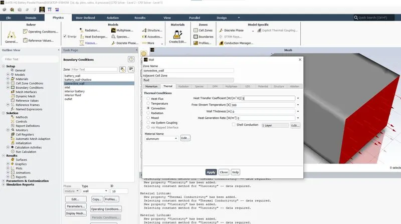
Convection on the convecting wall is defined as shown in the above image.
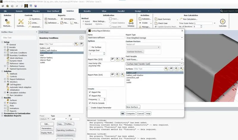
Surface report is defined as shown in the above image.
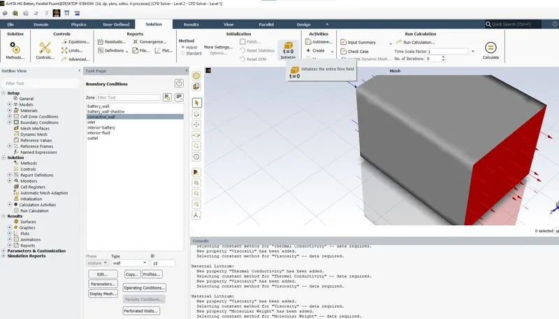
Hybrid initialization is done as shown in the above image.
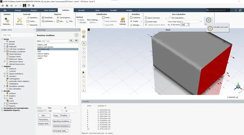
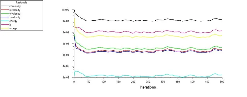
Calculation is run for 500 number of iterations.
Using the CFD post contour images are plotted.
CASE 1 : HTA HG Battery Coarse 3mps
1.1 Mesh Elements
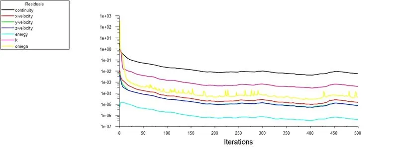
1.2 Scaled Residuals
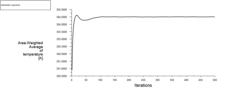
1.3 Area weighted average of temperature
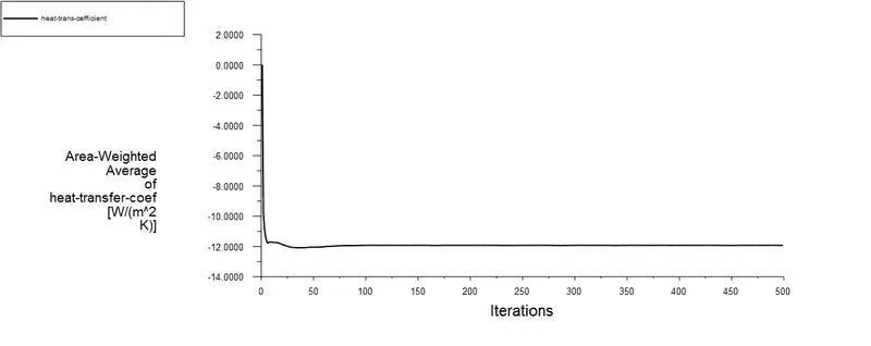
1.4 Area weighted average of heat transfer coeffiicient
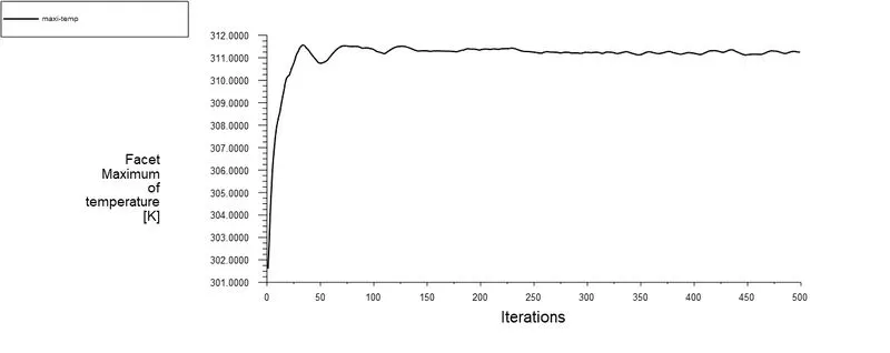
1.5 Facet Maximum of Temperature
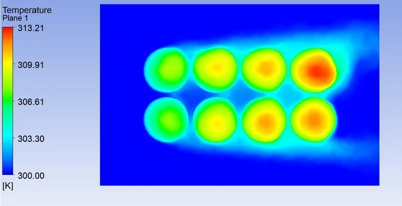
1.6 Temperature Contour (TC)
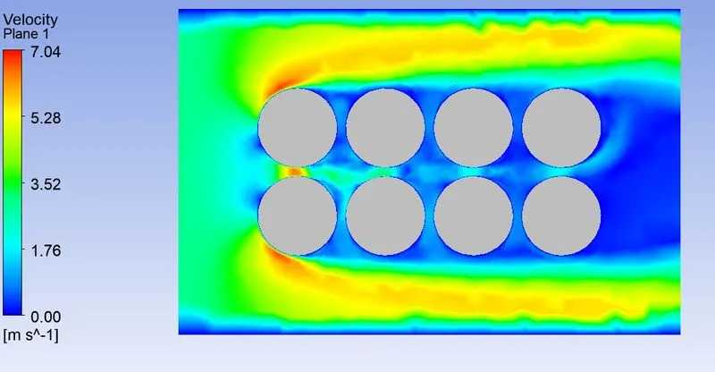
1.7 Velocity Contour
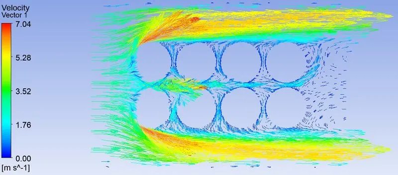
1.8 Velocity Vector (VV)
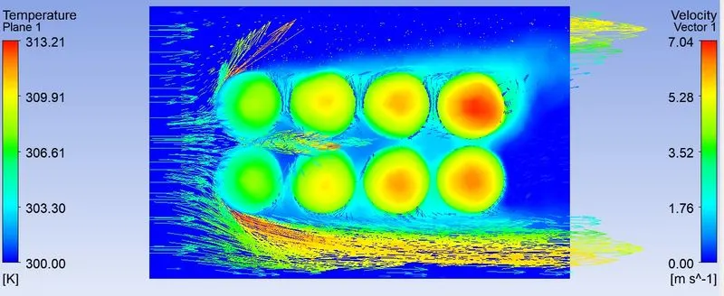
1.9 TC VV XY Plane
1.10 TC VV ZX Plane
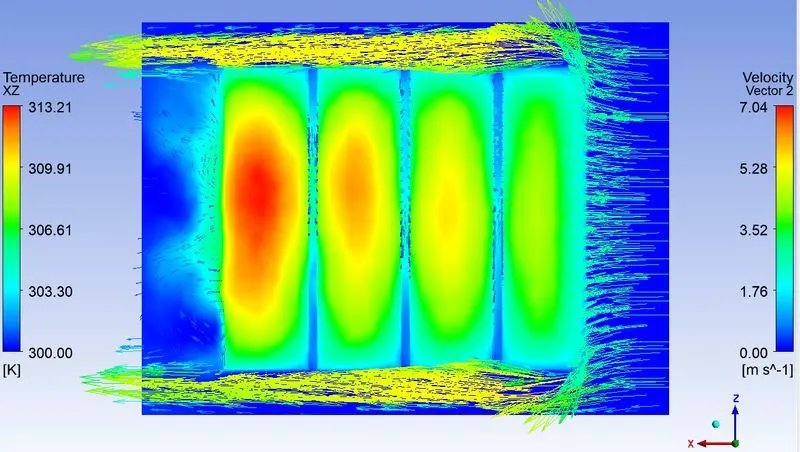
CASE 2 : HTA HG Battery Fine 3mps
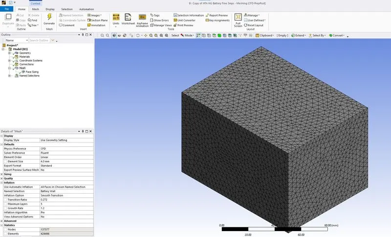
2.1 Mesh Elements
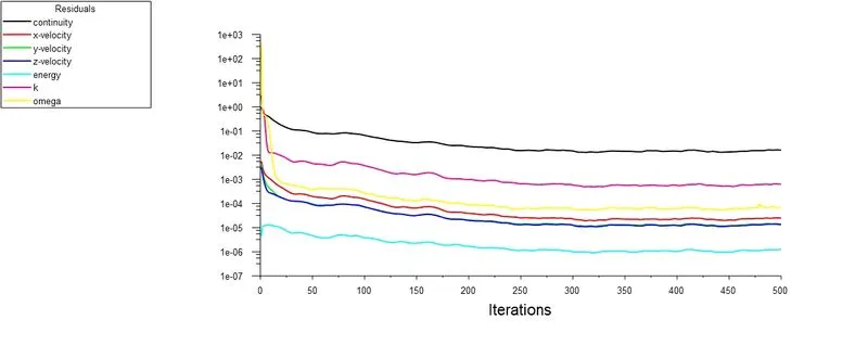
2.2 Scaled Residuals
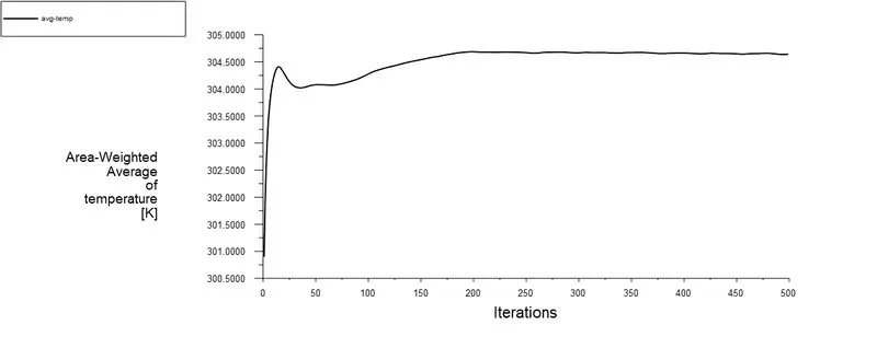
2.3 Area weighted average of temperature
2.4 Area wieghted average of heat transfer coefficient
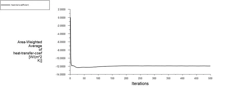
2.5 Facet Maximum of Temperature
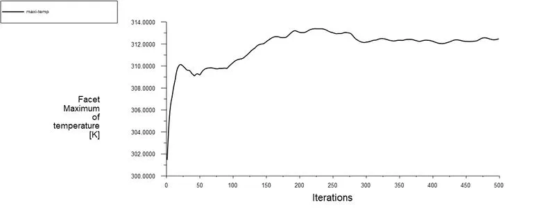
2.6 Temperature Contour (TC)
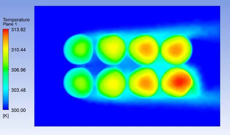
2.7 Velocity Contour
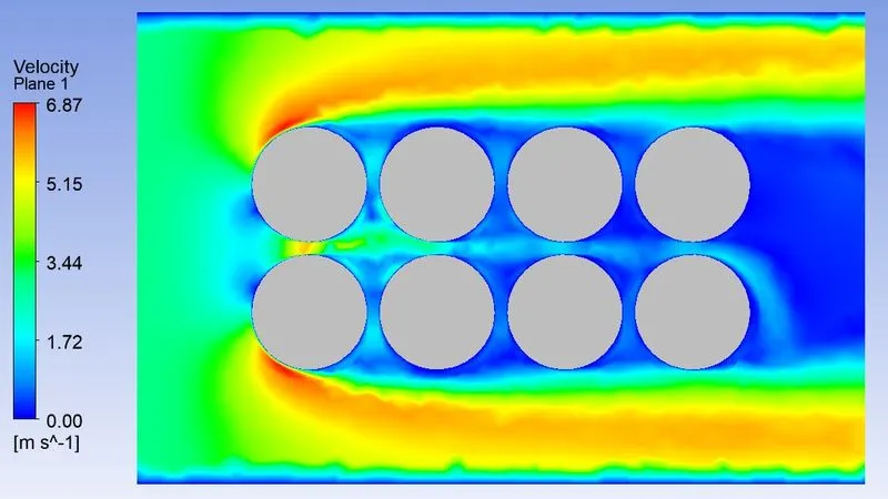
2.8 Velocity Vector (VV)
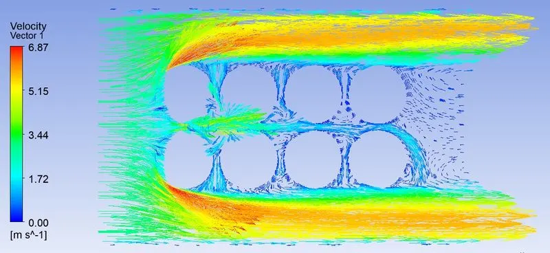
2.9 TC VV XY Plane
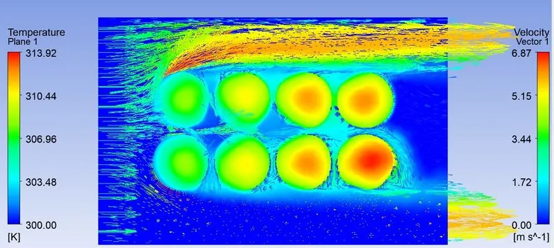
2.10 TC VV ZX Plane
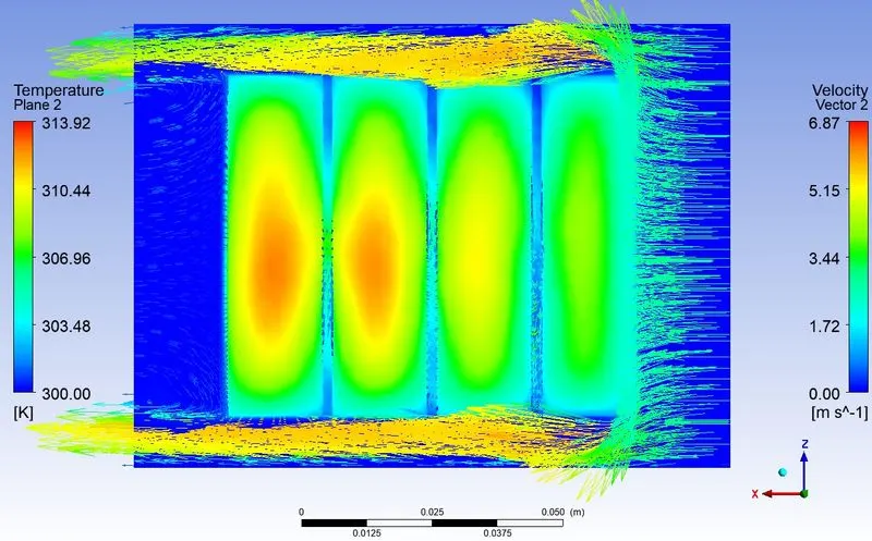
CASE 3 : HTA HG Battery Fine 5mps
3.1 Scaled Residuals
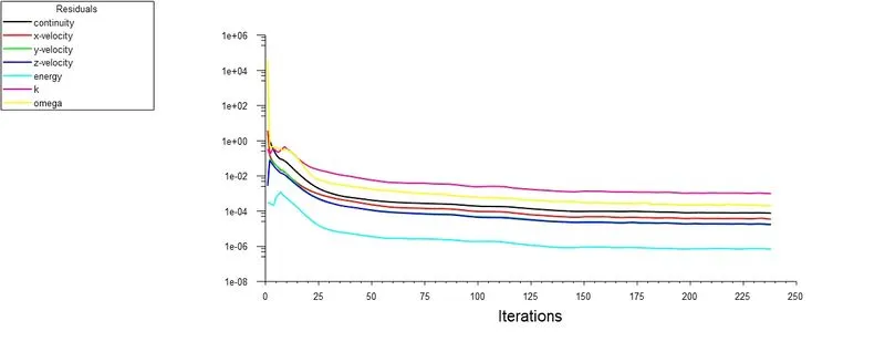
3.2 Area weighted average of temperature
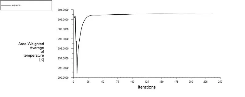
3.3 Area weighted average of heat transfer coefficient
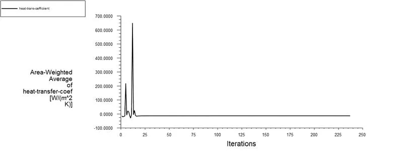
3.4 Facet Maximum of Temperature
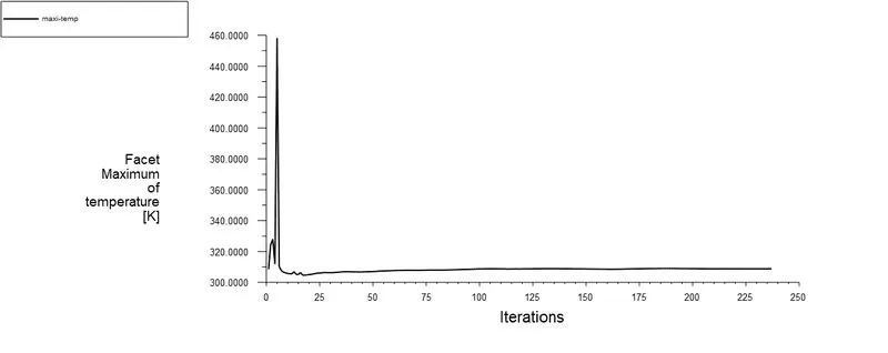
3.5 Temperature Contour (TC)
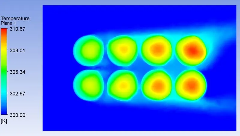
3.6 Velocity Contour
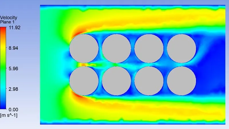
3.7 Velocity Vector (VV)
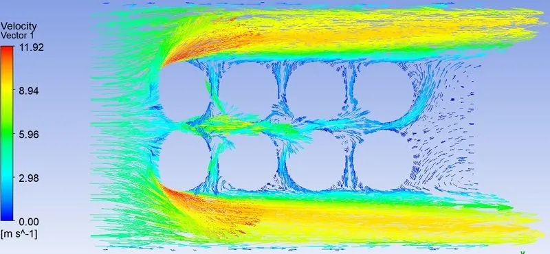
3.8 TC VV XY Plane
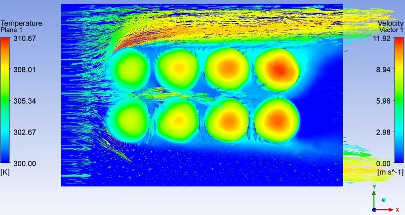
3.9 TC VV ZX Plane
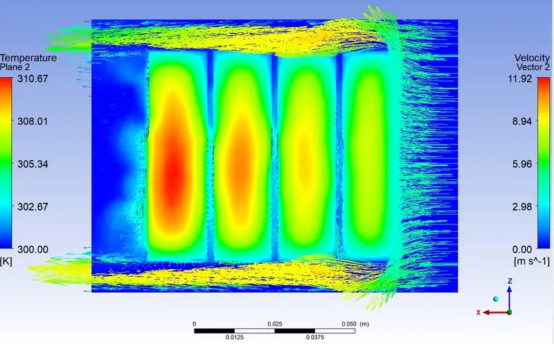
CASE 4 : HTA HG Battery Fine 10mps
4.1 Scaled Residuals
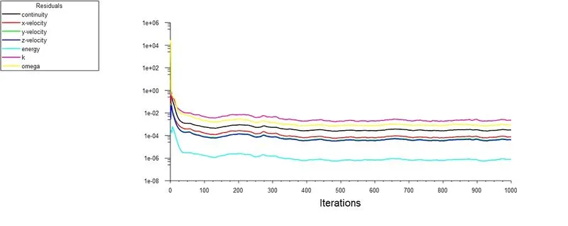
4.2 Area weighted average of temperature
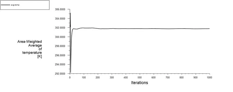
4.3 Area weighted average of heat transfer coefficient
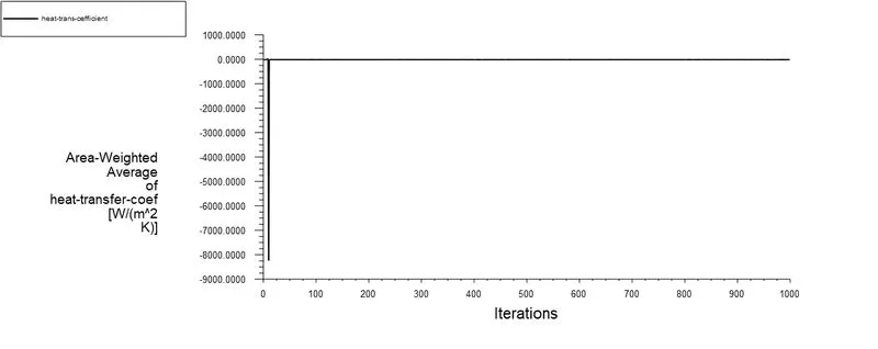
4.4 Facet Maximum of Temperature
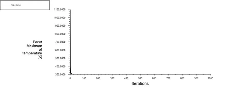
4.5 Temperature Contour (TC)
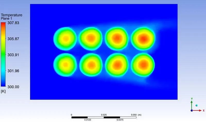
4.6 Velocity Contour
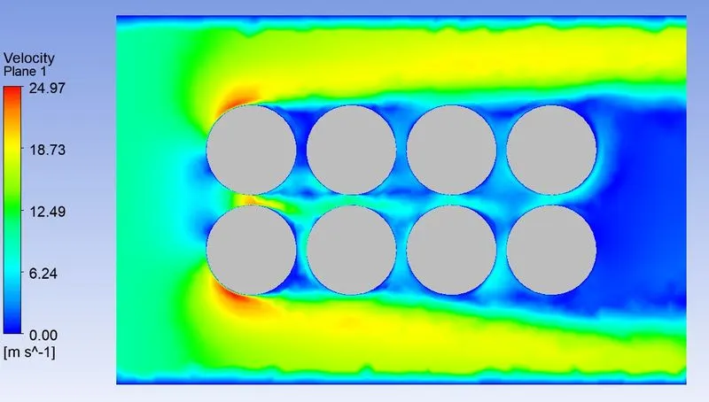
4.7 Velocity Vector (VV)
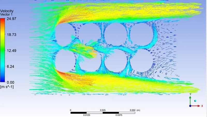
4.8 TC VV XY Plane
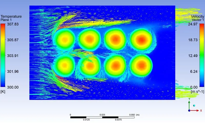
4.9 TC VV ZX Plane
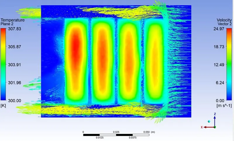
CASE 5 : HTA HG Battery Fine 10mps 4mm Gap
5.1 Scaled Residuals
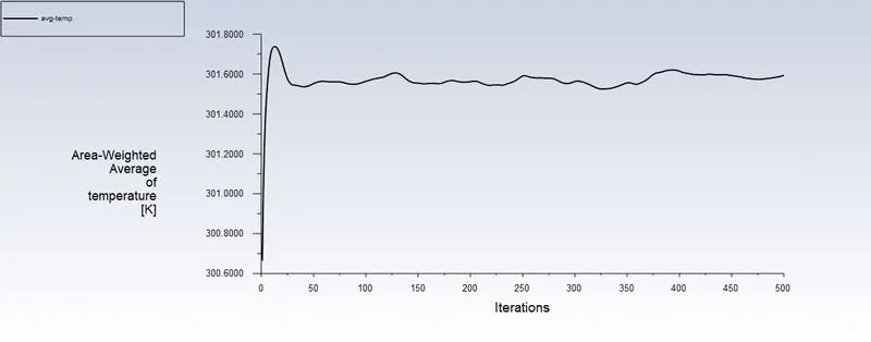
5.2 Area weighted average of temperature
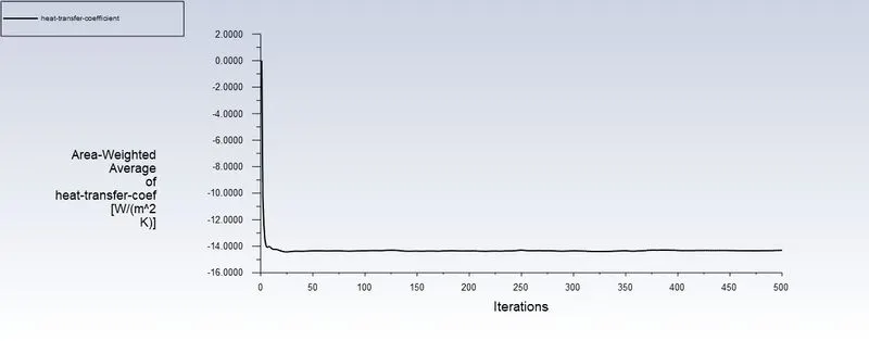
5.3 Area weighted average of heat transfer coefficient
5.4 Facet Maximum of Temperature
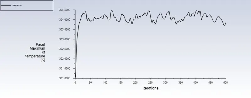
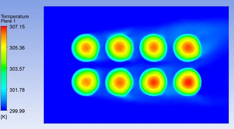
5.5 Temperature Contour (TC)
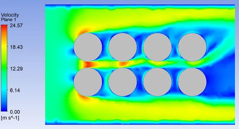
5.6 Velocity Contour
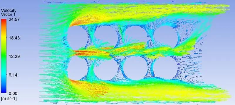
5.7 Velocity Vector (VV)
5.8 TC VV XY Plane
5.9 TC VV ZX Plane
CASE 6 : HTA HG Battery Fine 10mps 6mm Gap
6.1 Scaled Residuals
6.2 Area weighted average of temperature
6.3 Area weighted average of heat transfer coefficient
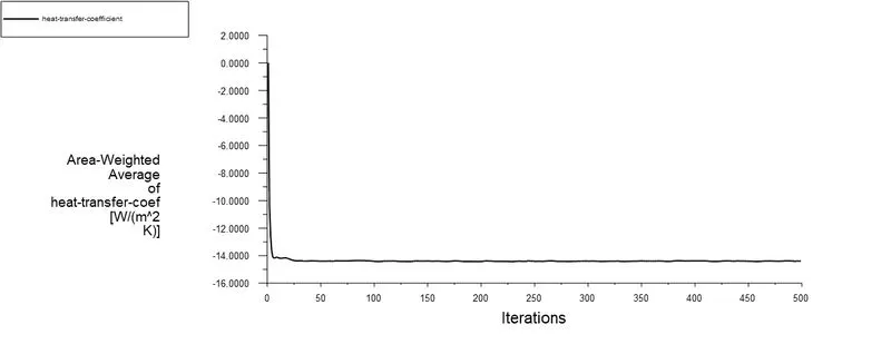
6.4 Facet Maximum of Temperature
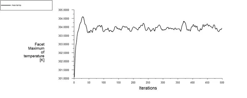
6.5 Temperature Contour (TC)
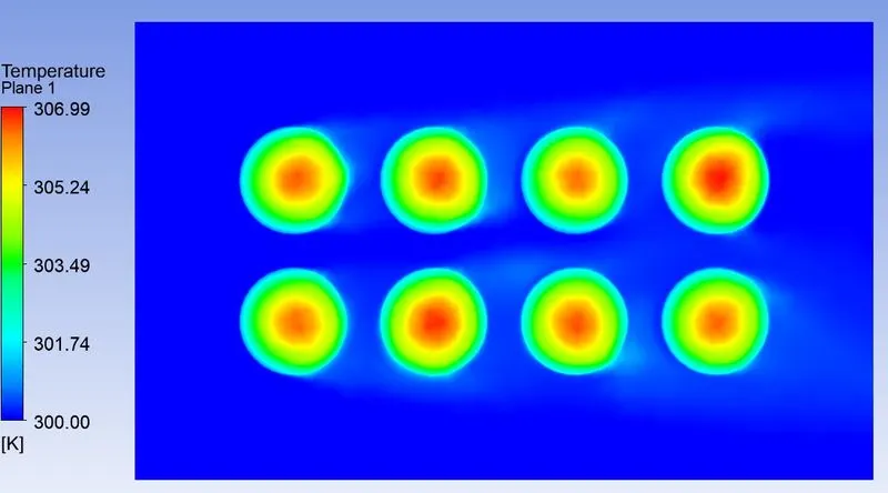
6.6 Velocity Contour
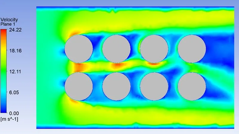
6.7 Velocity Vector (VV)
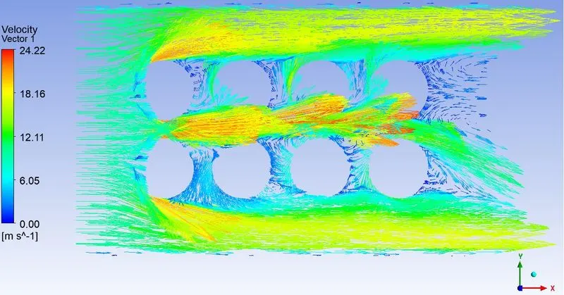
6.8 TC VV XY Plane
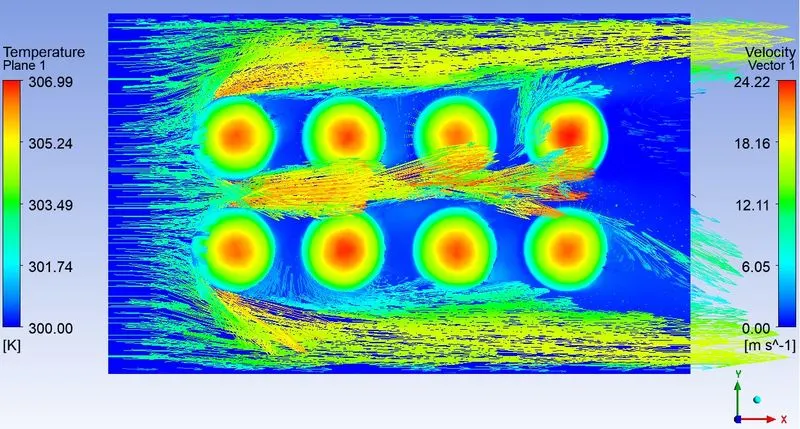
6.9 TC VV ZX Plane
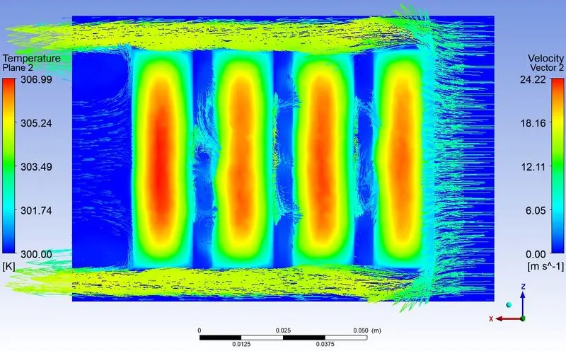
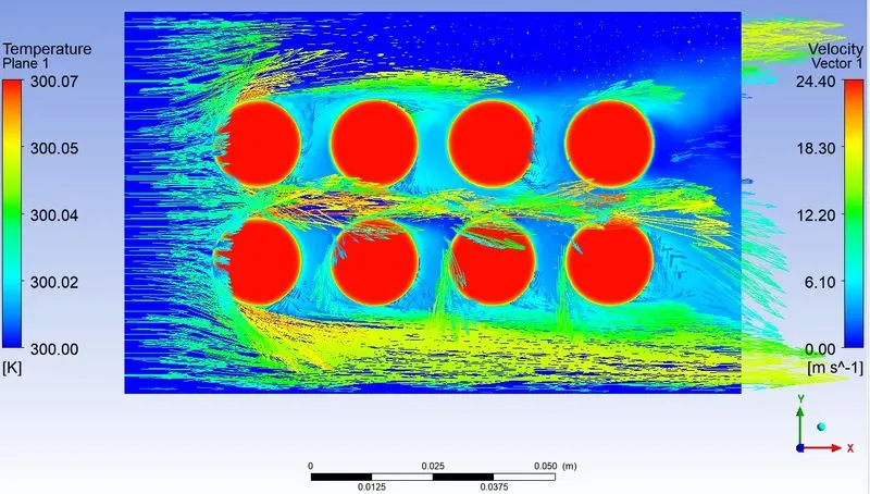
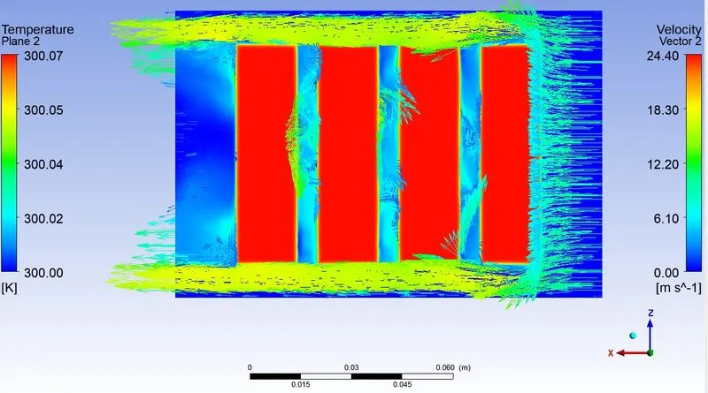
CASE 7 : HTA HG Battery Fine 10mps 6mm Gap Transient
7.1 Scaled Residuals
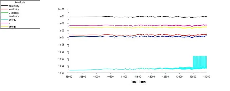
7.2 Area weighted average of temperature
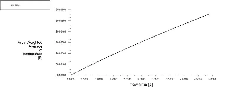
7.3 Area weighted average of heat transfer coefficient
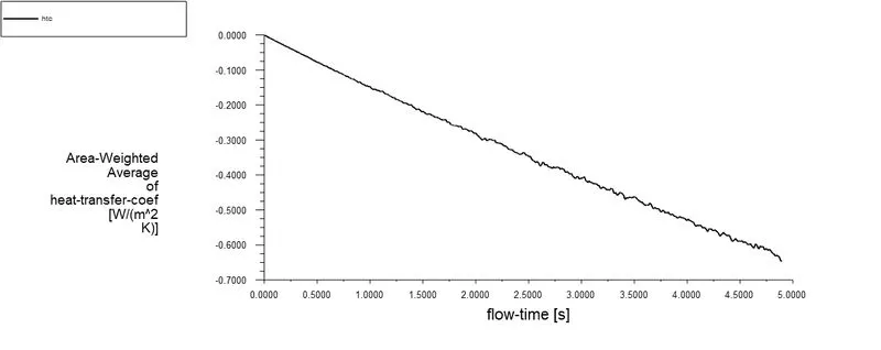
7.4 Facet Maximum of Temperature
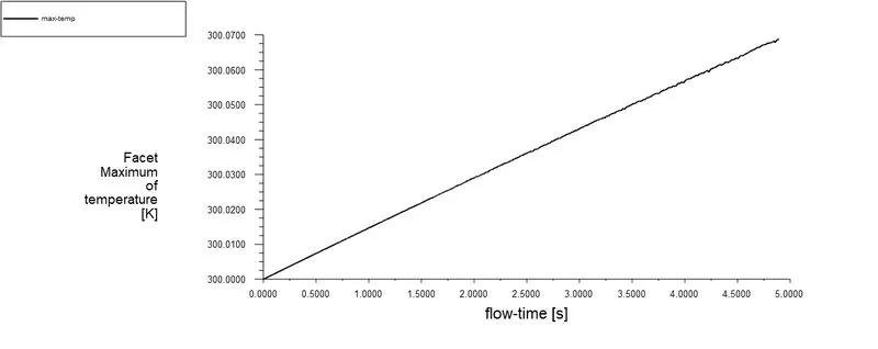
7.5 Temperature Contour (TC)
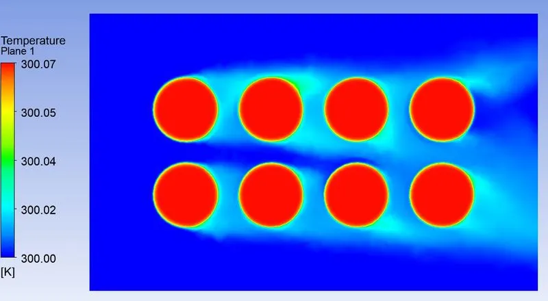
7.6 Velocity Contour
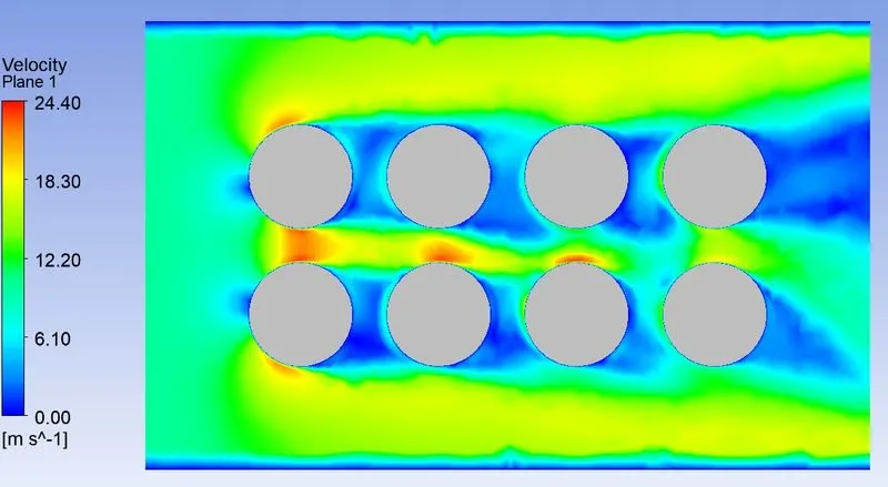
7.7 Velocity Vector (VV)
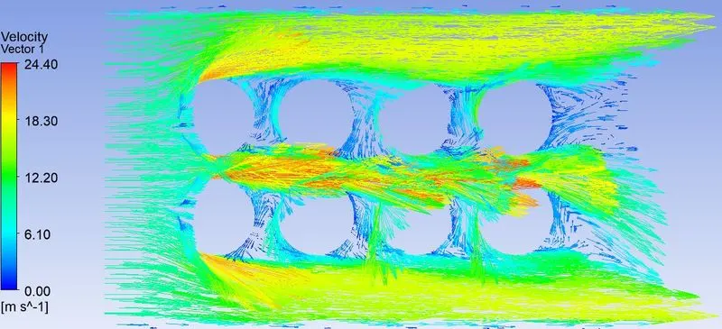
7.8 TC VV XY Plane
7.9 TC VV ZX Plane
CASE 8 : HTA HG Battery Fine 10mps 6mm Gap Different Inlet
8.1 Scaled Residuals
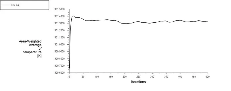
8.2 Area weighted average of temperature
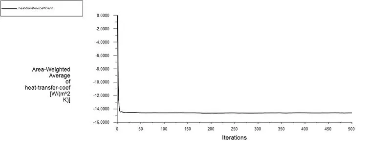
8.3 Area weighted average of heat transfer coefficient
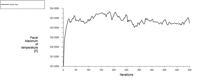
8.4 Facet Maximum of Temperature
8.5 Temperature Contour (TC)
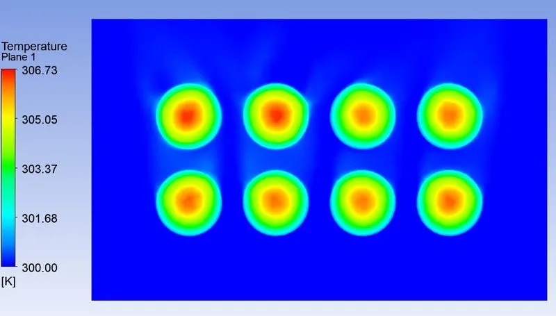
8.6 Velocity Contour
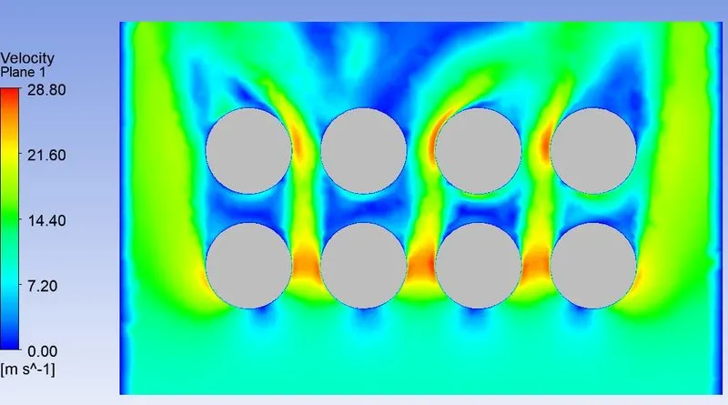
8.7 Velocity Vector (VV)
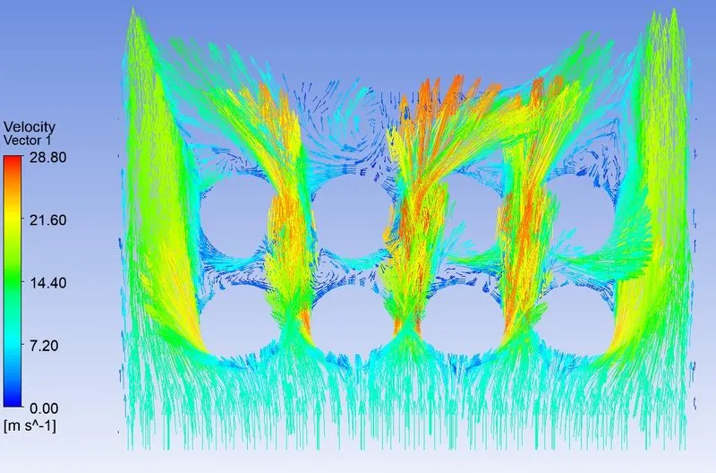
8.8 TC VV XY Plane
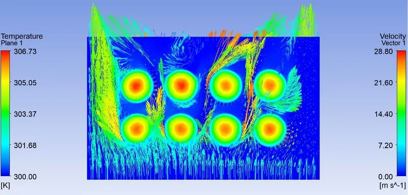
8.9 TC ZX Plane
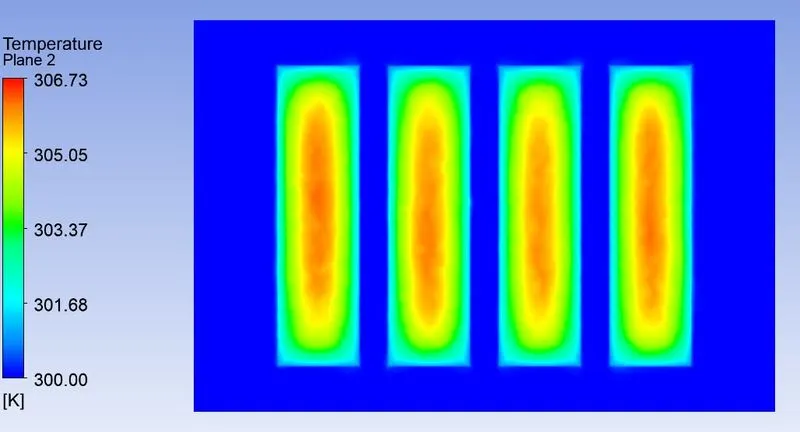
SUMMARY
Mesh Independent Study
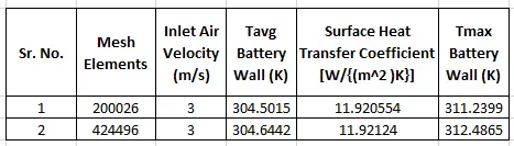
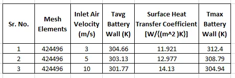
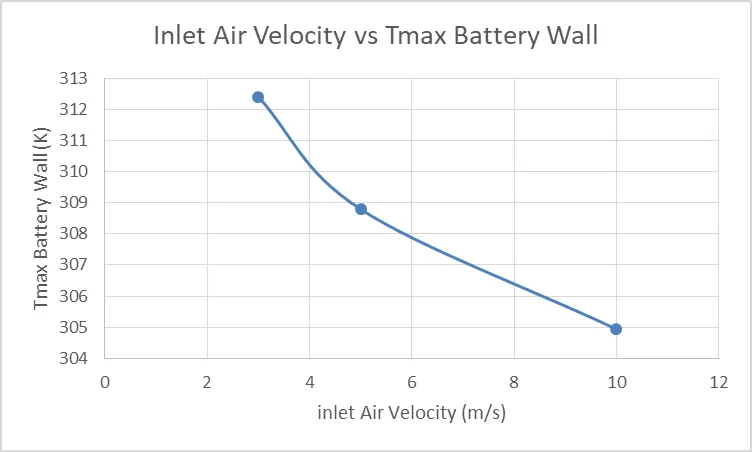
Varying Inlet Air Velocity
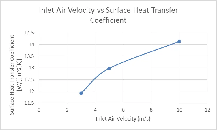
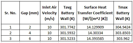
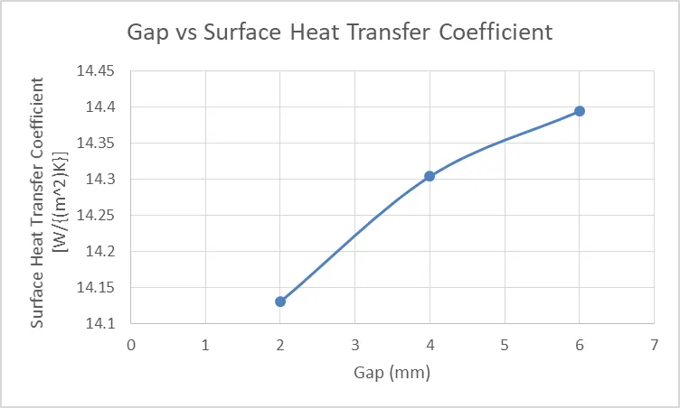
Gap Analysis
CONCLUSION
- In the mesh independent study it can be seen that there is no effective change in the parameters, the finer mesh is selected for the further study since it has inflation layer near the battery wall which will be good for capturing the near wall simulation effectively.
- With an increase in Inlet Air velocity, there is an increase in the surface heat transfer coefficient.
- The maximum temperature on the battery wall decreases with an increase in inlet air velocity.
- Ther is no noticeable change seen in the surface heat trasnfer coefficient and maximum temperature at the battery wall due to increase in the Gap between two cell.
- Ther is a change in the velocity direction of inlet air after it hits the battery wall.
- Effective way to achieve the cooling in the present scenario would be to increase the inlet air velocity.