Battery thermal management
Problem Statement:
Perform the heat transfer analysis using ANSYS-Fluent software for the cylindrical Lithium ion Battery with heat generation boundary condition. Create an enclosure and use air as the working fluid for cooling the battery back system (4 x 2). Take air inlet temperature as 300 K and gap between the batteries as 2 mm.
Property of the Lithium-ion Battery:
Density = 2700 kg/m3
Specific heat = 900 J/kg.K
Thermal Conductivity = 7.14 W/m.K
Heat Generation per battery = 10 W
Size of the Battery = 18 mm diameter and 65 mm height.
Expected results:
• Explain why battery cooling is needed. And give a brief description about various techniques for battery cooling.
• Perform Mesh independent study for any one case and based on your judgment use the more suitable model for further cases.
• Run the simulation by varying the velocity of air as 3, 5 and 10m/sec and discuss the results.
• Find out the maximum temperature and heat transfer coefficient obtained by the battery.
• Based on the results and on your judgment, select one case (3, 5 or 10 m/s) and vary the space between the batteries as 2, 4 and 6 mm, then discuss the results.
• Prove that the simulation has achieved convergence with appropriate images and plots (Velocity and temperature contour plots on the cut planes).
• Create the animation to observe the temperature distribution and velocity vector.
• Summarize the results in tabulation/ graphical form.
• Identify potential hotspots on the model.
• State the inferences based on the results.
AIM :
To perform the heat transfer analysis on the 4x2 cylindrical lithium ion battery with heat generation boundary conditions for different cases and compare the results.
OBJECTIVES :
- To create a cylindrical battery of diameter 18mm and length 65mm in spaceclaim and use pattern option to create 4x2 cylindrical batteries with different distances between the batteries for different case studies.
- To create enclosure for the 4x2 battery pack model and perform share topology in space claim.
- To generate mesh with different mesh element size for different cases and perform mesh independency study.
- To setup the simulation by giving the heat generating cell zone condition for battery and run the steady state simulation for the battery pack model of 2mm gap between batteries, and by varying the inlet velocity of air as 3m/s, 5m/s and 10m/s for different cases and compare the results.
- To select any one of the inlet velocity for performing the next simulation, by varying the gap between batteries as 3mm and 5mm for different case studies and compare the results.
- To post process the results.
Introduction to Electric vehicles:
- Conventional vehicles use fossil fuel and pollution due to combustion is a serious concern on the environment. The scope of Electric vehicles (EV) has been essential due to the adverse impact of fossil fuels on the environment.
- An electric vehicle does not use any fossil fuel for power generation and has zero emission.
- Many initiatives have been taken to reduce air pollution using non-conventional energy sources. Electric vehicles use the electric battery and help to reduce pollution. External electric supply charges the battery which supplies electric power to the motor. The electric motors transfer power to the front and back wheels.
- Many automobile industries are shifting from internal combustion engine cars to electric vehicle.
- Automotive industries have invested hugely in the research and development of electric vehicles at an affordable rate.
- Electric vehicles have several advantages like improved energy efficiency, performance, environmentally friendly and are free from combustion generated pollution.
- Technologies in electric vehicles have been developed for thermal management for battery systems, power controllers,s and electric motor.
Battery thermal management system :
Since electric vehicles have become so widely used, there is a high demand for longer battery life and higher power output. To achieve this, the battery thermal management systems will need to be able to transfer heat away from the battery pack as they are charged and discharged at higher rates. The heat generated as the battery is used can pose safety threats to the passengers. Due to the high stress and temperatures generated by the batteries, there is even higher importance on having the correct coolant and additive package. While companies such as Tesla, BMW, and LG Chem can use a traditional liquid coolant for their indirect cooling systems, continued research and development will need to be done on battery packs and coolants to advance electric vehicle safety.
- The electric vehicle has a battery management system (BMS) to provide essential information such as,
- Thermal Protection
- Over and Under voltage protection
- Over-current Protection
- Prolong battery life
- Cell Balancing
- SoC and SoH calculation
- Communication with all battery components
- Data acquisition and analysis
- The high battery temperature leads to poor performance, short lifetime, and risk of blasting. Therefore, a BTMS is essential for all battery modules.
- The main purpose of a BTMS is to maintain the battery system in the optimum temperature range and keep uniform temperature variation in the battery modules.
- Other factors for battery selection are weight, size, reliability, and the cost.
Need for Battery cooling :
- Choosing a proper cooling method for a lithium-ion (Li-ion) battery pack for electric drive vehicles (EDVs) and making an optimal cooling control strategy to keep the temperature at a optimal range of 15 °C to 35 °C is essential to increasing safety, extending the pack service life, and reducing costs.
- While advancements have been made in electric vehicle batteries that allow them to deliver more power and require less frequent charges, one of the biggest challenges that remain for battery safety is the ability to design an effective cooling system.
- In electric cars, discharging the battery generates heat; the more rapidly you discharge a battery, the more heat it generates.
- Batteries work based on the principle of a voltage differential, and at high temperatures, the electrons inside become excited which decreases the difference in voltage between the two sides of the battery. Because batteries are only manufactured to work between certain temperature extremes, they will stop working if there is no cooling system to keep it in a working range. Cooling systems need to be able to keep the battery pack in the temperature range of about 20-40 degrees Celsius, as well as keep the temperature difference within the battery pack to a minimum (no more than 5 degrees Celsius).
- If there is a large internal temperature difference, it can lead to different charge and discharge rates for each cell and deteriorate the battery pack performance.
- Potential thermal stability issues, such as capacity degradation, thermal runaway, and fire explosion, could occur if the battery overheats or if there is non-uniform temperature distribution in the battery pack. In the face of life-threatening safety issues, innovation is continually happening in the electric vehicle industry to improve the battery cooling system.
EV Batteries have specific operating ranges, which are critical for the battery life and performance. They are designed to operate at ambient temperature, which is between 68°F and 77°F (20°C and 25°C). A better control over the battery temperature improves their performance and life.
- During operation, they can withstand temperature between -22°F and 140°F (-30°C and 50°C)
- During recharges, they can withstand temperatures between 32°F and 122°F (0°C and 50°C)
Batteries generate a lot of heat during operation and their temperature must be brought down within operating ranges. At high temperatures (between 158°F and 212°F, or 70°C and 100°C), thermal runaways can occur, causing a chain reaction that destroys the battery pack.
During fast charges, batteries must be cooled down. This is because the high current going into the battery produces excess heat that must be extracted to preserve the high charging rate and not overheat the battery.
They sometimes also need to be heated up when the temperature is too low or to boost performances. For example, cells cannot be charged below 32°F (0°C). Or, companies like Tesla offer battery preheating in some models to reach high performances, going from 0 to 60 mph in less than 2 seconds.
Different types of Battery cooling methods :
- To adapt to EVs, BTMS must ensure features such as high performance, simplicity, low weight, reduced cost, low use of parasitic power and fast packaging, and easy maintenance
- Two types of battery cooling systems (BCS) are common which are external or internal. Many researchers and industries have been developing BCSs
- External Battery cooling systems (EBCS) are classified into several different ways
- Battery cooling can be categorized based on the method or technique.
- Liquid or gas cooling: plate type or use of mini-channel
- Heat pipe
- Phase Change Material (PCM)
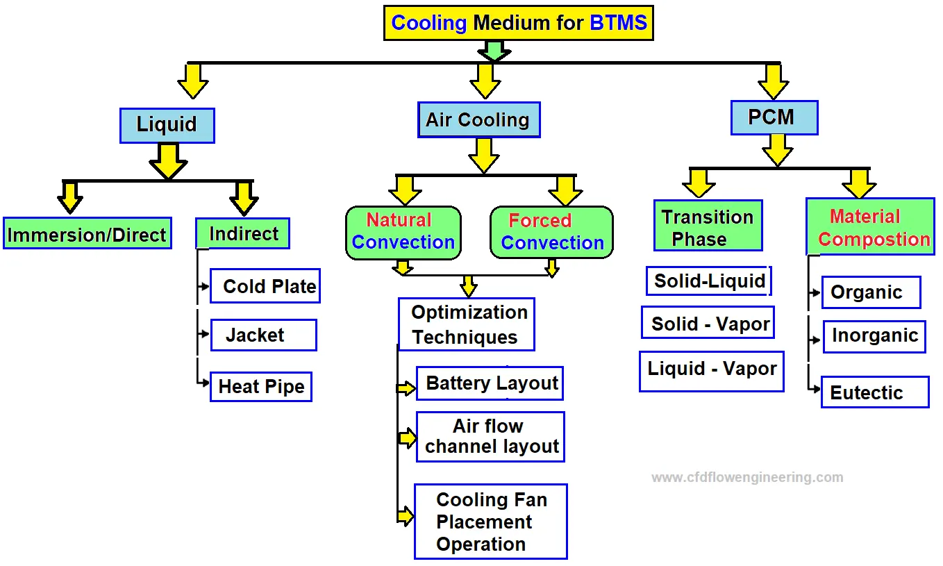
1. Air cooling :
- Air is easily available for cooling purposes and it is widely used in many industries. However, the air is not an effective coolant because of its lower heat capacity and low thermal conductivity.
- Due to low maintenance of costs, the following type of air cooling system is popular in some automobile industries like Toyota Prius and Nissan Leaf.
- The cooling is possible either by forced convection (active cooling) mode and natural convection (passive cooling) mode.
- Natural convection cooling is suitable only for low-density batteries, and typically blowers/fans can be used to enhance the convection heat transfer rate.
- When air is used for cooling of battery modules arranged in series, the middle and rear portion of batteries are at high temperature to the low heat capacity of air. The temperature of the battery pack near the outlet is very high and the temperature distribution is highly non-uniform. To cool effectively, we need to increase the flow rate and turbulence of airflow.
- CFD study of different battery modules can be carried out for different configurations of airflow rates and electric vehicles.
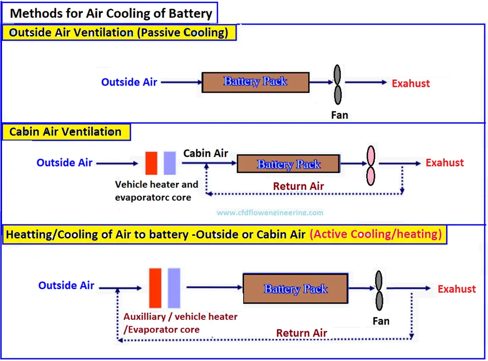
Air cooling Battery Pack in EVs :
The following are popular battery pacts with air cooling in electrical vehicles
- Honda Insight
- Honda FitEV
- Hyundai IONIQ
- Nissan e-NV 200
- Nissan Leaf
- Renault Zoe
- Toyota Prius Prime
2. Liquid cooling :
- Liquid coolants have a high convective heat removal rate due to higher density and heat capacity compared to air.
- A liquid cooling system is more compact than an air system. We can save up to 40% of separate power compared to the fans required for air cooling.
- Moreover, liquid cooling can reduce the noise level. However, the complexity of the liquid cooling system and its leakage potential can be defined into direct and indirect cooling.
Indirect liquid cooling :
- Water has been an effective coolant for several industrial applications But the main challenge is the short-circuited potential for direct cooling of batteries
- To avoid the short-circuit issue, indirect methods are effective to avoid electrical conduction with cells while maintaining high thermal diffusion
- The addition of electrical resistance may resist thermal diffusion. But its effects on cooling is not significant.
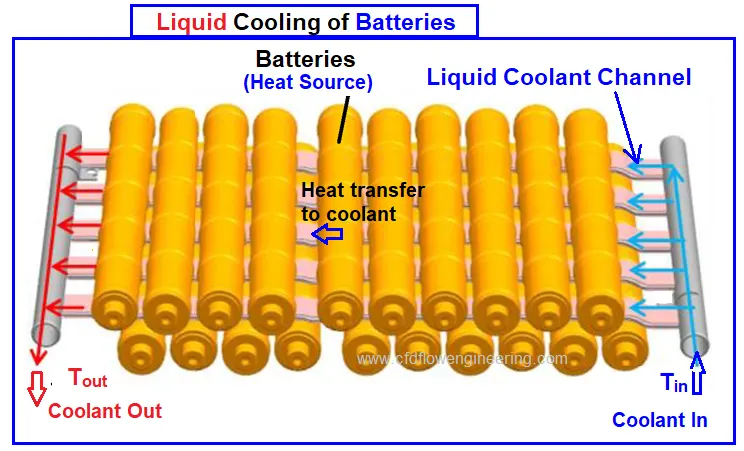
- Some EV manufacturers such as General Motors, and Tesla are using indirect cooling in their cars. General Motor used cold plates between each prismatic cell. The cold plates have several micro-channels for convective heat removal from batteries.
- Tesla has used wavy tubes placed between cylindrical cells. Thermally conductive and electrically insulated material is used to fill the gaps between the battery cells and cooling ducts.
- The wavy tubes may not be effective for cooling because of the small heat transfer contact area, it is safer from the mechanical and electrical point of view. All the connections of coolants are kept outside of the enclosure to avoid the leakage of coolant.
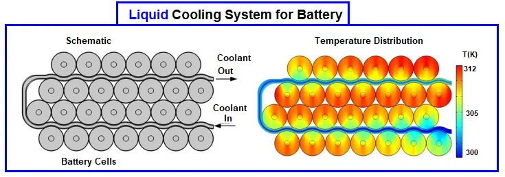
- Liquid cooling of batteries is shown below and heat transfer takes place from the cells to cooling channels
- The design strategy of thermal management system for battery modules, controller, and electric motor.
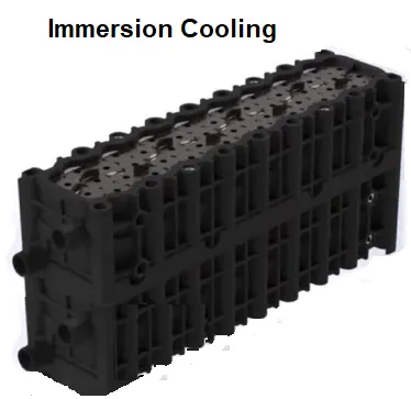
Direct liquid cooling (Immersion) :
- Direct cooling is also called immersion cooling, covers the entire surface of the cell and cools it uniformly
- Immersion cooling removes hot or cold spots in the cell and significantly improves the performance of the cell.
- Ideal coolant mush be dielectric with minimum viscosity and high thermal conductivity and thermal capacity
- Immersion cooling is widely used for data center servers and high-power electronics devices
- BTMS for this method is not suitable for most mass-produced EV due to high cost and safety concerns
- Immersion cooling is useful for batteries of high-performing EVs and EV racing. The fluid has a boiling point between 60 – 80 °C to prevent overheating of the cells and avoid thermal runaway. Modular type containers are used for the cells where they can be submerged in the liquid
Liquid cooling Battery pack in EVs :
The following are popular battery pacts with liquid cooling in electrical vehicles
- Audi R8 e-Tron
- Ford Focus
- GM Chevrolet Bolt and Chevrolet Volt
- Tesla Model X, Model S, Model 3
- Toyota –iQ
- Volvo XC90 T8
3. Phase change material (PCM) Cooling :
- The phase change material absorbs heat significantly due to high latent heat during battery discharge
- The PCMs have been used for thermal management have a melting point in the optimum performing range of lithium cells. The cell temperature needs to remain for a long time.
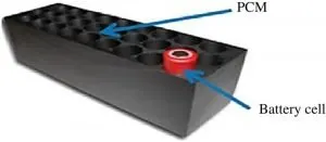
- PCM as paraffin has a melting point in the range of 32-38°C which is mixed with graphite flakes to improve thermal conductivity
- The graphite flakes will also create a semi-matrix block which will contain the paraffin particles. When the paraffin melts, it stays within this matrix and the whole composition remains as the solid form
- The basic equation for phase change material (PCM): V*ρ*L = P*t, where
V = Volume of PCM in cell (m3)
ρ = Density of PCM in cell (kg/m3)
L = Latent heat of fusion of PCM (per kg)
P = Power absorbed (Watt)
t = Time of power absorption (seconds)
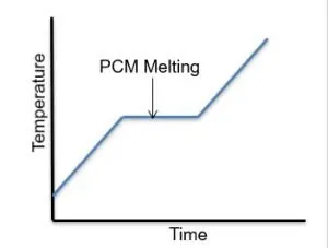
- The advantage of solid PCM is that they also act as shields, in case one cell enters a thermal runaway
- Classification of PCM materials for battery cooling is given below
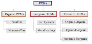
- Multiphase modeling needs to be considered for phase change materials during the cooling of batteries
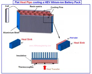
4. Heat pipe :
- Heat pipes have been considered versatile in many industrial applications for their efficient cooling and
thermal management - Similar to the passive cooling method of PCM, applying the heat pipes to cool or remove heat energy from the battery provides efficient
heat transfer t low power consumption - In this mechanism, heat is transferred through latent heat of vaporization (phase change) from the evaporator to the condense
- The working fluid can be passively transported back to the evaporator by capillary pressures it is developed
within a porous wick lining. Operating in this situation the heat is continuously absorbed and released.
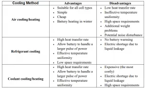
Comparison of cooling methods :
- Commonly used cooling methods are compared in the following table
CASE SETUP :
- In this simulation, we are going to find out the maximum temperature of the battery for different inlet velocities of air (3m/s, 5m/s, and 10m/s), and by changing the space between the batteries (2mm, 4mm and 6mm). Then, find out the optimum cooling method by comparing the results of different cases.
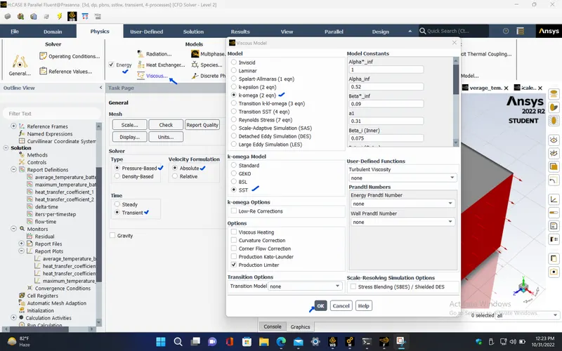
- For this simulation, we choose the k-omega SST model turbulence model which gives more accurate results compared to other turbulence models. This is because the use of k-omega formulation in the inner parts of the boundary layer makes the model directly usable all the way down to the wall through the viscous sub-layer and also the SST formulation also switches to a k-epsilon behaviour in the free-stream and thereby avoids the common k-omega problem that the model is too sensitive to the inlet free-stream turbulence properties. The k-omega SST(Shear Stress Transport) is a two equation eddy-viscosity model which has good behaviour in adverse pressure gradients and flow separation.
- We take the battery as the heat source. The heat generation rate by the battery is given as 10 Watts, and the volume of the cylindrical battery can be calculated.
We know that,
Power density of the battery = Heat generation rate by the battery / Volume of the battery
Hence the power density of the battery can be written as,
`q^. = 10 / ((pi/4) * 0.018^2 * 0.065)`
`q^. = 604577 " W/m^3"`
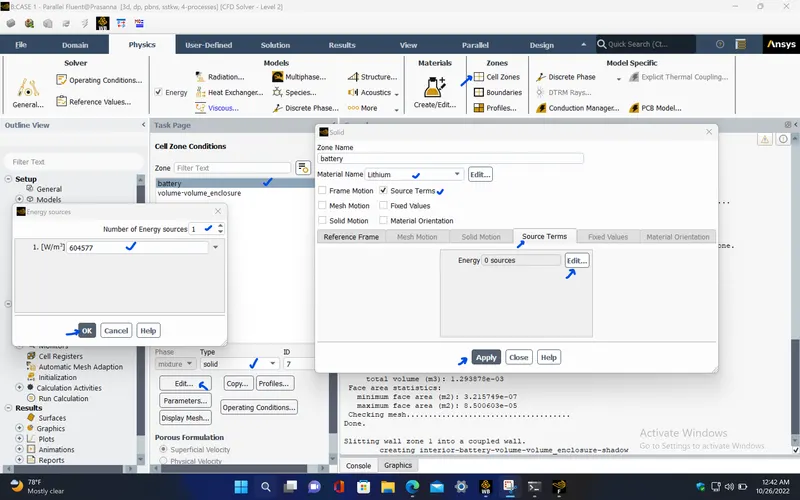
This value should be given under cell zone conditions of the battery which is taken as the heat source for this simulation.
The following table shows the different case study approaches which are considered for the heat transfer analysis,
|
|
SOLVER TIME |
MESH ELEMENT SIZE |
INLET VELOCITY OF AIR ('m/s') |
GAP BETWEEN THE BATTERIES ('mm') |
|
CASE 1 |
Steady state |
Baseline mesh |
3 |
2 |
|
CASE 2 |
Steady state |
Fine mesh (2.5mm, without boundary layers) |
3 |
2 |
|
CASE 3 |
Steady state |
Refined mesh (3mm, with boundary layers) |
3 |
2 |
|
CASE 4 |
Steady state |
5 |
2 |
|
|
CASE 5 |
Steady state |
10 |
2 |
|
|
CASE 6 |
Steady state |
10 |
4 |
|
|
CASE 7 |
Steady state |
10 |
6 |
|
|
CASE 8 |
Transient state |
10 |
4 |
PROCEDURE :
CASE 1 (For 2mm gap and 3m/s - Baseline mesh) :
PRE-PROCESSING :
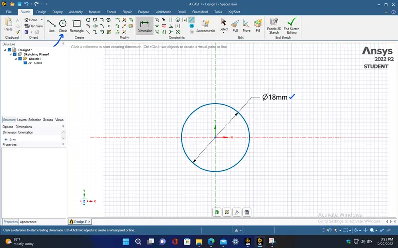
- Create the circle of diameter 18mm diameter in spaceclaim.
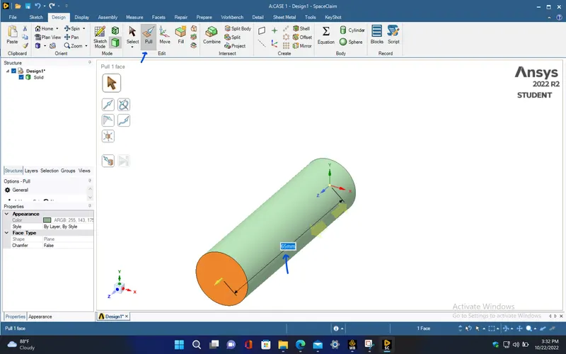
- Extrude the circle to create a cylinder with length of 65mm using pull tool.
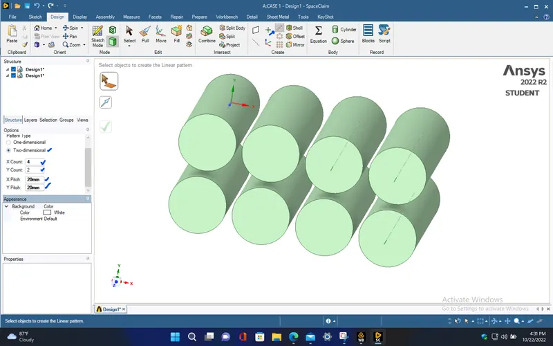
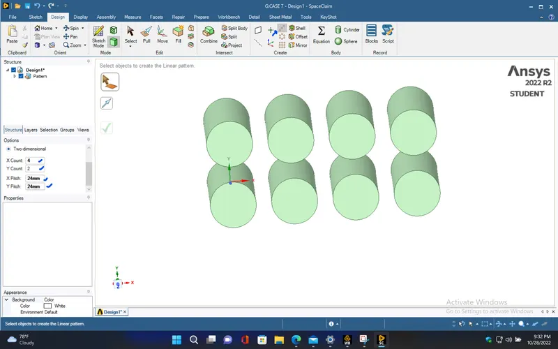
- Now, to create multiple number of cylinders in order of 4x2 which is to be the Lithium-ion batteries, use pattern option under design menu tab. Give the X count and Y count as 4 and 2 respectively, also specify the X pitch and Y pitch length as 20mm which creates a 2mm gap between the cylinders.
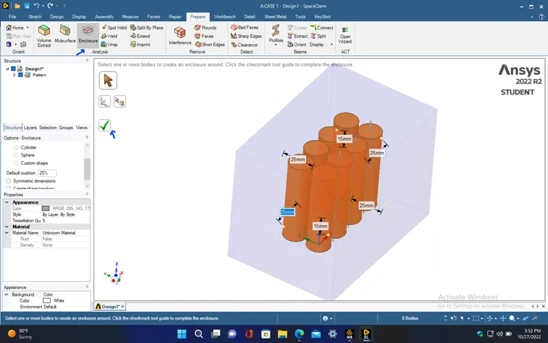
- Now, create an enclosure for the 4x2 cylinrical batteries with required dimensions.
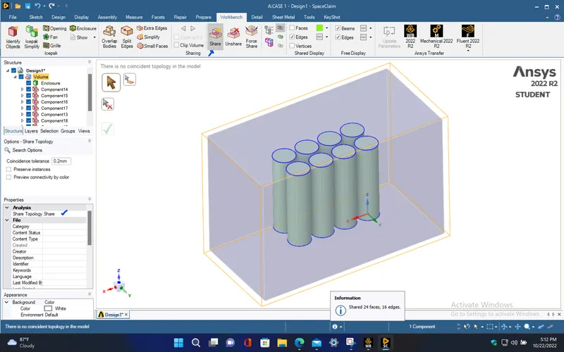
- Now, to share the information between the enclosure and the cylinders, perform share topology. This is used to create the conformal mesh on the domain.
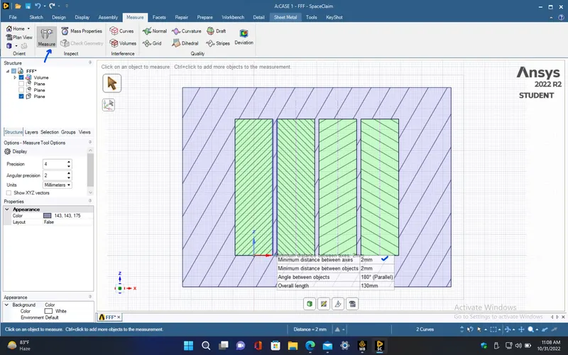
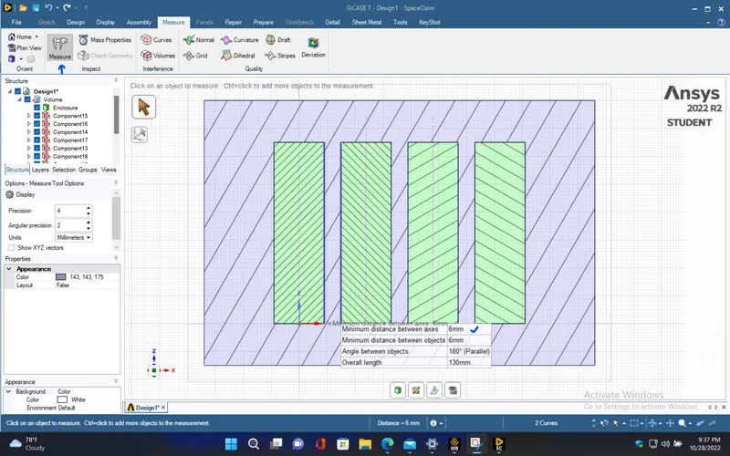
- Use measure tool to check if the gap between any two consecutive cylinders are 2mm. Then, save the model and close the spaceclaim.
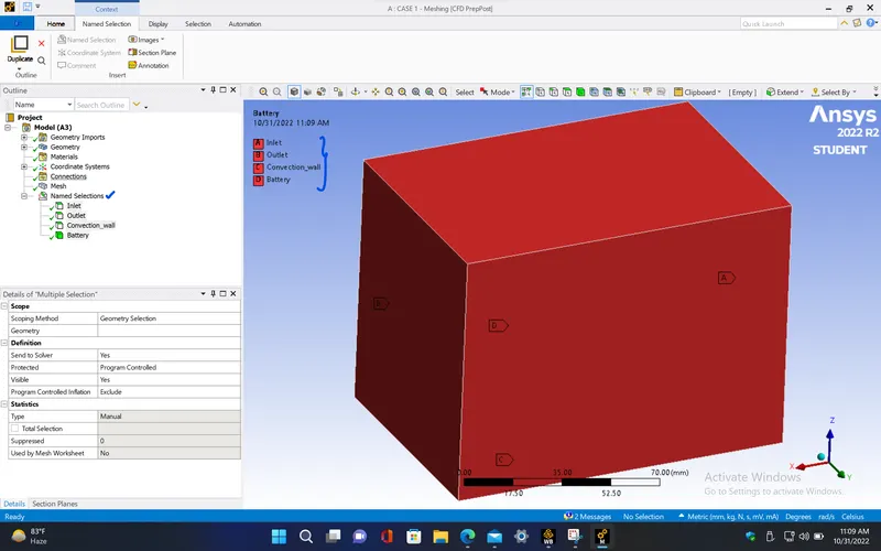
- Open the mesh window and give name selections to every regions of the Battery pack model.
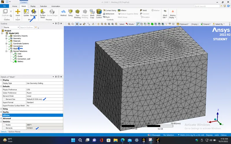
- Now, generate mesh by keeping the default mesh element size for the moel.
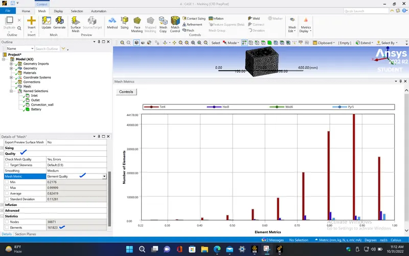
- Here, since most number of mesh elements have about 90% element quality, this can be proceeded for the simulation.
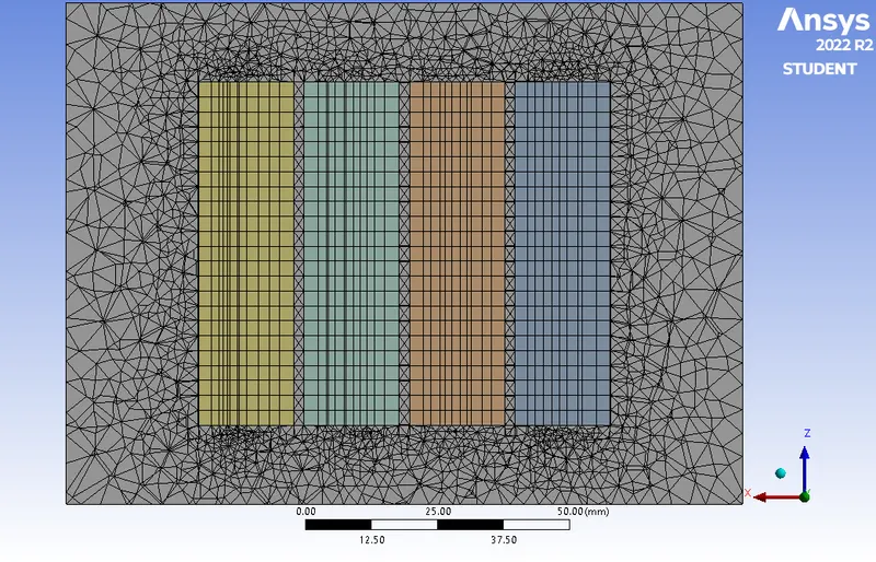
- Cross sectional view
|
Cells |
Faces |
Nodes |
|
161823 |
344621 |
43641 |
SETUP AND SOLVING :
- The following parameters has been set for this simulation.
|
Model |
Settings |
|
Space |
3D |
|
Time |
Steady |
|
Viscous |
SST k-omega turbulence model |
|
Heat Transfer |
Enabled |
Material properties :
|
Fluid |
air |
|
Density |
1.225 kg/m^3 |
|
Cp (Specific Heat) |
1006.43 J/(kg K) |
|
Thermal Conductivity |
0.0242 W/(m K) |
|
Viscosity |
1.7894e-05 kg/(m s) |
|
Molecular Weight |
28.966 kg/kmol |
|
Solid |
lithium |
|
Density |
2700 kg/m^3 |
|
Cp (Specific Heat) |
900 J/(kg K) |
|
Thermal Conductivity |
7.14 W/(m K) |
|
Solid |
aluminum |
|
Density |
2719 kg/m^3 |
|
Cp (Specific Heat) |
871 J/(kg K) |
|
Thermal Conductivity |
202.4 W/(m K) |
Cell zone conditions :
|
Fluid |
volume-volume_enclosure |
|
Material Name |
air |
|
Solid |
battery |
|
Material Name |
lithium |
|
Specify source terms? |
yes |
|
energy |
604577 |
Boundary conditions :
|
inlet |
|
|
Velocity Specification Method |
Magnitude, Normal to Boundary |
|
Reference Frame |
Absolute |
|
Velocity Magnitude [m/s] |
3 |
|
Supersonic/Initial Gauge Pressure [Pa] |
0 |
|
Temperature [K] |
300 |
|
outlet |
|
|
Backflow Reference Frame |
Absolute |
|
Gauge Pressure [Pa] |
0 |
|
Backflow Total Temperature [K] |
300 |
|
Backflow Direction Specification Method |
Normal to Boundary |
|
Wall |
|
|
interior-battery-volume-volume_enclosure-shadow |
|
|
Material Name |
lithium |
|
Thermal BC Type |
Coupled |
|
Wall Motion |
Stationary Wall |
|
Shear Boundary Condition |
No Slip |
|
interior-battery-volume-volume_enclosure |
|
|
Material Name |
lithium |
|
Thermal BC Type |
Coupled |
|
convection_wall |
|
|
Material Name |
aluminum |
|
Thermal BC Type |
Convection |
|
Convective Heat Transfer Coefficient [W/(m^2 K)] |
5 |
|
Free Stream Temperature [K] |
300 |
|
Wall Motion |
Stationary Wall |
|
Shear Boundary Condition |
No Slip |
Solution method :
|
Pressure-Velocity Coupling |
Coupled |
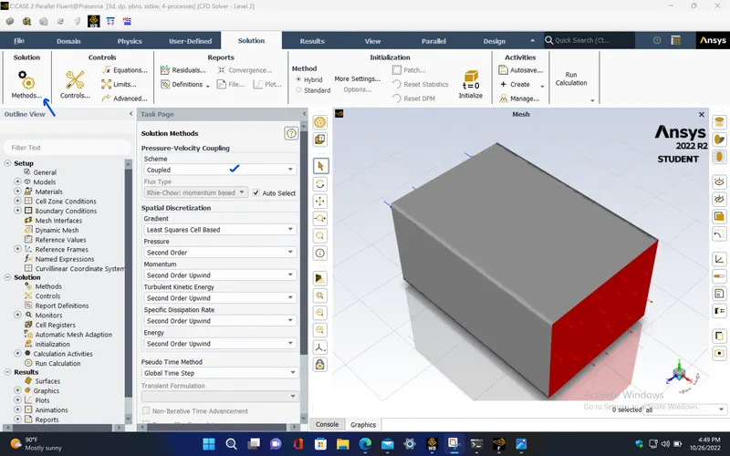
- Here, we use k-omega SST turbulence model which is more effective turbulence model for this simulation since it gives more accurate results compared to other models because of the use of k-ω formulation in the inner parts of the boundary layer makes the model directly usable all the way down to the wall through the viscous sub-layer, and the SST formulation also switches to a k-ε behaviour in the free-stream and thereby avoids the common k-ω problem that the model is too sensitive to the inlet free-stream turbulence properties.
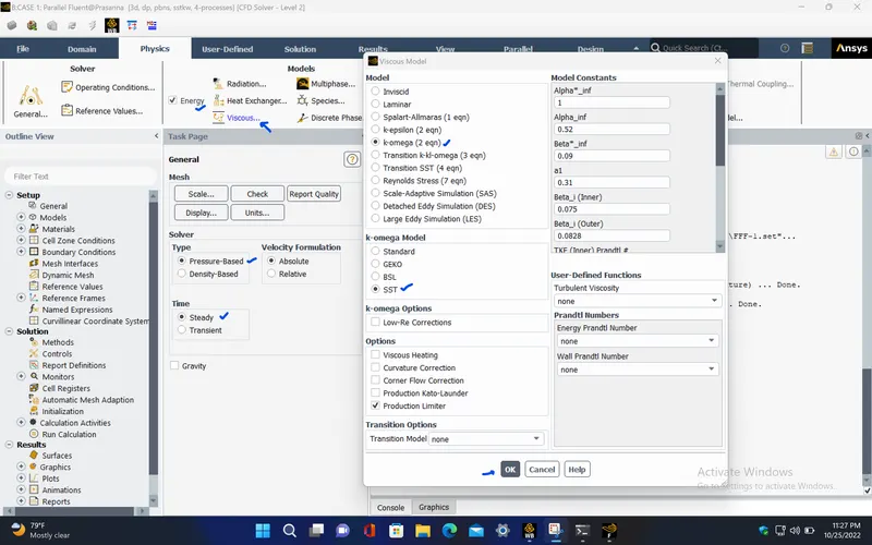
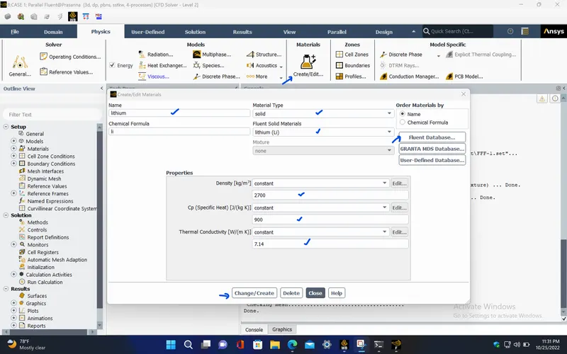
- Create the properties of Lithium-ion material by copying and changing the properties of aluminium from the fluent database for solid.
- Provide the cell zone condition of battery with heat generating source term to be 604577 W/m^3 .
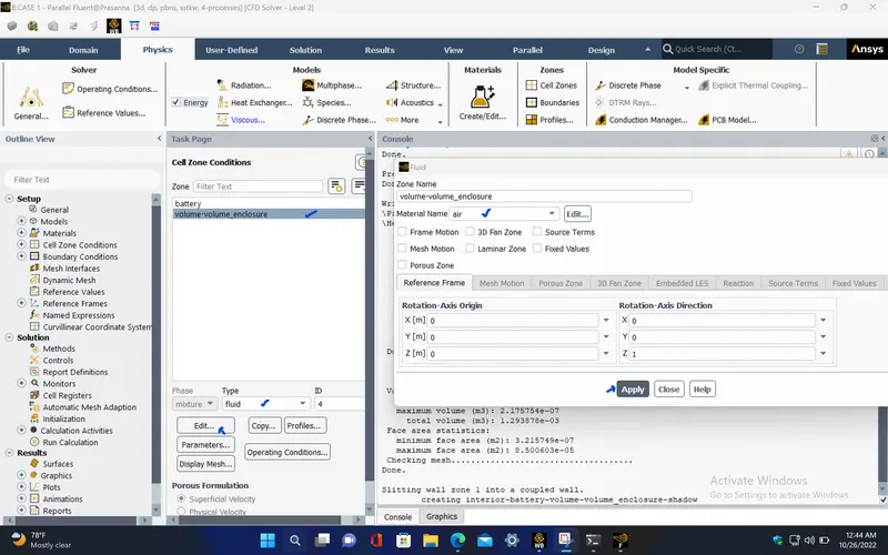
- Check if the material type for the cell zone of fluid volume is set to air.
- Give the necessary boundary conditions for the simulation. For inlet, it is taken as velocity inlet with velocity of air as 3m/s and temperature as 300K, and for outlet, it is taken as pressure outlet with atmospheric pressure.
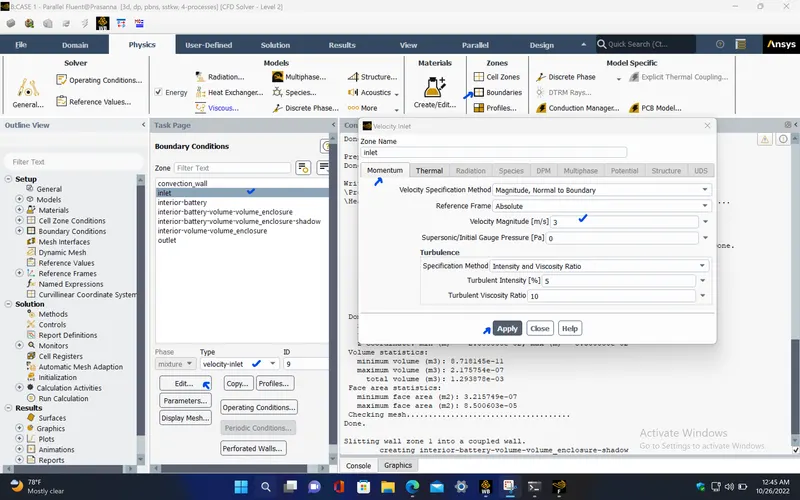
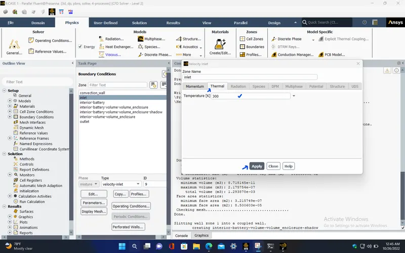
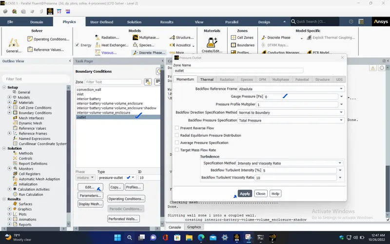
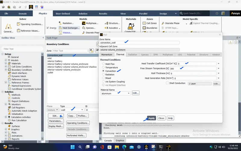
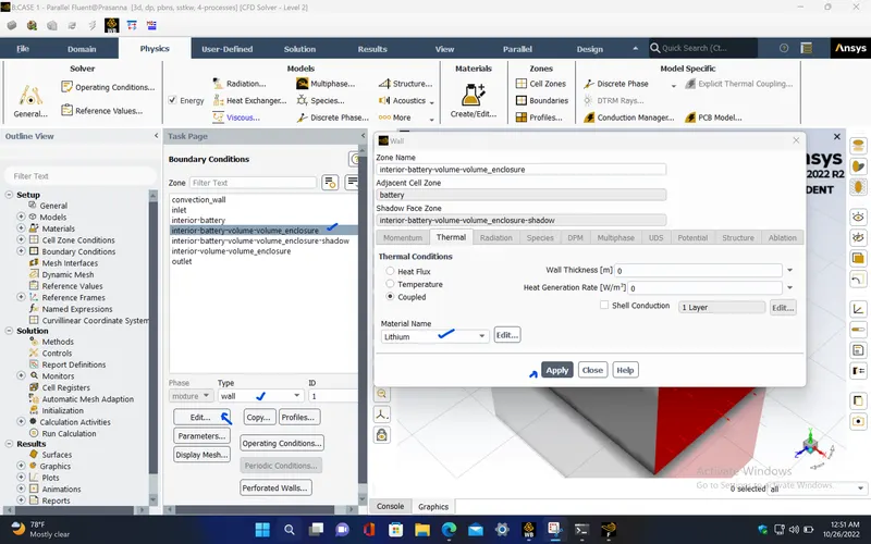
- Since the outer wall of the enclosure will also have convective heat transfer to the surrounding air, Give the boundary condition of the convection wall to be convection thermal condition with heat transfer coefficient as 5W/m^2-K and material is taken as aluminium.
- Select the Coupled scheme for pressure-velocity coupling as the solution method for this simulation.
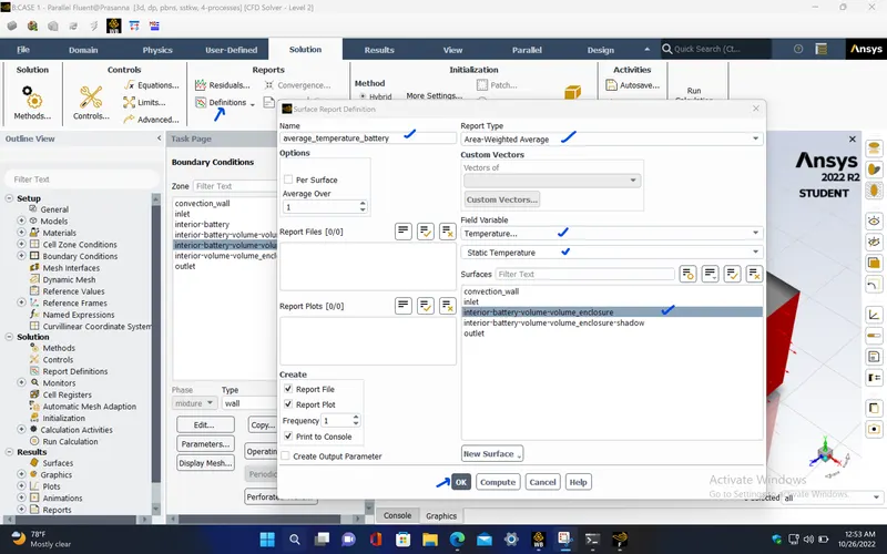
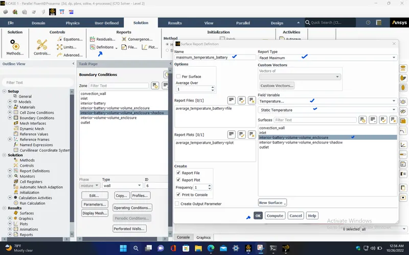
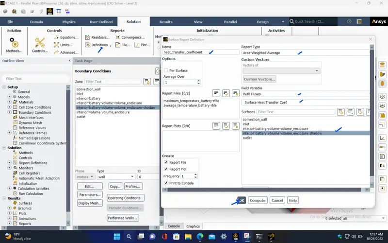
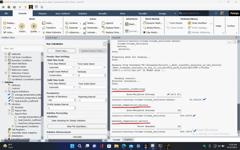
- Create report definitions for average temperature of the battery, maximum temperature of the battery and heat transfer coefficient over the battery.
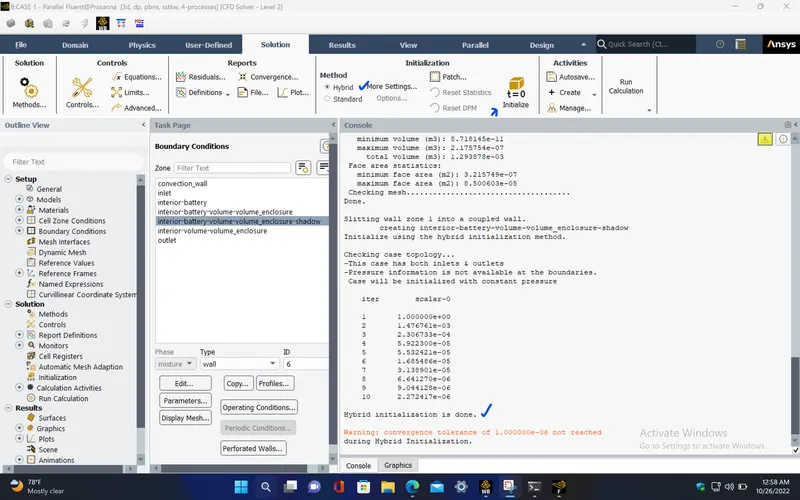
- Initialize the simulation using hybrid initialization.
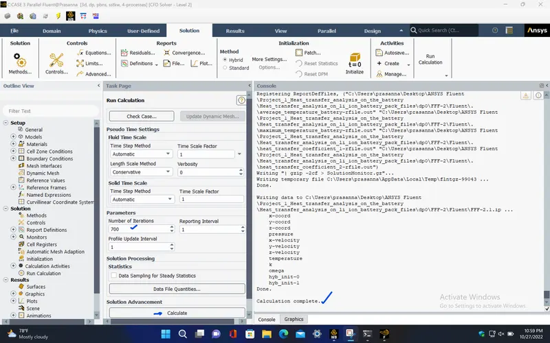
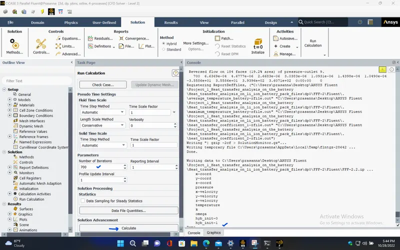
- Run the simulation for 700 iterations.
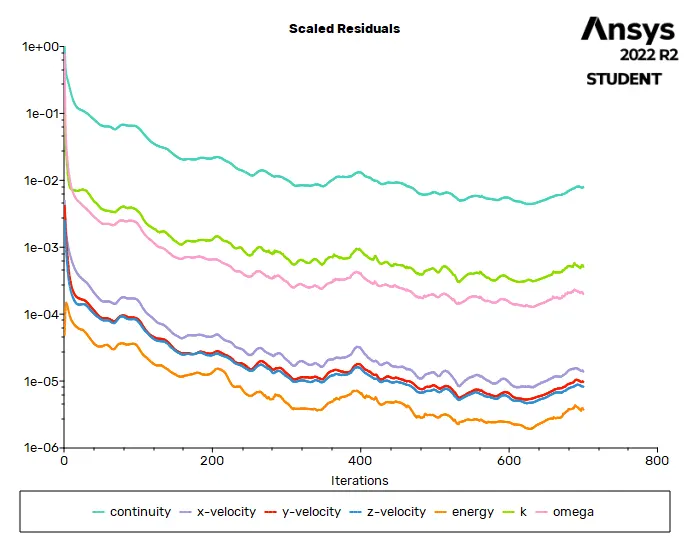
RESIDUALS PLOT :
AVERAGE TEMPERATURE PLOT (Battery) :
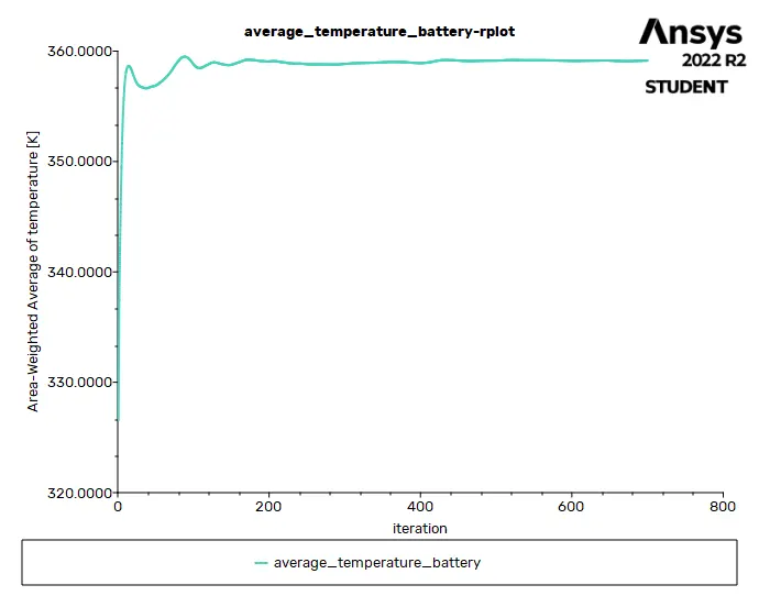
MAXIMUM TEMPERATURE PLOT (Battery) :
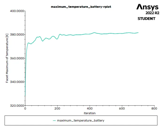
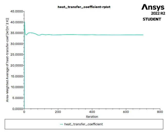
HEAT TRANSFER COEFFICIENT PLOT (over Battery) :
Solution status :
- From the above plots, we see that the solution got converged at 500th iteration since the rate at which residuals, average temperature, maximum temperature and heat transfer coefficient changes become constant over iteration.
|
Value |
Absolute Criteria |
Convergence Status |
|
|
continuity |
0.007924051 |
0.001 |
Not Converged |
|
x-velocity |
1.380776e-05 |
0.001 |
Converged |
|
y-velocity |
9.752987e-06 |
0.001 |
Converged |
|
z-velocity |
8.232296e-06 |
0.001 |
Converged |
|
energy |
3.748241e-06 |
1e-06 |
Not Converged |
|
k |
0.0005108848 |
0.001 |
Converged |
|
omega |
0.0001995334 |
0.001 |
Converged |
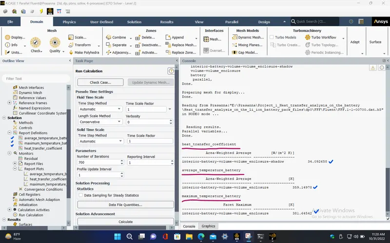
Report definitions :
|
average_temperature_battery |
359.1498 |
K |
|
maximum_temperature_battery |
381.6454 |
K |
|
heat_transfer_coefficient |
34.09266 |
W/(m^2 K) |
POST PROCESSING :
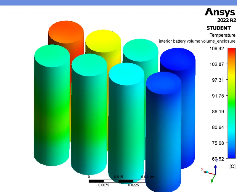
TEMPERATURE CONTOUR (Battery) :
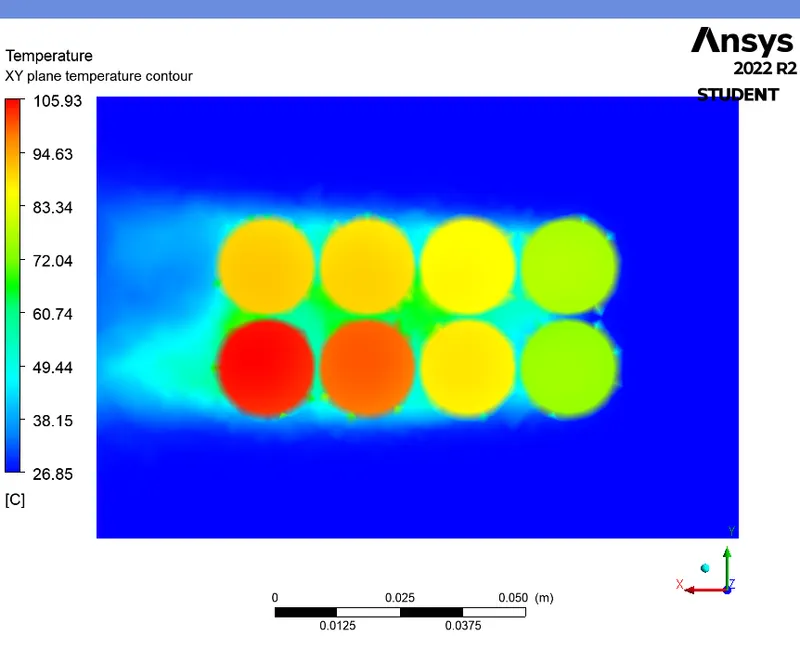
TEMPERATURE CONTOUR (XY plane) :
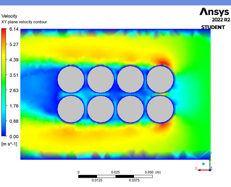
VELOCITY CONTOUR (XY plane) :
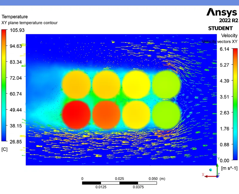
TEMPERATURE CONTOUR WITH VELOCITY VECTORS (XY plane) :
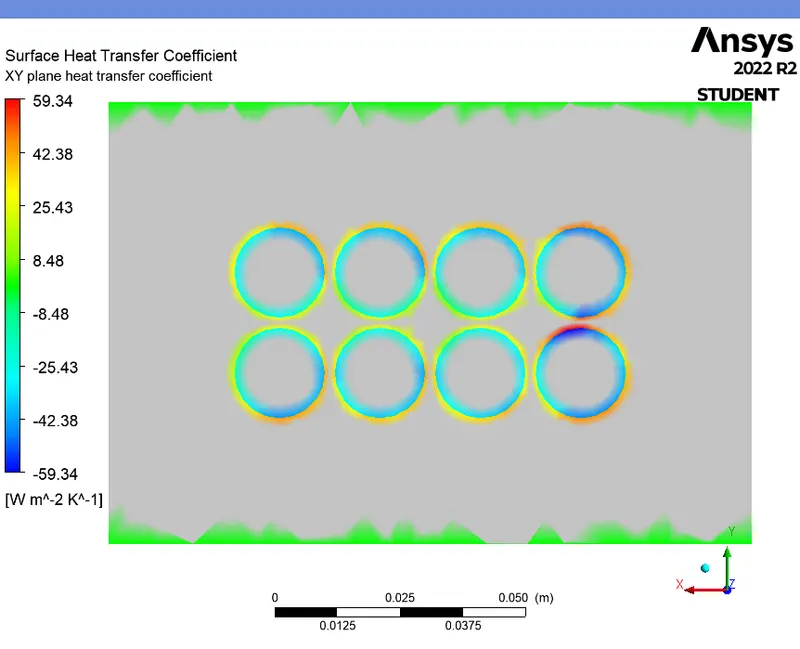
HEAT TRANSFER COEFFICIENT CONTOUR (XY plane) :
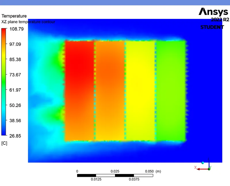
TEMPERATURE CONTOUR (XZ plane) :
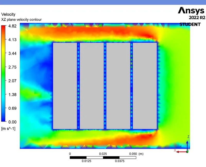
VELOCITY CONTOUR (XZ plane) :
TEMPERATURE CONTOUR WITH VELOCITY VECTORS (XZ plane) :

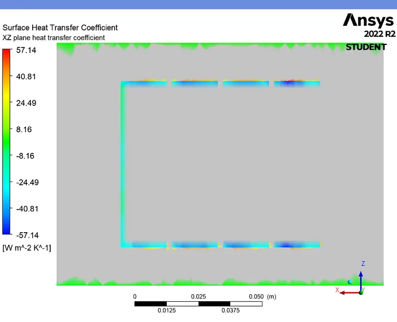
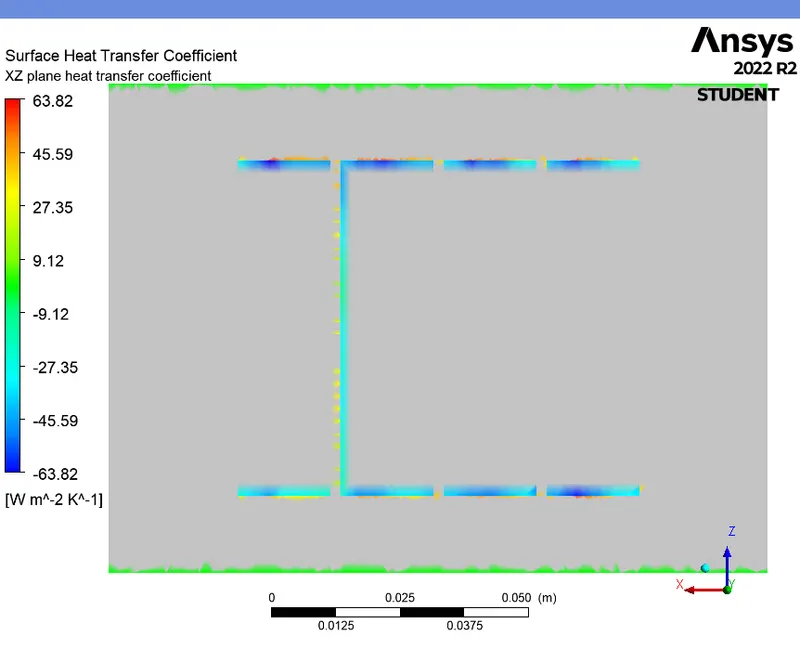
HEAT TRANSFER COEFFICIENT CONTOUR (XZ plane) :
CASE 2 (For 2mm gap and 3m/s - Fine mesh without inflation layers) :
PRE-PROCESSING :
- In this case, we take the mesh element size as 2.5 mm and generate mesh.
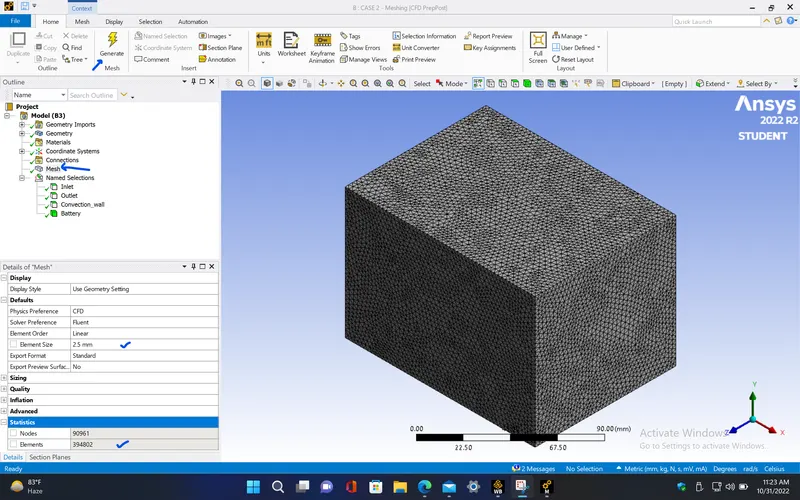
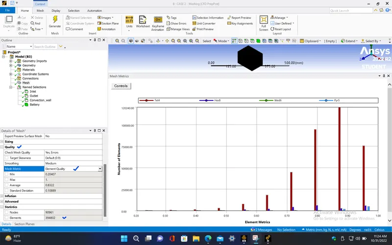
- The element quality in this case is almost 90% for most number of mesh elements. So, it can be proceeded for setup.
- Cross sectional view
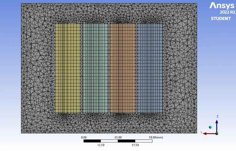
|
Cells |
Faces |
Nodes |
|
394802 |
832720 |
97813 |
SETUP AND SOLVING :
- Repeat the same procedure for the setup as discussed in the previous case.
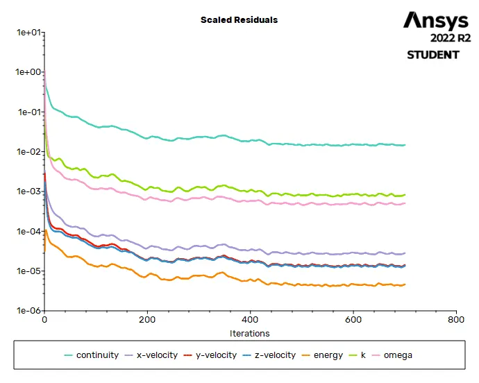
RESIDUALS PLOT :
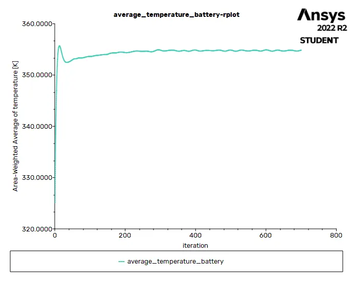
AVERAGE TEMPERATURE PLOT (Battery) :
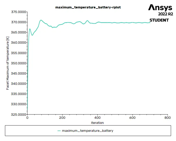
MAXIMUM TEMPERATURE PLOT (Battery) :
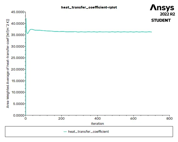
HEAT TRANSFER COEFFICIENT PLOT (over Battery) :
Solution status :
- From the above plots, we see that the solution got converged at 500th iteration since the rate at which residuals, average temperature, maximum temperature and heat transfer coefficient changes become constant over iteration.
|
Value |
Absolute Criteria |
Convergence Status |
|
|
continuity |
0.01478645 |
0.001 |
Not Converged |
|
x-velocity |
2.819623e-05 |
0.001 |
Converged |
|
y-velocity |
1.417691e-05 |
0.001 |
Converged |
|
z-velocity |
1.345576e-05 |
0.001 |
Converged |
|
energy |
4.596501e-06 |
1e-06 |
Not Converged |
|
k |
0.0008285337 |
0.001 |
Converged |
|
omega |
0.0005031071 |
0.001 |
Converged |
Report definitions :
|
average_temperature_battery |
354.8358 |
K |
|
maximum_temperature_battery |
369.7968 |
K |
|
heat_transfer_coefficient |
36.26619 |
W/(m^2 K) |
POST PROCESSING :
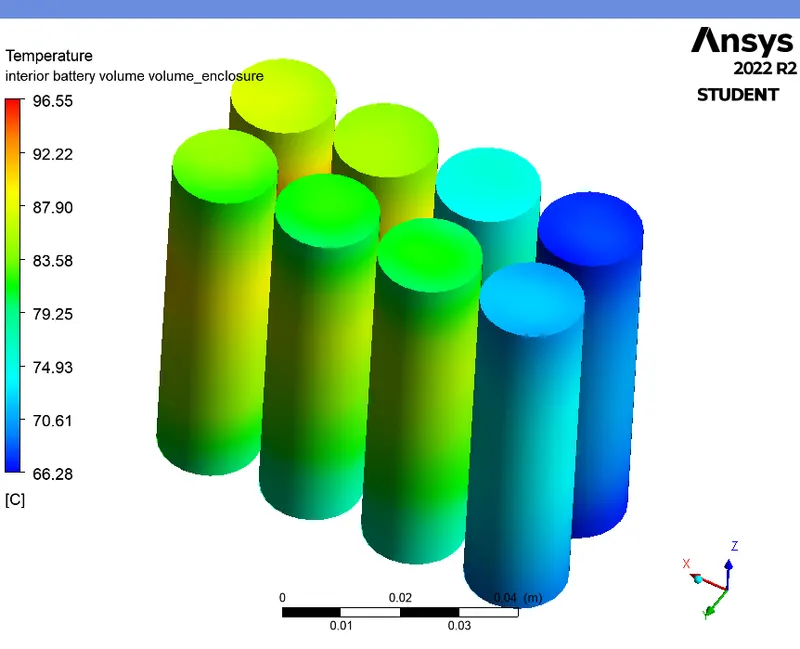
TEMPERATURE CONTOUR (Battery) :
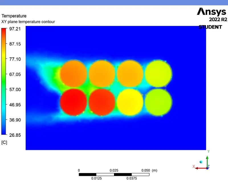
TEMPERATURE CONTOUR (XY plane) :
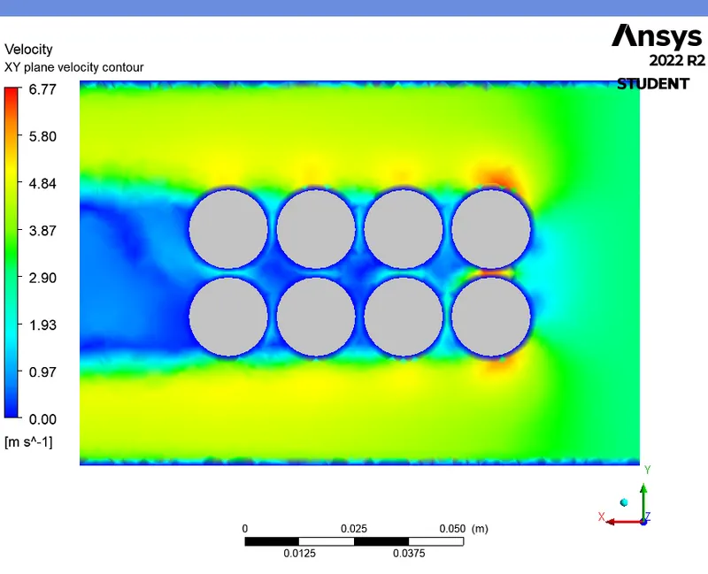
VELOCITY CONTOUR (XY plane) :
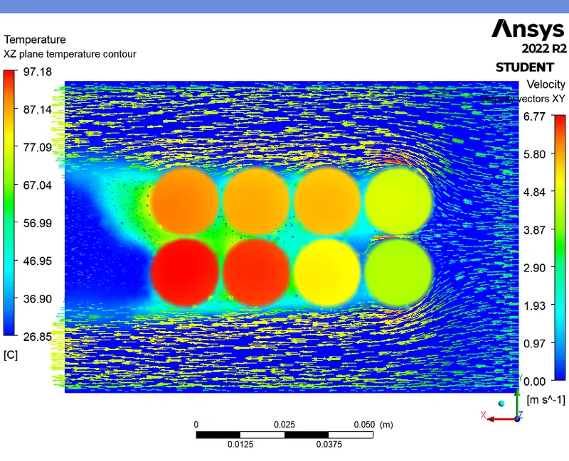
TEMPERATURE CONTOUR WITH VELOCITY VECTORS (XY plane) :
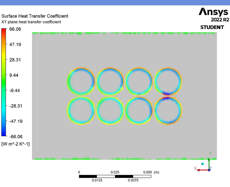
HEAT TRANSFER COEFFICIENT CONTOUR (XY plane) :
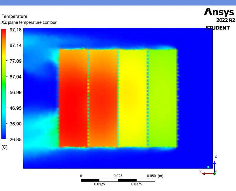
TEMPERATURE CONTOUR (XZ plane) :
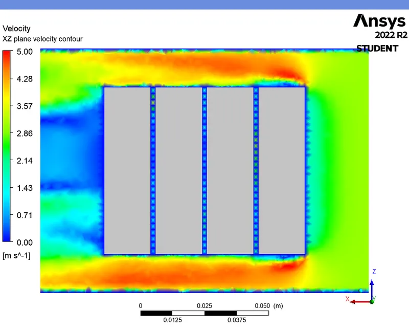
VELOCITY CONTOUR (XZ plane) :
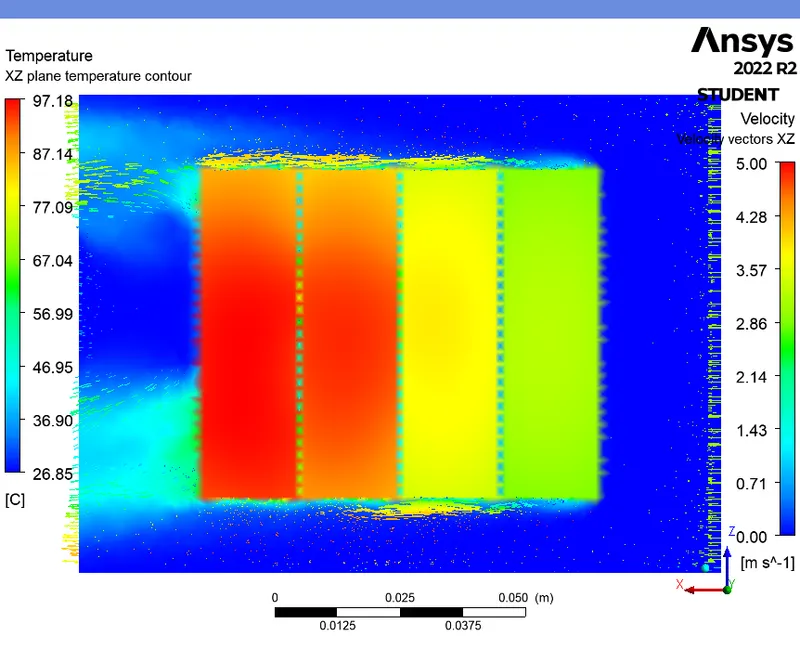
TEMPERATURE CONTOUR WITH VELOCITY VECTORS (XZ plane) :
HEAT TRANSFER COEFFICIENT CONTOUR (XZ plane) :
CASE 3 (For 2mm gap and 3m/s - Refined mesh with inflation layer) :
PRE-PROCESSING :
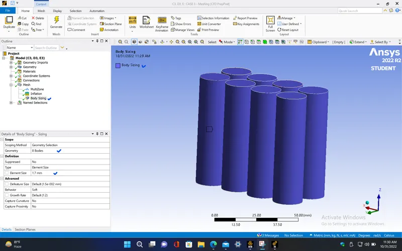
- In this case, provide sizing for the battery with mesh element size as 1.7mm.
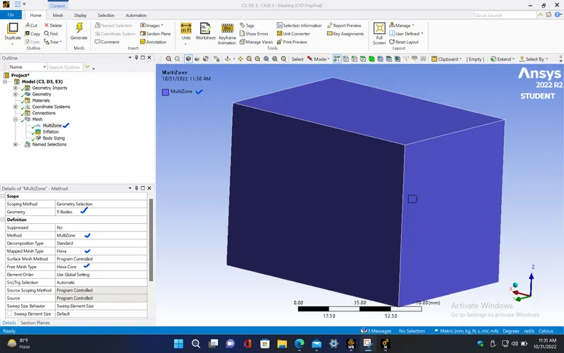
- Here, use the Multi-zone method with free mesh type as Hexa core which will create hexahedral mesh elements at the inner core regions of the fluid domain and battery, and tetrahedral elements near to the wall surfaces to capture the surface properly. This will help to reduce the number of mesh elements while giving the accurate results.
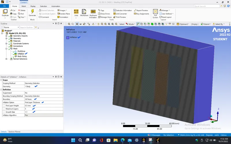
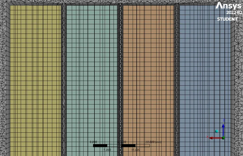
- Create inflation layers near to the battery surface with first layer thickness as 0.3mm and number of layers as 5 with growth rate of 1.1 . This will be useful in capturing the viscous layer near to the boundary of the battery where the velocity gradient is large.
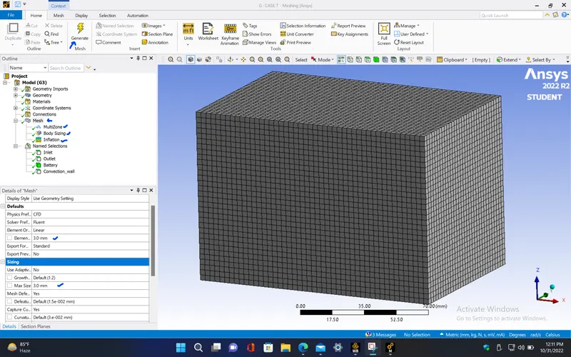
- Generate mesh by giving the mesh element size as 3mm and maximum mesh size also given as 3mm to get the uniform mesh elements.
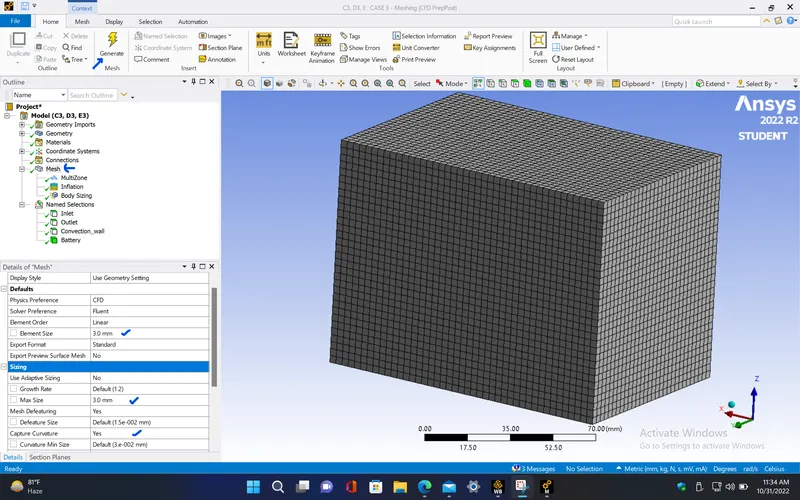
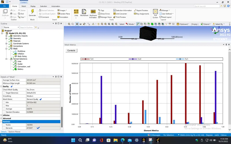
- Here, we can see that the element quality is average compared to previous cases since we have created the inflation layer but since most the mesh elements have quality above 50% mesh quality, this can be proceeded for setup.
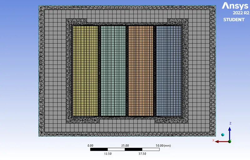
- Cross sectional view
- Inflation layers
|
Cells |
Faces |
Nodes |
|
415507 |
988548 |
196187 |
|
Name |
Type |
Min Orthogonal Quality |
Max Aspect Ratio |
|
volume-volume_enclosure |
Mixed Cell |
0.10833002 |
68.004107 |
|
battery |
Hex Cell |
0.87975139 |
2.8041767 |
SETUP AND SOLVING :
- Repeat the same procedure as discussed in the previous case for this simulation.
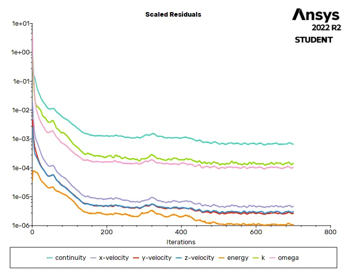
RESIDUALS PLOT :
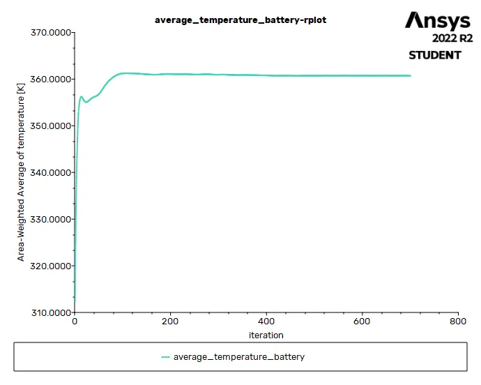
AVERAGE TEMPERATURE PLOT (Battery) :
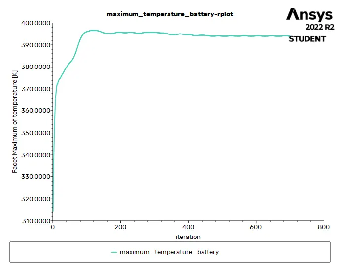
MAXIMUM TEMPERATURE PLOT (Battery) :
HEAT TRANSFER COEFFICIENT PLOT (over Battery) :
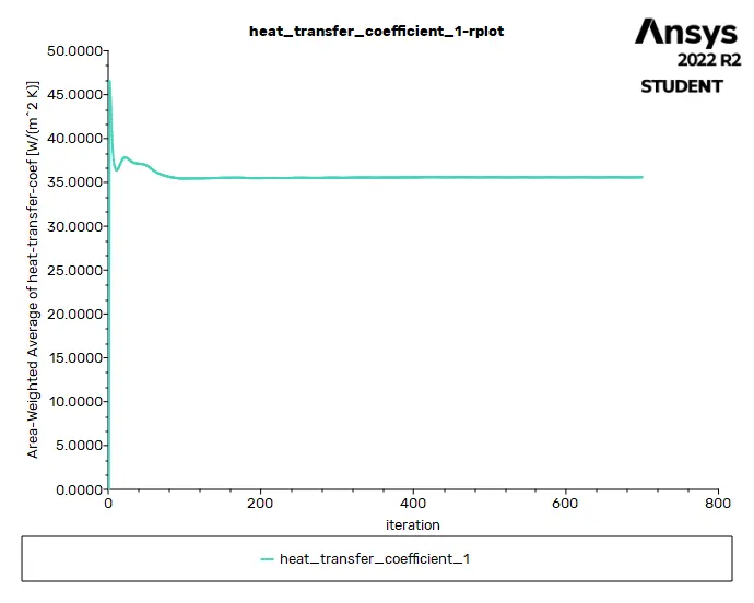
Solution status :
- From the above plots, we see that the solution got converged at 500th iteration since the rate at which residuals, average temperature, maximum temperature and heat transfer coefficient changes become constant over iteration.
|
Value |
Absolute Criteria |
Convergence Status |
|
|
continuity |
0.0006636928 |
0.001 |
Converged |
|
x-velocity |
4.677682e-06 |
0.001 |
Converged |
|
y-velocity |
2.668286e-06 |
0.001 |
Converged |
|
z-velocity |
3.038325e-06 |
0.001 |
Converged |
|
energy |
1.093079e-06 |
1e-06 |
Not Converged |
|
k |
0.0001439756 |
0.001 |
Converged |
|
omega |
0.0001048975 |
0.001 |
Converged |
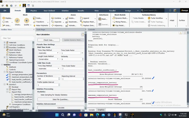
Report definitions :
|
average_temperature_battery |
360.7065 |
K |
|
maximum_temperature_battery |
393.9565 |
K |
|
heat_transfer_coefficient_1 |
35.58587 |
W/(m^2 K) |
POST PROCESSING :
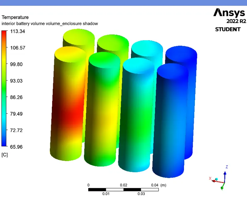
TEMPERATURE CONTOUR (Battery) :
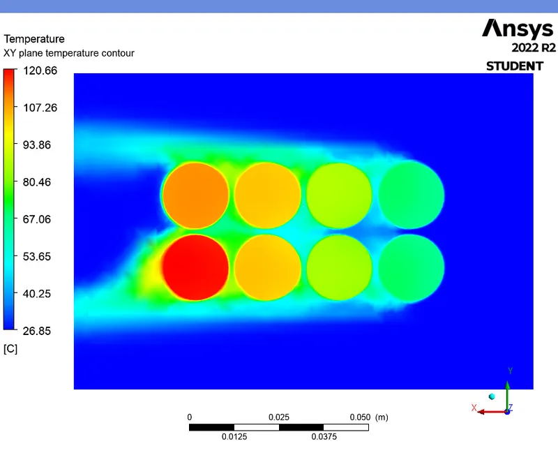
TEMPERATURE CONTOUR (XY plane) :
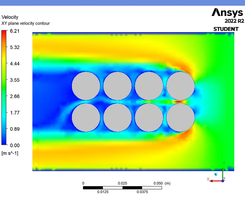
VELOCITY CONTOUR (XY plane) :
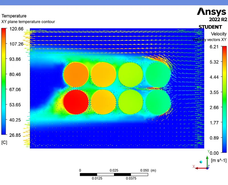
TEMPERATURE CONTOUR WITH VELOCITY VECTORS (XY plane) :
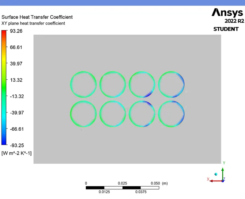
HEAT TRANSFER COEFFICIENT CONTOUR (XY plane) :
TEMPERATURE CONTOUR (XZ plane) :

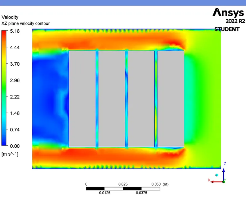
VELOCITY CONTOUR (XZ plane) :
TEMPERATURE CONTOUR WITH VELOCITY VECTORS (XZ plane) :
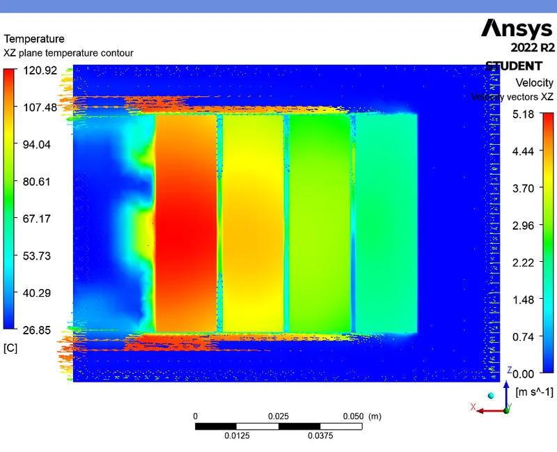
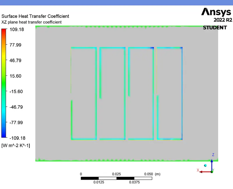
HEAT TRANSFER COEFFICIENT CONTOUR (XZ plane) :
Mesh independency study :
- From the above contours for the three different mesh size, we can see that, the contours are more distorted near the battery surface in the Case-1 and Case-2 since the boundary layers are not created for those cases which gives in less accurate results compared to Case-3. Since the boundary layers are created near the battery surface in Case-3, the surface of the battery is well captured which gives a clear contour plots.
|
MESH ELEMENT SIZE |
NUMBER OF MESH ELEMENTS |
INLET VELOCITY OF AIR ('m/s') |
GAP BETWEEN BATTERIES ('mm') |
AVERAGE TEMPERATURE OF THE BATTERY ('K') |
MAXIMUM TEMPERATURE OF THE BATTERY ('K') |
HEAT TRANSFER COEFFICIENT OVER THE BATTERY ('W/m^2-K') |
|
|
CASE 1 |
Baseline mesh (9 mm) |
161823 |
3 |
2 |
359.1498 |
381.6454 |
34.09266 |
|
CASE 2 |
Fine mesh (2.5mm, without inflation layers) |
394802 |
3 |
2 |
354.8358 |
369.7968 |
36.26619 |
|
CASE 3 |
Refined mesh (3mm, with inflation layers) |
415507 |
3 |
2 |
360.7065 |
393.9565 |
35.58587 |
- From the above table, we can see that, the Case-3 with inflation layers gives more accurate results compared to the other cases. So, we choose the Refined mesh in Case-3 for the upcoming simulations to get accurate results.
CASE 4 (For 2mm gap and 5m/s - Steady state) :
SETUP AND SOLVING :
- In this case, change the inlet velocity of air as 5m/s and follow the same procedure as discussed in the previous case.
Boundary conditions :
|
inlet |
|
|
Velocity Specification Method |
Magnitude, Normal to Boundary |
|
Reference Frame |
Absolute |
|
Velocity Magnitude [m/s] |
5 |
|
Supersonic/Initial Gauge Pressure [Pa] |
0 |
|
Temperature [K] |
300 |
|
outlet |
|
|
Backflow Reference Frame |
Absolute |
|
Gauge Pressure [Pa] |
0 |
|
Backflow Total Temperature [K] |
300 |
|
Backflow Direction Specification Method |
Normal to Boundary |
|
Wall |
|
|
interior-battery-volume-volume_enclosure-shadow |
|
|
Material Name |
lithium |
|
Thermal BC Type |
Coupled |
|
Wall Motion |
Stationary Wall |
|
Shear Boundary Condition |
No Slip |
|
interior-battery-volume-volume_enclosure |
|
|
Material Name |
lithium |
|
Thermal BC Type |
Coupled |
|
convection_wall |
|
|
Material Name |
aluminum |
|
Thermal BC Type |
Convection |
|
Convective Heat Transfer Coefficient [W/(m^2 K)] |
5 |
|
Free Stream Temperature [K] |
300 |
|
Wall Motion |
Stationary Wall |
|
Shear Boundary Condition |
No Slip |
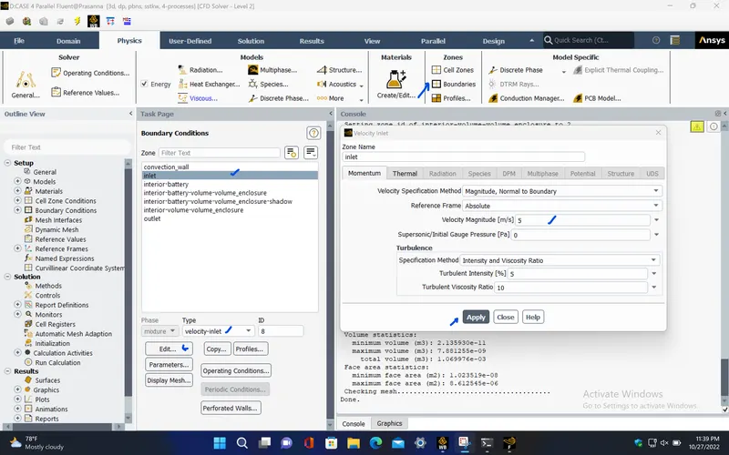
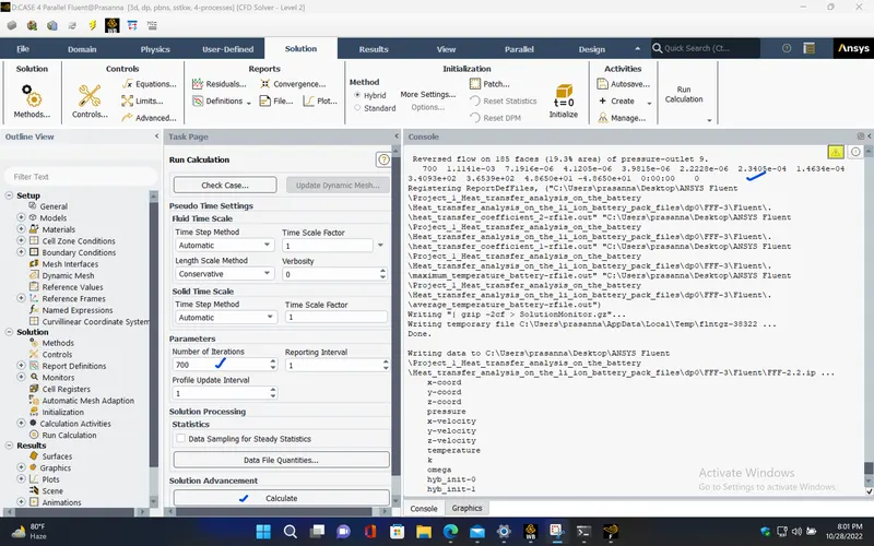
RESIDUALS PLOT :
AVERAGE TEMPERATURE PLOT (Battery) :
MAXIMUM TEMPERATURE PLOT (Battery) :
HEAT TRANSFER COEFFICIENT PLOT (over Battery) :
Solution status :
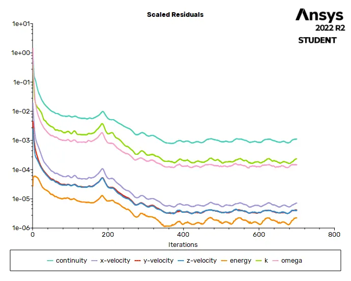
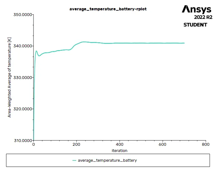
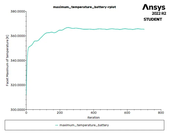
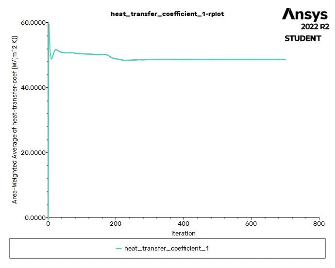
- From the above plots, we see that the solution got converged at 600th iteration since the rate at which residuals, average temperature, maximum temperature and heat transfer coefficient changes become constant over iteration.
|
Value |
Absolute Criteria |
Convergence Status |
|
|
continuity |
0.001114085 |
0.001 |
Not Converged |
|
x-velocity |
7.191598e-06 |
0.001 |
Converged |
|
y-velocity |
4.120537e-06 |
0.001 |
Converged |
|
z-velocity |
3.981547e-06 |
0.001 |
Converged |
|
energy |
2.222791e-06 |
1e-06 |
Not Converged |
|
k |
0.0002340466 |
0.001 |
Converged |
|
omega |
0.0001463394 |
0.001 |
Converged |
Report definitions :
|
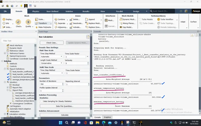
heat_transfer_coefficient_1 |
48.64977 |
W/(m^2 K) |
|
maximum_temperature_battery |
365.388 |
K |
|
average_temperature_battery |
340.9346 |
K |
POST PROCESSING :
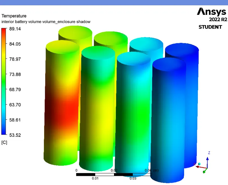
TEMPERATURE CONTOUR (Battery) :
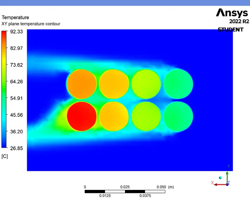
TEMPERATURE CONTOUR (XY plane) :
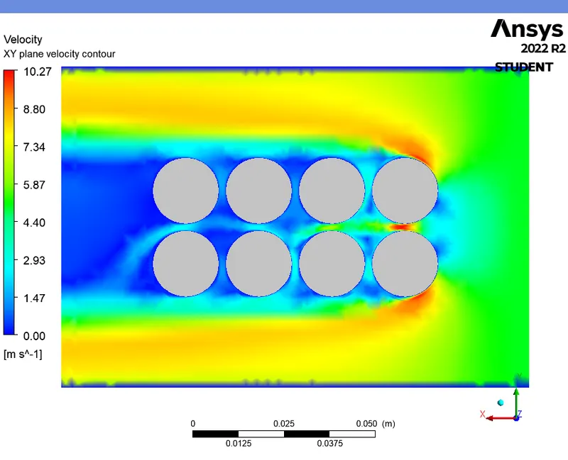
VELOCITY CONTOUR (XY plane) :
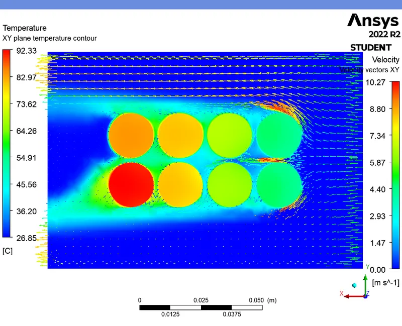
TEMPERATURE CONTOUR WITH VELOCITY VECTORS (XY plane) :
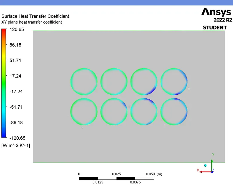
HEAT TRANSFER COEFFICIENT CONTOUR (XY plane) :
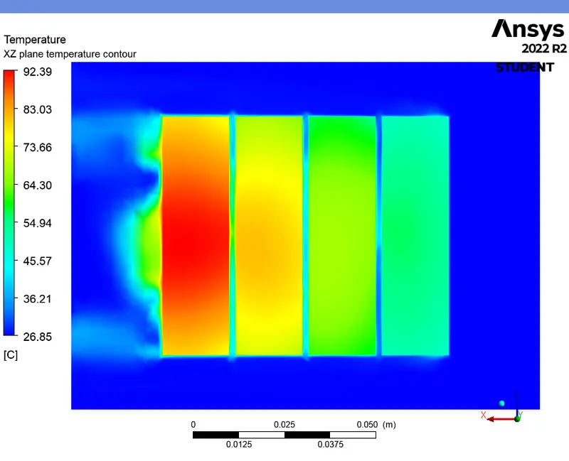
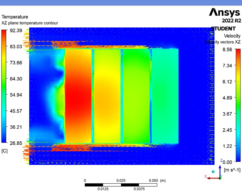
TEMPERATURE CONTOUR (XZ plane) :
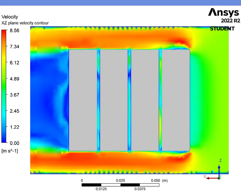
VELOCITY CONTOUR (XZ plane) :
TEMPERATURE CONTOUR WITH VELOCITY VECTORS (XZ plane) :
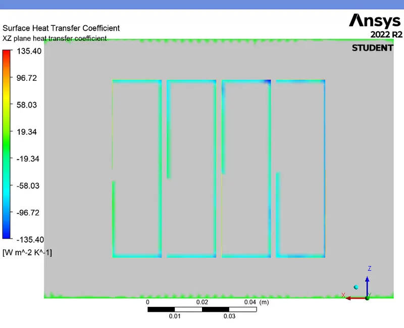
HEAT TRANSFER COEFFICIENT CONTOUR (XZ plane) :
CASE 5 (For 2mm gap and 10m/s - Steady state) :
SETUP AND SOLVING :
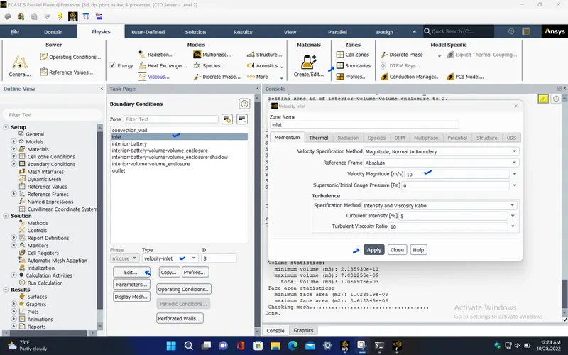
- In this case, change the inlet velocity of air as 10m/s and follow the same procedure as discussed in the previous case.
Boundary conditions :
|
inlet |
|
|
Velocity Specification Method |
Magnitude, Normal to Boundary |
|
Reference Frame |
Absolute |
|
Velocity Magnitude [m/s] |
10 |
|
Supersonic/Initial Gauge Pressure [Pa] |
0 |
|
Temperature [K] |
300 |
|
outlet |
|
|
Backflow Reference Frame |
Absolute |
|
Gauge Pressure [Pa] |
0 |
|
Backflow Total Temperature [K] |
300 |
|
Backflow Direction Specification Method |
Normal to Boundary |
|
Wall |
|
|
interior-battery-volume-volume_enclosure-shadow |
|
|
Material Name |
lithium |
|
Thermal BC Type |
Coupled |
|
Wall Motion |
Stationary Wall |
|
Shear Boundary Condition |
No Slip |
|
interior-battery-volume-volume_enclosure |
|
|
Material Name |
lithium |
|
Thermal BC Type |
Coupled |
|
convection_wall |
|
|
Material Name |
aluminum |
|
Thermal BC Type |
Convection |
|
Convective Heat Transfer Coefficient [W/(m^2 K)] |
5 |
|
Free Stream Temperature [K] |
300 |
|
Wall Motion |
Stationary Wall |
|
Shear Boundary Condition |
No Slip |
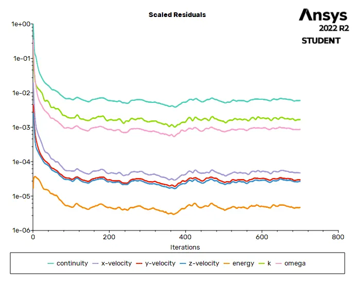
RESIDUALS PLOT :
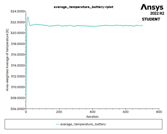
AVERAGE TEMPERATURE PLOT (Battery) :
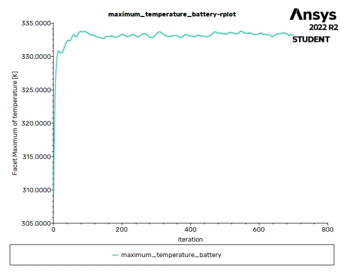
MAXIMUM TEMPERATURE PLOT (Battery) :
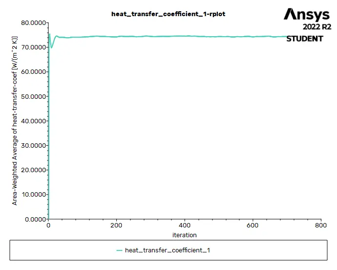
HEAT TRANSFER COEFFICIENT PLOT (over Battery) :
Solution status :
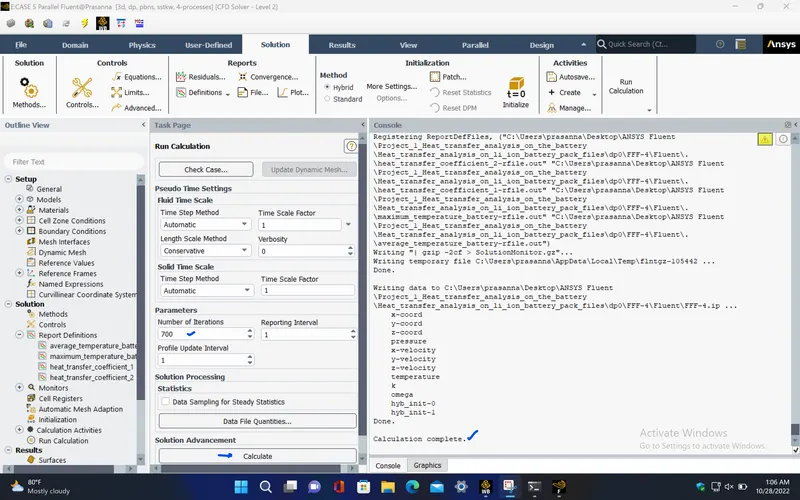
- From the above plots, we see that the solution got converged at 600th iteration since the rate at which residuals, average temperature, maximum temperature and heat transfer coefficient changes become constant over iteration.
|
Value |
Absolute Criteria |
Convergence Status |
|
|
continuity |
0.005973904 |
0.001 |
Not Converged |
|
x-velocity |
4.688677e-05 |
0.001 |
Converged |
|
y-velocity |
2.966589e-05 |
0.001 |
Converged |
|
z-velocity |
2.683298e-05 |
0.001 |
Converged |
|
energy |
4.71754e-06 |
1e-06 |
Not Converged |
|
k |
0.001660747 |
0.001 |
Not Converged |
|
omega |
0.0008611094 |
0.001 |
Converged |
Report definitions :
|
heat_transfer_coefficient_1 |
74.36751 |
W/(m^2 K) |
|
maximum_temperature_battery |
333.1902 |
K |
|
average_temperature_battery |
321.3586 |
K |
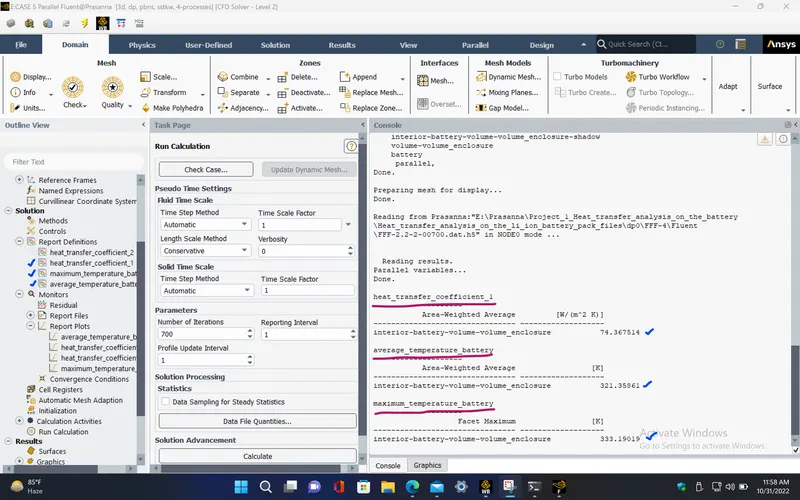
POST PROCESSING :
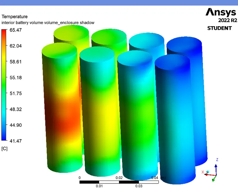
TEMPERATURE CONTOUR (Battery) :
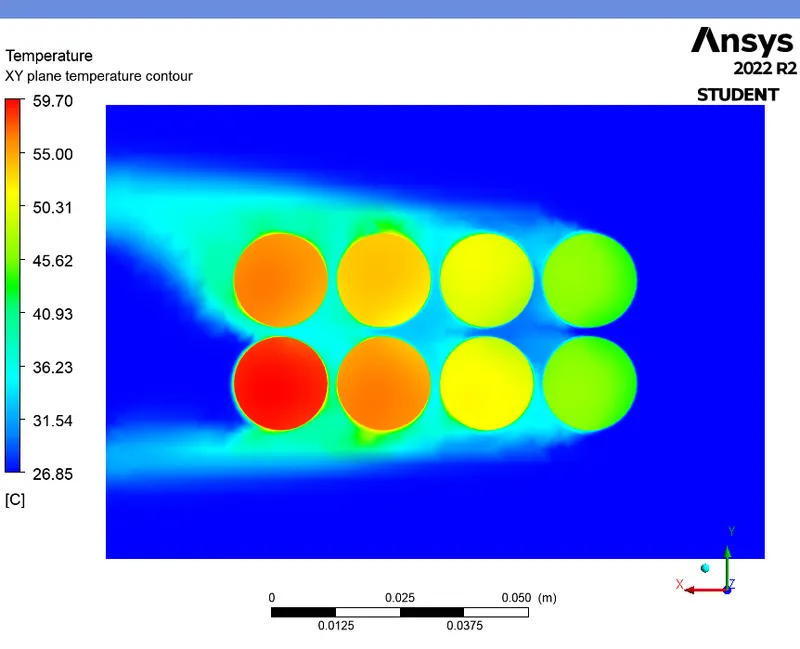
TEMPERATURE CONTOUR (XY plane) :
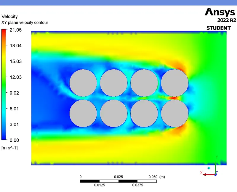
VELOCITY CONTOUR (XY plane) :
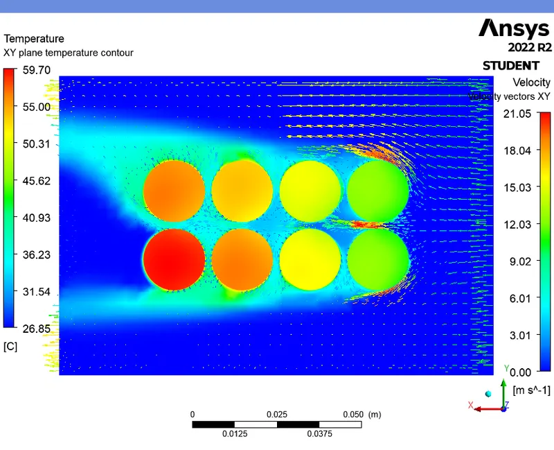
TEMPERATURE CONTOUR WITH VELOCITY VECTORS (XY plane) :
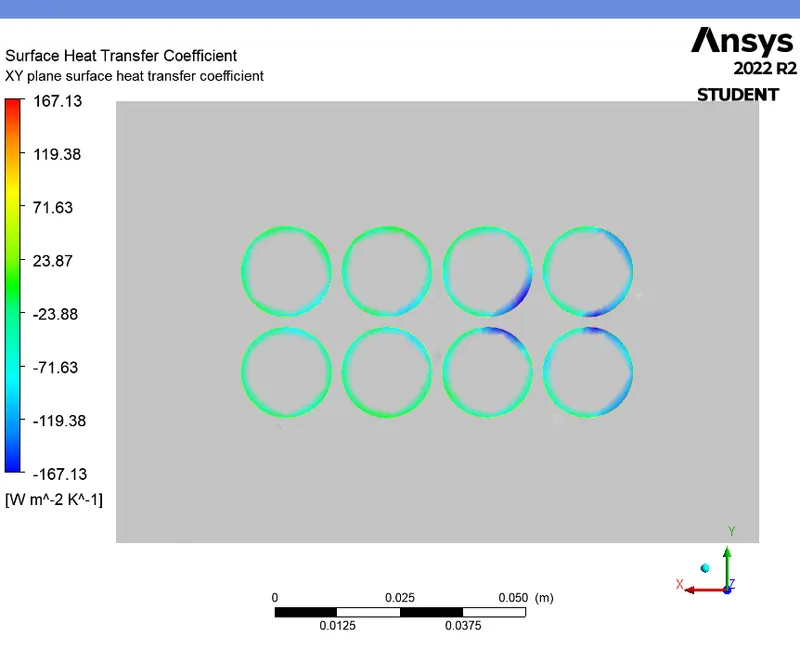
HEAT TRANSFER COEFFICIENT CONTOUR (XY plane) :
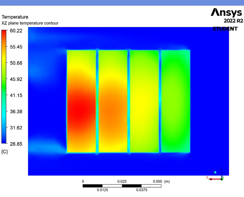
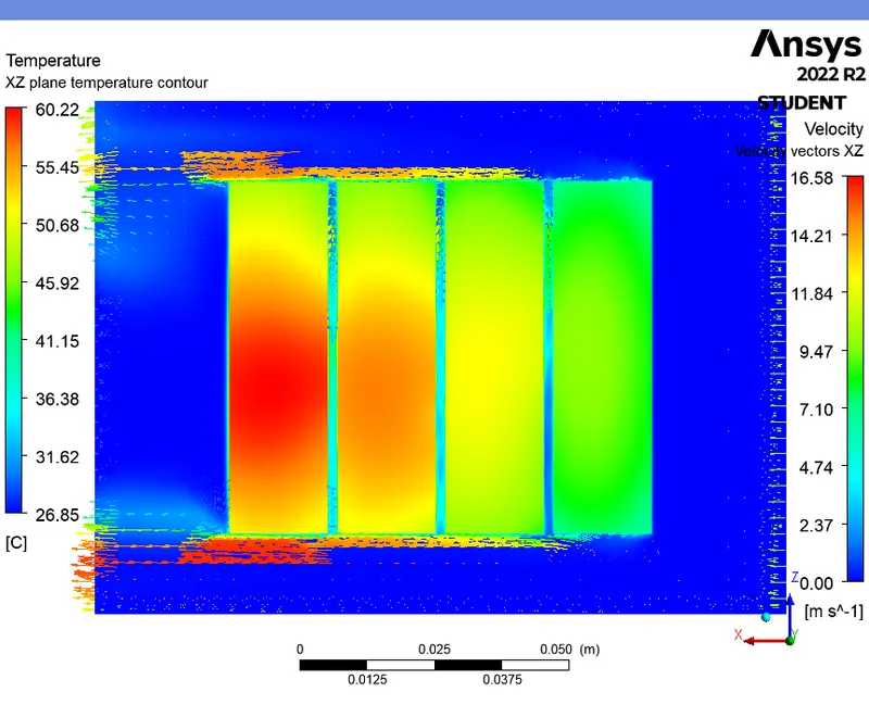
TEMPERATURE CONTOUR (XZ plane) :
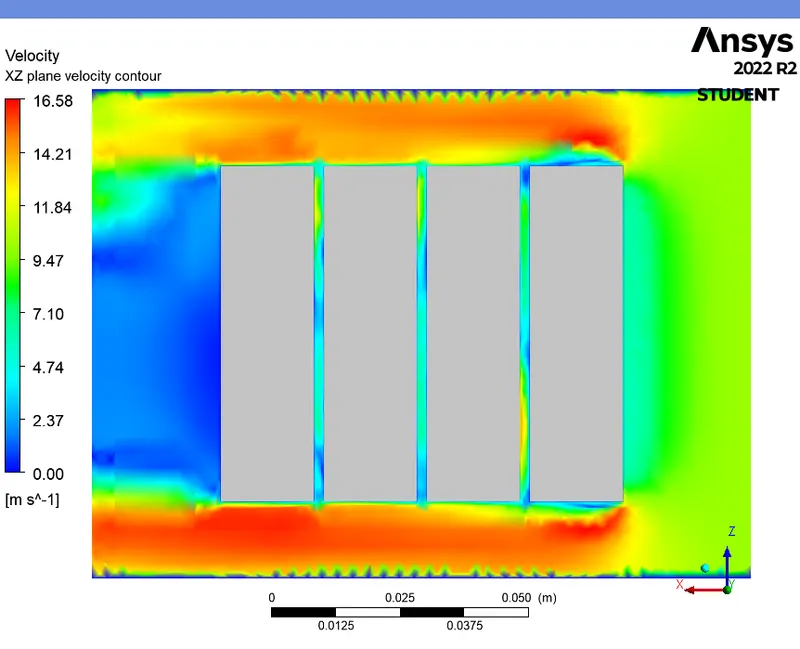
VELOCITY CONTOUR (XZ plane) :
TEMPERATURE CONTOUR WITH VELOCITY VECTORS (XZ plane) :
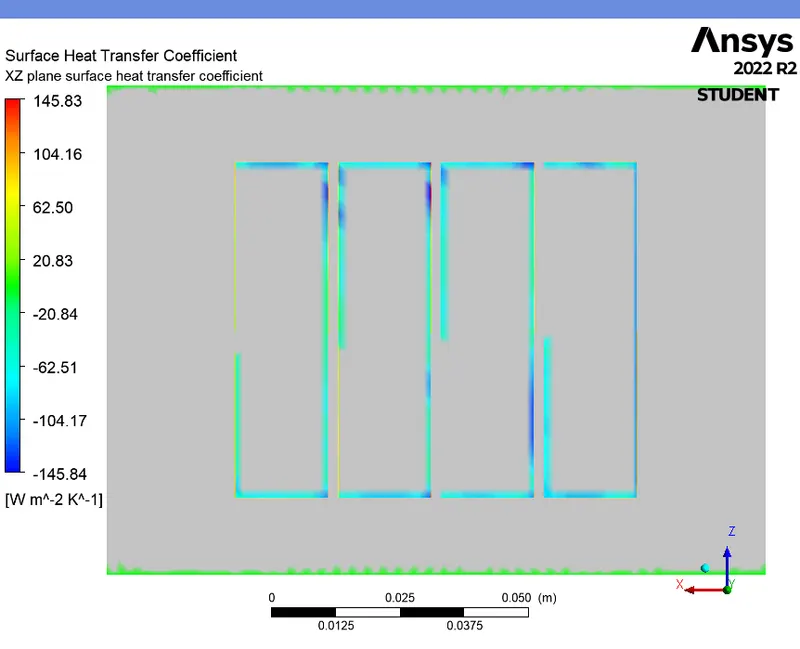
HEAT TRANSFER COEFFICIENT CONTOUR (XZ plane) :
CASE 6 (For 4mm gap and 10m/s - Steady state) :
- From the above cases, we can see that the Case-5 with 10m/s velocity gives less temperature for battery compared to others cases. So, this velocity is taken for this simulation
PRE-PROCESSING :
- Here, change the space between the batteries to 4mm and repeat the same procedure as discussed in the previous cases.
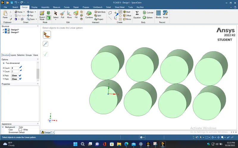
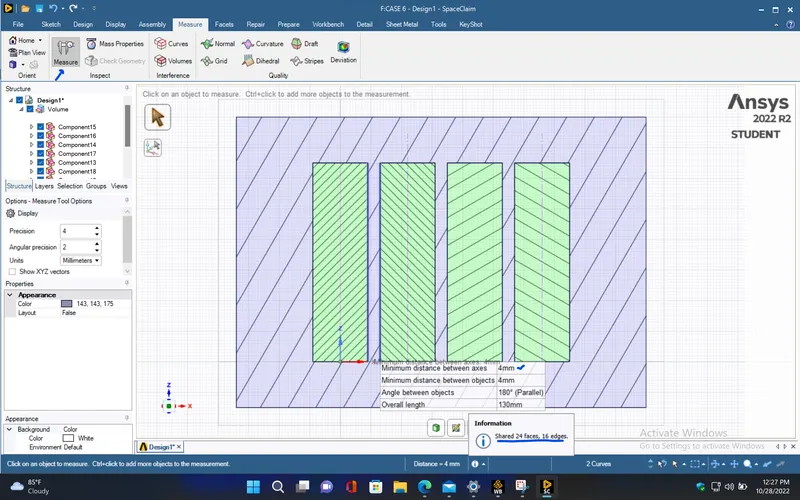
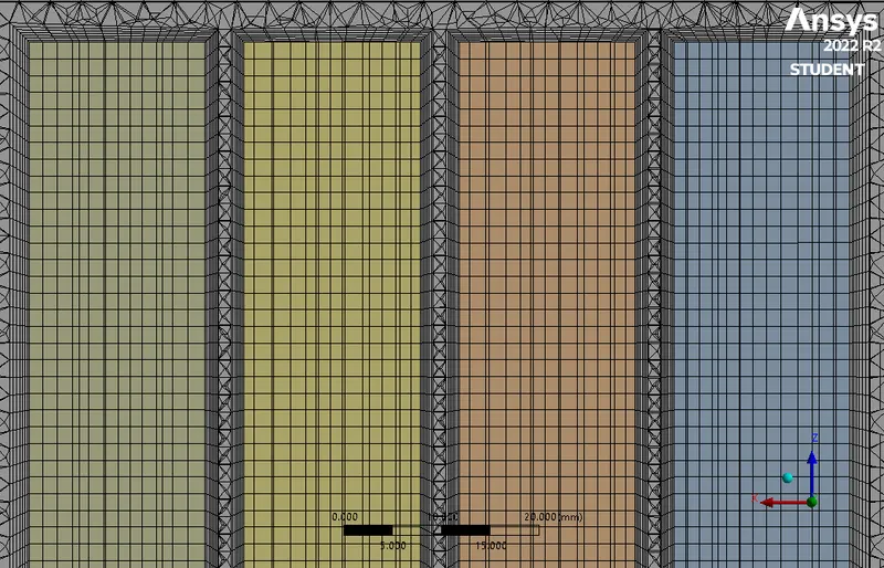
- Create inflation layers with first layer thickness as 0.3mm and number of layers as 7 since the space between the batteries is increased.
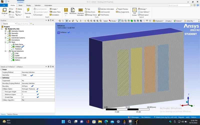
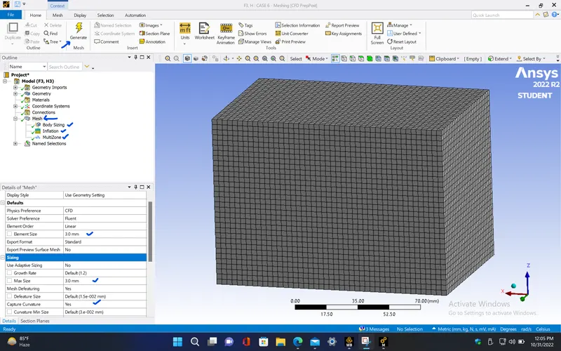
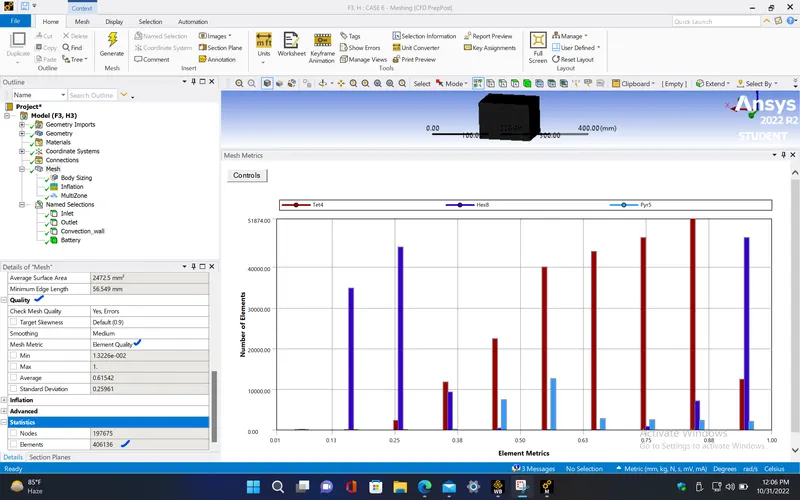
- Cross sectional view
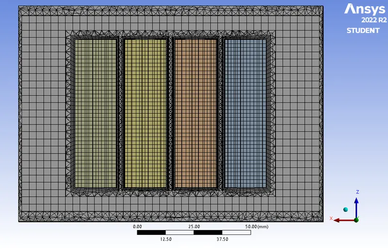
- Inflation layers
|
Cells |
Faces |
Nodes |
|
406136 |
988212 |
210471 |
|
Name |
Type |
Min Orthogonal Quality |
Max Aspect Ratio |
|
volume-volume_enclosure |
Mixed Cell |
0.059501137 |
209.15539 |
|
battery |
Hex Cell |
0.9036489 |
2.8163736 |
SETUP AND SOLVING :
- Repeat the same procedure as in the previous case for this setup.
Boundary conditions :
|
inlet |
|
|
Velocity Specification Method |
Magnitude, Normal to Boundary |
|
Reference Frame |
Absolute |
|
Velocity Magnitude [m/s] |
10 |
|
Supersonic/Initial Gauge Pressure [Pa] |
0 |
|
Temperature [K] |
300 |
|
outlet |
|
|
Backflow Reference Frame |
Absolute |
|
Gauge Pressure [Pa] |
0 |
|
Backflow Total Temperature [K] |
300 |
|
Backflow Direction Specification Method |
Normal to Boundary |
|
Wall |
|
|
interior-battery-volume-volume_enclosure-shadow |
|
|
Material Name |
lithium |
|
Thermal BC Type |
Coupled |
|
Wall Motion |
Stationary Wall |
|
Shear Boundary Condition |
No Slip |
|
interior-battery-volume-volume_enclosure |
|
|
Material Name |
lithium |
|
Thermal BC Type |
Coupled |
|
convection_wall |
|
|
Material Name |
aluminum |
|
Thermal BC Type |
Convection |
|
Convective Heat Transfer Coefficient [W/(m^2 K)] |
5 |
|
Free Stream Temperature [K] |
300 |
|
Wall Motion |
Stationary Wall |
|
Shear Boundary Condition |
No Slip |
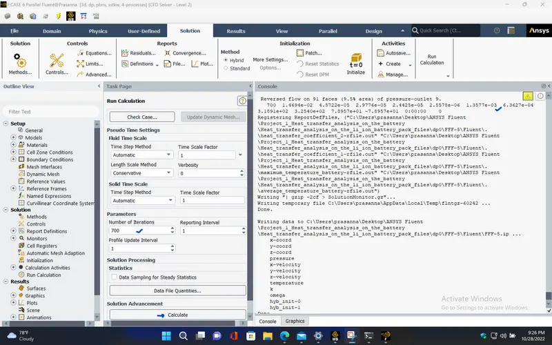
RESIDUALS PLOT :
AVERAGE TEMPERATURE PLOT (Battery) :
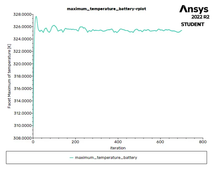
MAXIMUM TEMPERATURE PLOT (Battery) :
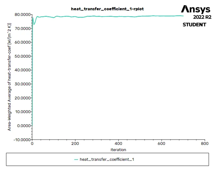
HEAT TRANSFER COEFFICIENT PLOT (over Battery) :
Solution status :
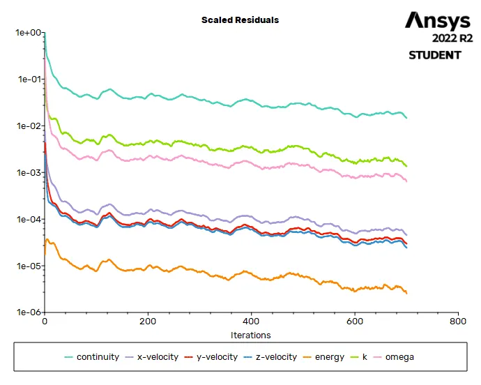
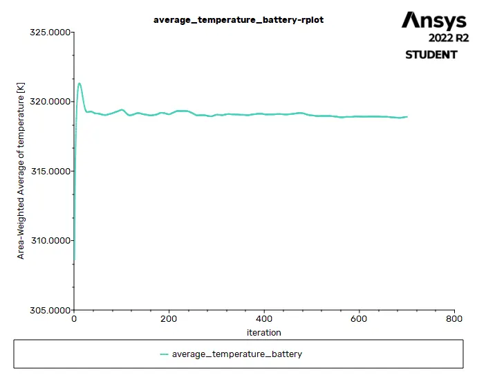
- From the above plots, we see that the solution got converged at 600th iteration since the rate at which residuals, average temperature, maximum temperature and heat transfer coefficient changes become constant over iteration.
|
Value |
Absolute Criteria |
Convergence Status |
|
|
continuity |
0.01469427 |
0.001 |
Not Converged |
|
x-velocity |
4.572214e-05 |
0.001 |
Converged |
|
y-velocity |
2.977623e-05 |
0.001 |
Converged |
|
z-velocity |
2.442496e-05 |
0.001 |
Converged |
|
energy |
2.557813e-06 |
1e-06 |
Not Converged |
|
k |
0.001357736 |
0.001 |
Not Converged |
|
omega |
0.0006362682 |
0.001 |
Converged |
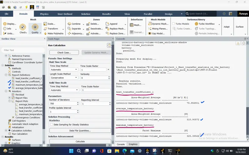
Report definitions :
|
heat_transfer_coefficient_1 |
78.9569 |
W/(m^2 K) |
|
maximum_temperature_battery |
325.3957 |
K |
|
average_temperature_battery |
318.9057 |
K |
POST PROCESSING :
TEMPERATURE CONTOUR (Battery) :
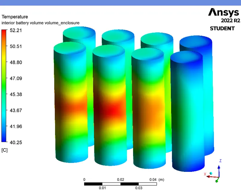
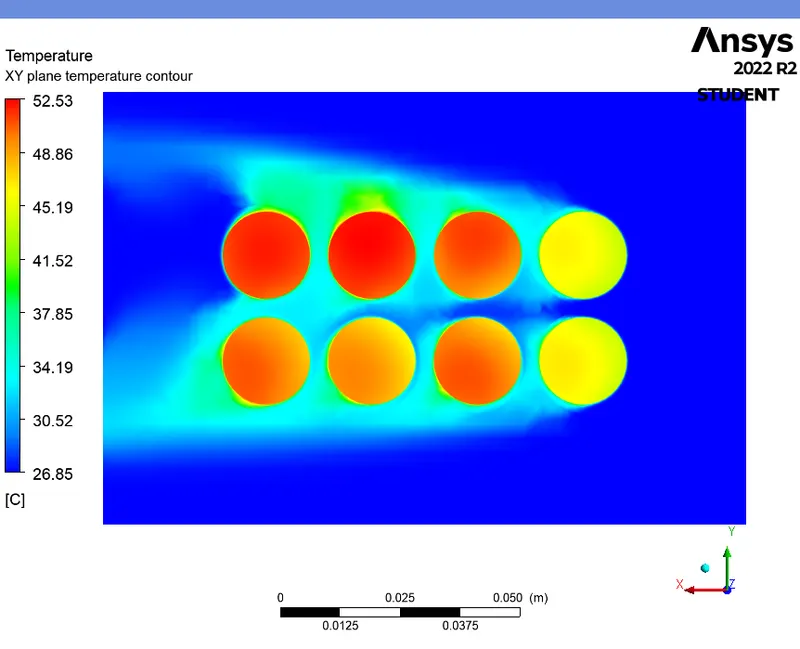
TEMPERATURE CONTOUR (XY plane) :
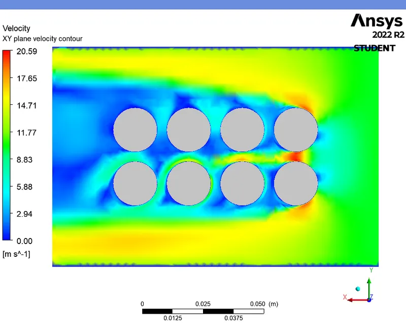
VELOCITY CONTOUR (XY plane) :
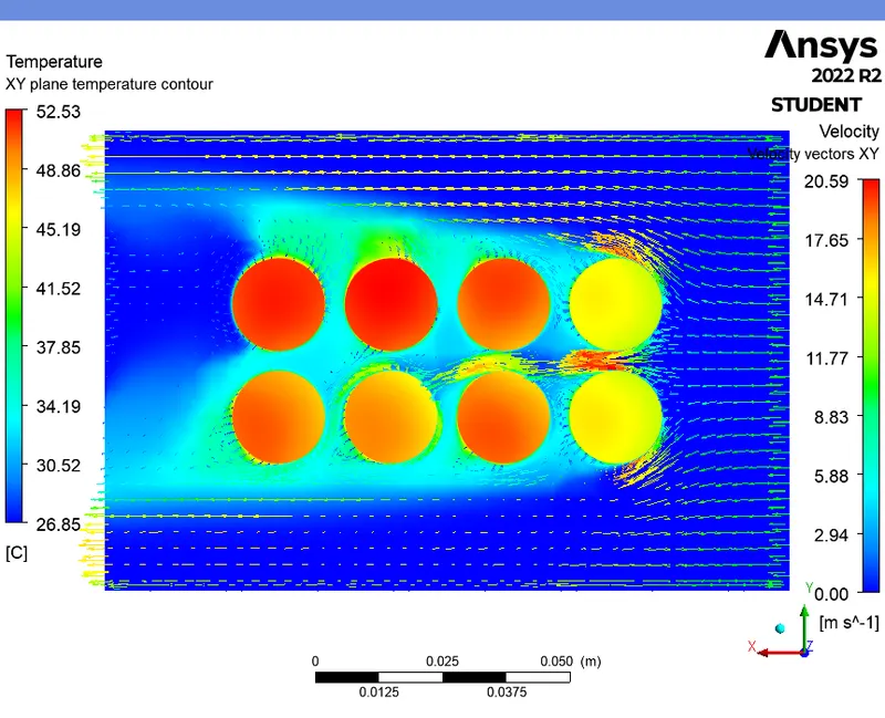
TEMPERATURE CONTOUR WITH VELOCITY VECTORS (XY plane) :
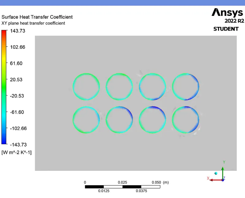
HEAT TRANSFER COEFFICIENT CONTOUR (XY plane) :
TEMPERATURE CONTOUR (XZ plane) :
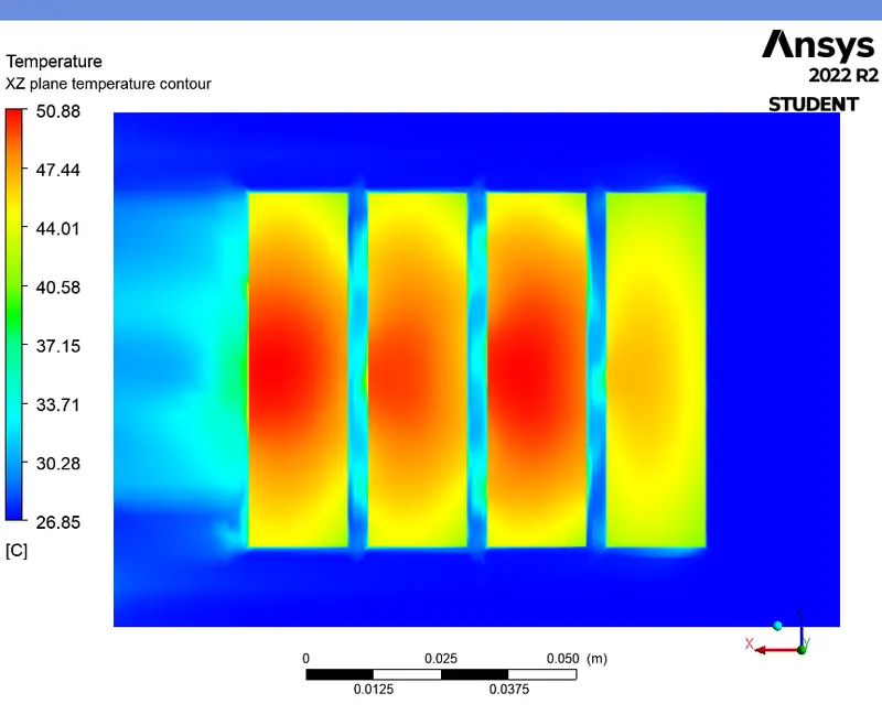
VELOCITY CONTOUR (XZ plane) :
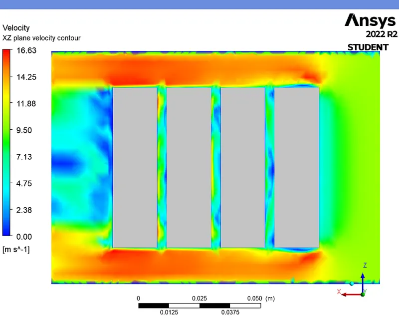
TEMPERATURE CONTOUR WITH VELOCITY VECTORS (XZ plane) :
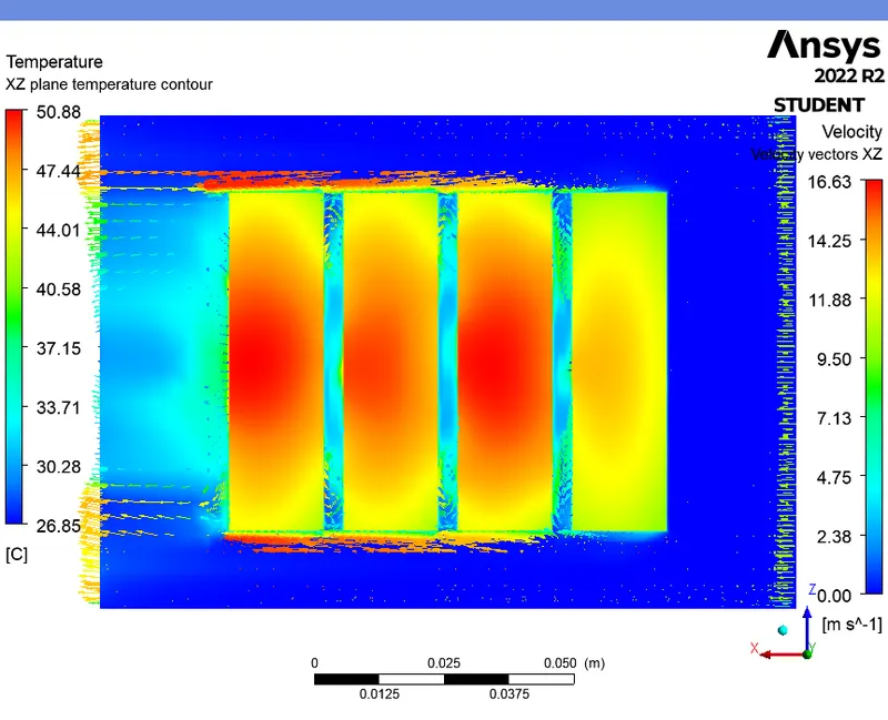
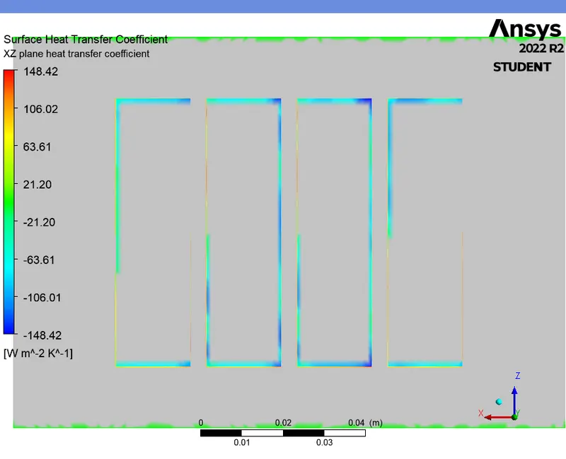
HEAT TRANSFER COEFFICIENT CONTOUR (XZ plane) :
CASE 7 (For 6mm gap and 10m/s - Steady state) :
PRE-PROCESSING :
- In this case, for the same velocity of 10m/s, we change the space between the batteries to 6mm.
- Repeat the same procedure as discussed in the previous case.
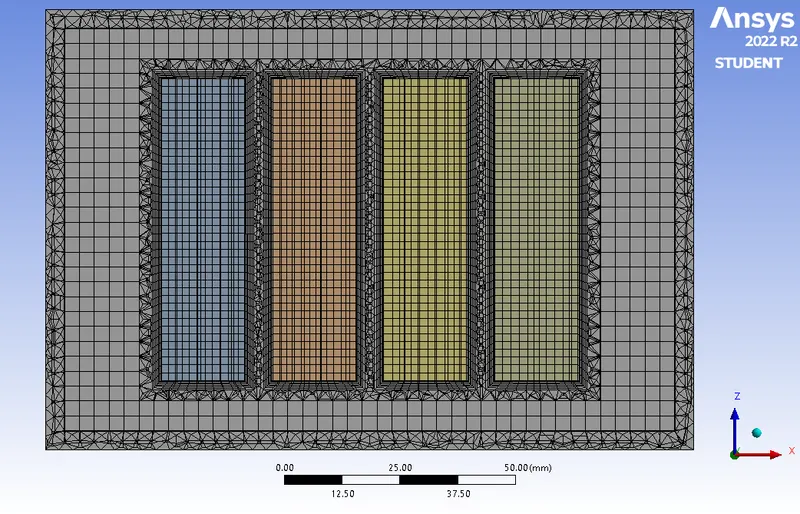
- Cross sectional view
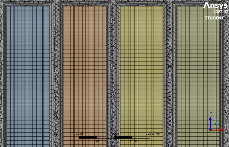
- Inflation view
|
Cells |
Faces |
Nodes |
|
448864 |
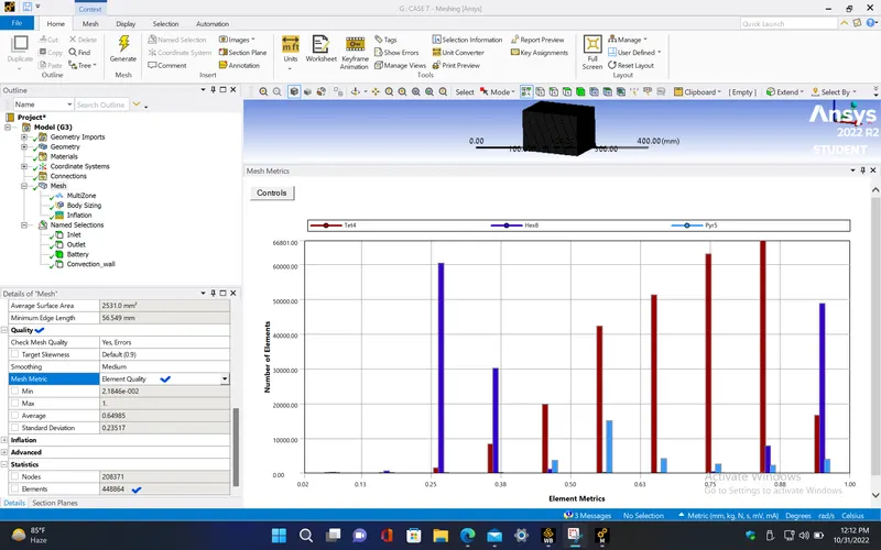
1079464 |
221571 |
|
Name |
Type |
Min Orthogonal Quality |
Max Aspect Ratio |
|
volume-volume_enclosure |
Mixed Cell |
0.099460827 |
126.6828 |
|
battery |
Hex Cell |
0.87981165 |
2.7495816 |
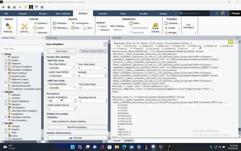
SETUP AND SOLVING :
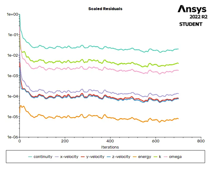
RESIDUALS PLOT :
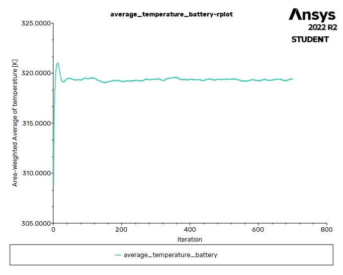
AVERAGE TEMPERATURE PLOT (Battery) :
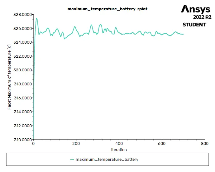
MAXIMUM TEMPERATURE PLOT (Battery) :
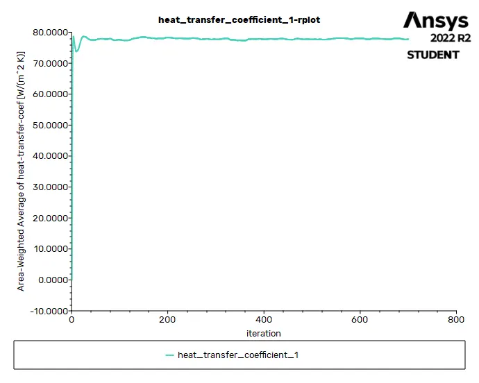
HEAT TRANSFER COEFFICIENT PLOT (over Battery) :
Solution status :
- From the above plots, we see that the solution got converged at 650th iteration since the rate at which residuals, average temperature, maximum temperature and heat transfer coefficient changes become constant over iteration.
|
Value |
Absolute Criteria |
Convergence Status |
|
|
continuity |
0.02003711 |
0.001 |
Not Converged |
|
x-velocity |
0.0001339254 |
0.001 |
Converged |
|
y-velocity |
7.994396e-05 |
0.001 |
Converged |
|
z-velocity |
7.442647e-05 |
0.001 |
Converged |
|
energy |
7.978816e-06 |
1e-06 |
Not Converged |
|
k |
0.00395816 |
0.001 |
Not Converged |
|
omega |
0.00180335 |
0.001 |
Not Converged |
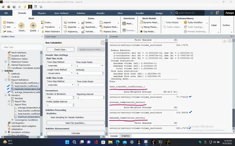
Report definitions :
|
heat_transfer_coefficient_1 |
77.77603 |
W/(m^2 K) |
|
maximum_temperature_battery |
325.1728 |
K |
|
average_temperature_battery |
319.3932 |
K |
POST PROCESSING :
TEMPERATURE CONTOUR (Battery) :
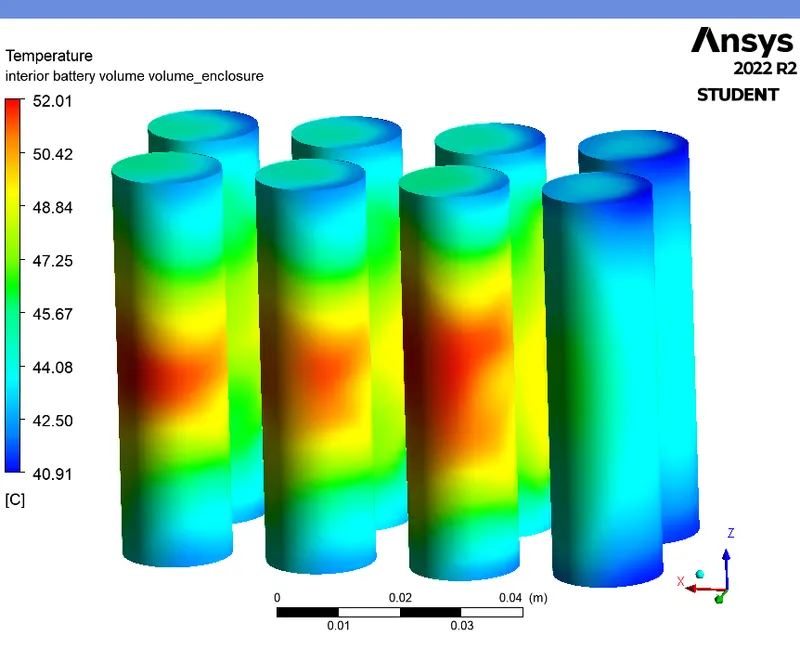
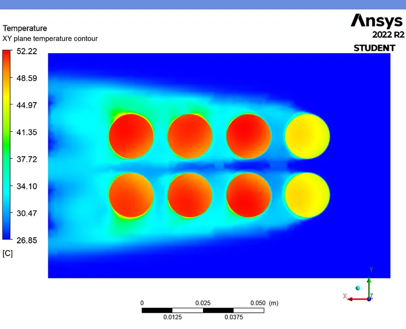
TEMPERATURE CONTOUR (XY plane) :
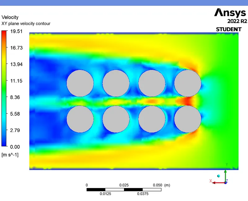
VELOCITY CONTOUR (XY plane) :
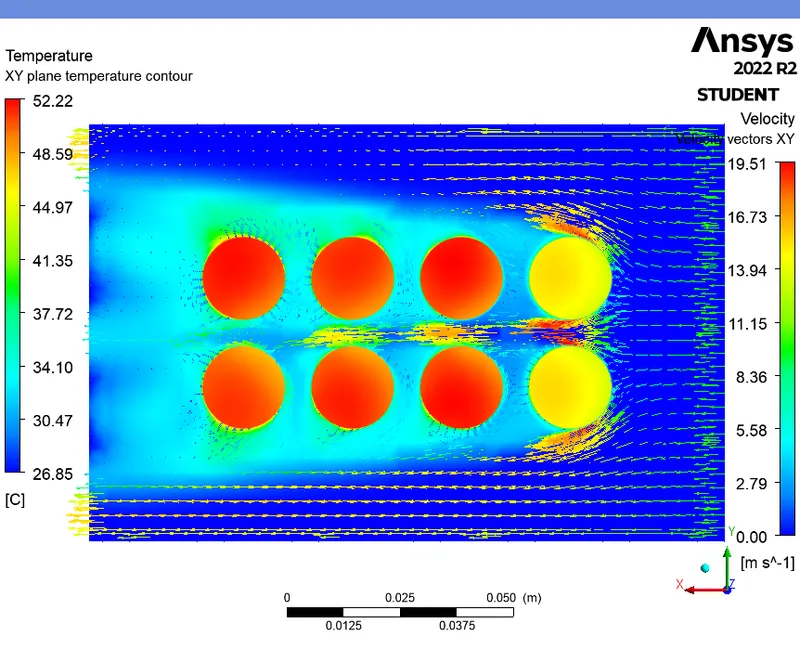
TEMPERATURE CONTOUR WITH VELOCITY VECTORS (XY plane) :
HEAT TRANSFER COEFFICIENT CONTOUR (XY plane) :
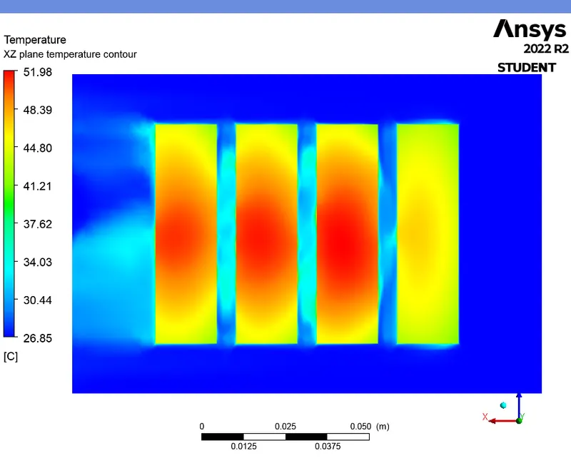
TEMPERATURE CONTOUR (XZ plane) :
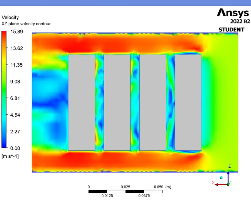
VELOCITY CONTOUR (XZ plane) :
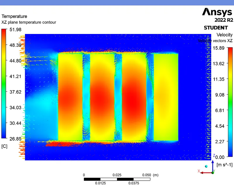
TEMPERATURE CONTOUR WITH VELOCITY VECTORS (XZ plane) :
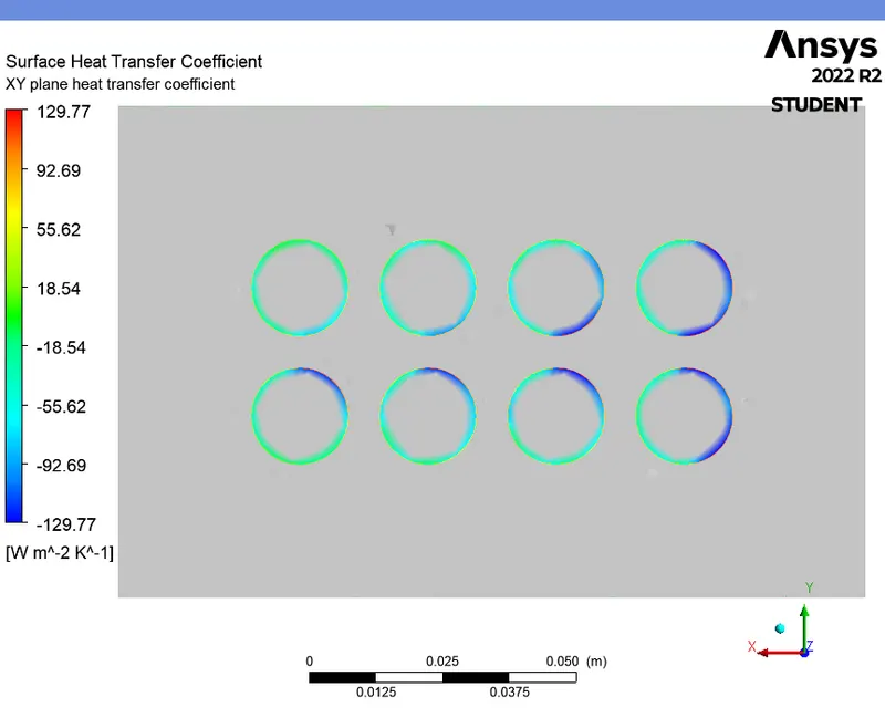
HEAT TRANSFER COEFFICIENT CONTOUR (XZ plane) :
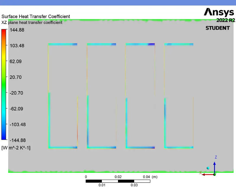
CASE 8 (For 4mm gap and 10m/s - Transient state) :
- In this simulation, we use transient state for the solver time for the inlet velocity of air taken as 10m/s and the space between the batteries as 4mm as same in Case-6.
|
Cells |
Faces |
Nodes |
|
406136 |
988212 |
210471 |
SETUP AND SOLVING :
|
Model |
Settings |
|
Space |
3D |
|
Time |
Unsteady, 1st-Order Implicit |
|
Viscous |
SST k-omega turbulence model |
|
Heat Transfer |
Enabled |
Boundary conditions :
|
inlet |
|
|
Velocity Specification Method |
Magnitude, Normal to Boundary |
|
Reference Frame |
Absolute |
|
Velocity Magnitude [m/s] |
10 |
|
Supersonic/Initial Gauge Pressure [Pa] |
0 |
|
Temperature [K] |
300 |
|
outlet |
|
|
Backflow Reference Frame |
Absolute |
|
Gauge Pressure [Pa] |
0 |
|
Backflow Total Temperature [K] |
300 |
|
Backflow Direction Specification Method |
Normal to Boundary |
|
Wall |
|
|
interior-battery-volume-volume_enclosure-shadow |
|
|
Material Name |
lithium |
|
Thermal BC Type |
Coupled |
|
Wall Motion |
Stationary Wall |
|
Shear Boundary Condition |
No Slip |
|
interior-battery-volume-volume_enclosure |
|
|
Material Name |
lithium |
|
Thermal BC Type |
Coupled |
|
convection_wall |
|
|
Material Name |
aluminum |
|
Thermal BC Type |
Convection |
|
Convective Heat Transfer Coefficient [W/(m^2 K)] |
5 |
|
Free Stream Temperature [K] |
300 |
|
Wall Motion |
Stationary Wall |
|
Shear Boundary Condition |
No Slip |
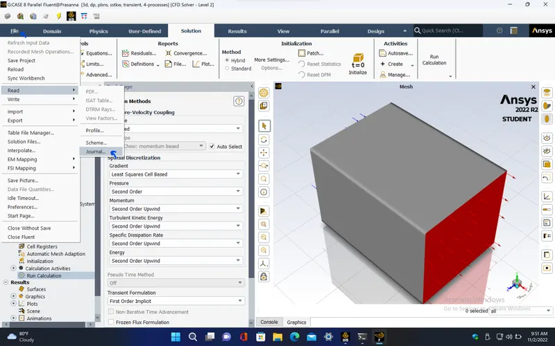
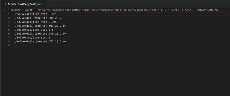
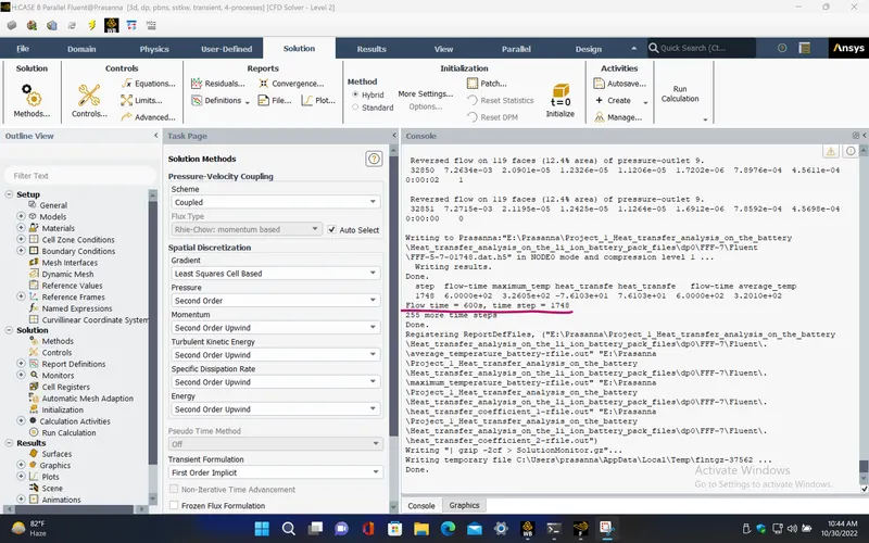
- Here, we run the simulation for 600 flow seconds.
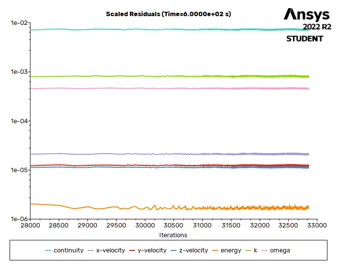
RESIDUALS PLOT :
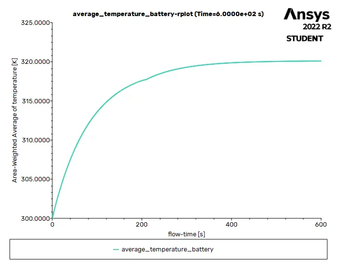
AVERAGE TEMPERATURE PLOT (Battery) :
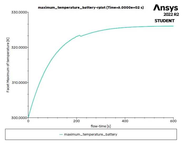
MAXIMUM TEMPERATURE PLOT (Battery) :
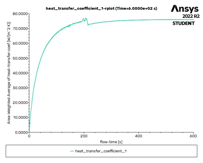
HEAT TRANSFER COEFFICIENT PLOT (over Battery) :
Solution status :
- From the above plots, we see that the solution got converged at 500th flow second since the rate at which residuals, average temperature, maximum temperature and heat transfer coefficient changes become constant over time.
|
Value |
Absolute Criteria |
Convergence Status |
|
|
continuity |
0.007271469 |
0.001 |
Not Converged |
|
x-velocity |
2.119472e-05 |
0.001 |
Converged |
|
y-velocity |
1.242484e-05 |
0.001 |
Converged |
|
z-velocity |
1.126376e-05 |
0.001 |
Converged |
|
energy |
1.69123e-06 |
1e-06 |
Not Converged |
|
k |
0.0007859206 |
0.001 |
Converged |
|
omega |
0.0004569833 |
0.001 |
Converged |
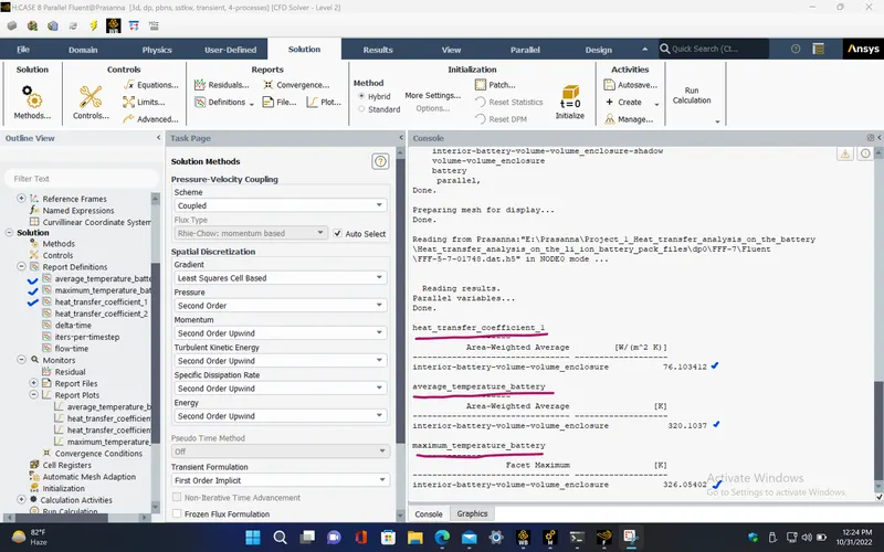
Report definitions :
|
average_temperature_battery |
320.1037 |
K |
|
maximum_temperature_battery |
326.054 |
K |
|
heat_transfer_coefficient_1 |
76.10341 |
W/(m^2 K) |
|
flow-time |
600 |
s |
PRE-PROCESSING :
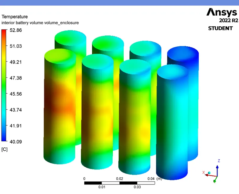
TEMPERATURE CONTOUR (Battery) :
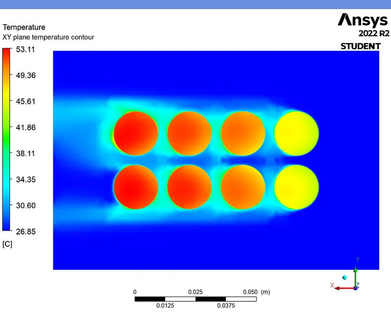
TEMPERATURE CONTOUR (XY plane) :
VELOCITY CONTOUR (XY plane) :
TEMPERATURE CONTOUR WITH VELOCITY VECTORS (XY plane) :
HEAT TRANSFER COEFFICIENT CONTOUR (XY plane) :
TEMPERATURE CONTOUR (XZ plane) :
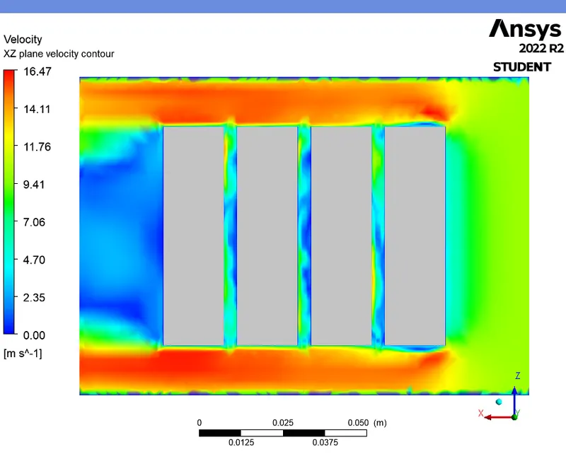
VELOCITY CONTOUR (XZ plane) :
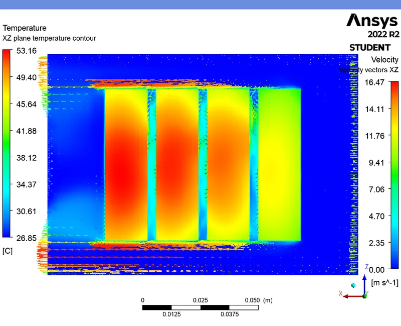
TEMPERATURE CONTOUR WITH VELOCITY VECTORS (XZ plane) :
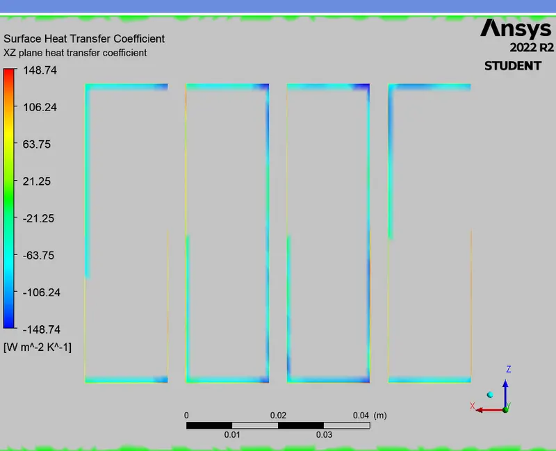
HEAT TRANSFER COEFFICIENT CONTOUR (XZ plane) :
RESULTS :
|
NUMBER OF MESH ELEMENTS |
SOLVER TIME |
INLET VELOCITY OF AIR ('m/s') |
GAP BETWEEN BATTERIES ('mm') |
AVERAGE TEMPERATURE OF THE BATTERY ('K') |
MAXIMUM TEMPERATURE OF THE BATTERY ('K') |
HEAT TRANSFER COEFFICIENT OVER THE BATTERY ('W/m^2-K') |
|
|
CASE 3 |
415507 |
Steady state |
3 |
2 |
360.7065 |
393.9565 |
35.58587 |
|
CASE 4 |
415507 |
Steady state |
5 |
2 |
340.9346 |
365.388 |
48.64977 |
|
CASE 5 |
415507 |
Steady state |
10 |
2 |
321.3586 |
333.1902 |
74.36751 |
|
CASE 6 |
406136 |
Steady state |
10 |
4 |
318.9057 |
325.3957 |
78.9569 |
|
CASE 7 |
448864 |
Steady state |
10 |
6 |
319.3932 |
325.1728 |
77.77603 |
|
CASE 8 |
406136 |
Transient state |
10 |
4 |
320.1037 |
326.054 |
76.10341 |
Animation videos google drive link:
1. https://drive.google.com/file/d/1AlY8FTLevPTwcZAksFjM8_EofLPLZjUG/view?usp=share_link
2. https://drive.google.com/file/d/1fRw7_sCvVz71RN741PGhbBP0Ec44b74G/view?usp=share_link
CONCLUSION :
- From the above table, we can see that, as the inlet velocity of air increases, the temperature of the battery decreases since the heat transfer coefficient over the battery is increased. Also foer the same inlet velocity of 10 m/s, as the gap is increased between the batteries, the temperature decreases but the temperature difference between the Case-6 of 4mm gap and Case-7 of 6mm gap is almost same. So, we can conclude that the Case-6 with 4mm gap and 10 m/s velocity is considered as the effective cooling criteria for this 4x2 battery pack.
TEMPERATURE CONTOUR WITH VELOCITY VECTORS (XY plane) :
HEAT TRANSFER COEFFICIENT CONTOUR (XY plane) :
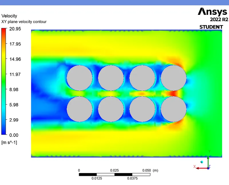
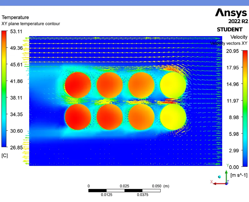
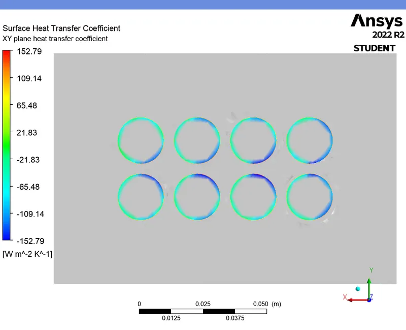
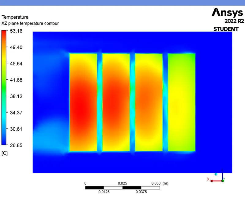
- From the above contour plots of Case 4, we can see that, the temperature of the battery facing the inlet have less temperature compared to others since the heat transfer coefficient is higher over those regions.
- The temperature of the battery near the outlet of the battery pack has the higher temperature compared to others since the air flow near to that surface is less which results in less convective heat transfer over that region.
REFERENCE :
1. https://cfdflowengineering.com/battery-cooling-techniques-in-electric-vehicle/