Week 10 - Simulating Combustion of Natural Gas.
Aim:-
Perform the heat transfer analysis using ANSYS-Fluent software for the cylindrical
Lithium ion Battery with heat generation boundary condition. Create an enclosure and
use air as the working fluid for cooling the battery back system (4 x 2). Take air inlet
temperature as 300 K and gap between the batteries as 2 mm.
Property of the Lithium-ion Battery
Density = 2700 kg/m3
Specific heat = 900 J/kg.K
Thermal Conductivity = 7.14 W/m.K
Heat Generation per battery = 10 W
Size of the Battery = 18 mm diameter and 65 mm height.
Expected results:
• Explain why battery cooling is needed. And give a brief description about various
techniques for battery cooling.
• Perform Mesh independent study for any one case and based on your judgment
use the more suitable model for further cases.
• Run the simulation by varying the velocity of air as 3, 5 and 10m/sec and discuss
the results.
• Find out the maximum temperature and heat transfer coefficient obtained by the
battery.
• Based on the results and on your judgment, select one case (3, 5 or 10 m/s) and
vary the space between the batteries as 2, 4 and 6 mm, then discuss the results.
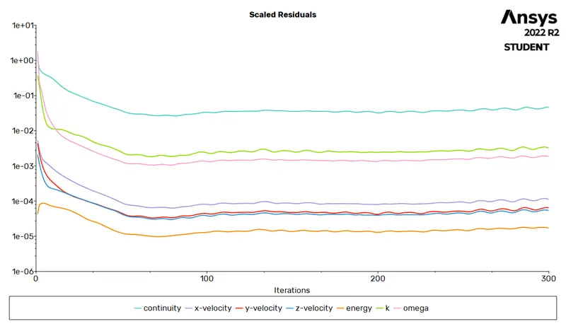
• Prove that the simulation has achieved convergence with appropriate images and
plots (Velocity and temperature contour plots on the cut planes).
• Create the animation to observe the temperature distribution and velocity vector.
• Summarize the results in tabulation/ graphical form.
• Identify potential hotspots on the model.
• State the inferences based on the result
Objective:- Simulation for 4*2 battery arrangment.
Theroy:-
BTMS:- BTMS sends for battery thermal management system.
The rise of renewable power generation in the current energy market has created an immense potential for different forms of energy storage. At the forefront of these storage technologies are the lithium batteries as they are lightweight with high energy density. The characteristics of Lithium batteries have made them attractive both for stationary and automotive applications. However, despite their promising future, there are major hindrances with regards to a battery system e.g. safety concerns, cost, limited calendar life, and temperature related issues. Temperature has a large effect on the safety, lifetime and performance of Li-ion batteries. The optimum operating range for these batteries is 15-35⁰C [1] otherwise the performance and lifespan will be reduced and furthermore hazardous incidents such as thermal runaway might occur. In addition, temperature difference among cells and modules in a battery pack must be controlled, else it will impact the operation and aging of the battery. Thus, an effective battery thermal management system is necessary to dissipate the heat generated inside the batteries.Moreover, in low-temperature scenarios, heating is required to ensure the best performance.
Li-ion batteries
Li-ion batteries consist of lithium in the positive electrode and electrolyte where lithium ions move from positive to negative electrode during charging and vice versa during discharge. What gives leverage to lithium-ion batteries compared to other battery technologies is their volumetric and mass energy density. This feature makes lithium-ion batteries very attractive for different applications, especially the automotive industry where the energy density is critical. Lithium Batteries are manufactured in three different form factors namely cylindrical, prismaticand pouch. In cylindrical cells, the layers are rolled and put into a cylindrical can Figure 1. The advantage of this cell format is mechanical stability and ease of manufacturing. Prismatic cell Figure 12 is wrapped in packages for thinner design demands. They are mainly found in electronic devices such as mobile phones. Pouch cells have the most efficient packaging by eliminating the metal enclosure and allow stacking.
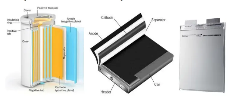
BTMS:- the inappropriate battery temperature will have a negative impact on the performance, lifetime and safety of the batteries. Therefore, a BTMS is required for every battery system. The primary duty of a BTMS is to keep the batteries in the optimum temperature range and maintain an even temperature distribution in the battery pack. Afterward, other factors such as weight, size, reliability and the cost must be taken into consideration based on the application of the battery packs
1. air cooling
Air is the most conventional way for cooling and has been used widely in various industries. Due to low heat capacity and low thermal conductivity, air might not seem to be a good cooling
2. liquid cooling
Liquid coolants have several advantages compared to air. Liquid cooling is more compact thanair without sacrificing any cooling capacity. Liquid coolants can be 3500 times more efficient
2.1 Direct Liquid cooling
2.2 Indirect liquid cooling
3. phase change material(pcm)
in this type of cooling we uses wax o any phase changing material to observe heat from the battery and to relaease this heat to the surroundings.
CFD:-Computational fluid dynamics or CFD is the analysis of systems involving fluid flow, heat transfer and associated phenomena such as chemical reactions by means of computer-based simulation.
Practical application in current scenario
- aerodynamics of aircraft and vehicles: lift and drag
• hydrodynamics of ships
• power plant: combustion in internal combustion engines and gas
turbines
• turbomachinery: flows inside rotating passages, diffusers etc.
• electrical and electronic engineering: cooling of equipment including
microcircuits
• chemical process engineering: mixing and separation, polymer moulding
• external and internal environment of buildings: wind loading and
heating/ventilation
• marine engineering: loads on off-shore structures
• environmental engineering: distribution of pollutants and effluents
• hydrology and oceanography: flows in rivers, estuaries, oceans
• meteorology: weather prediction
• biomedical engineering: blood flows through arteries and veins
CFD Work Flow:- CFD codes are structured around the numerical algorithms that can tackle fluid flow problems. In order to provide easy access to their solving power all commercial CFD packages include sophisticated user interfaces to input problem parameters and to examine the results
Its threee step process
(i) a pre-processor
involves defination of geometry, grid generation, selection of phenomenon that need to model
(ii) a solver
intergration of governing equation, discretisation and solution
(iii) a post-processor
ploting of contour, graphs and making movies.
In solving fluid flow problems we need to be aware that the underlyingphysics is complex and the results generated by a CFD code are at best asgood as the physics (and chemistry) embedded in it and at worst as good asits operator with CFD
Solving and Modeling Approch:-
There are no way present to understand and analyse the effeciveness of the mixiing tee model.
1. analytical approch
2. simulation approch
3. experimental approch
using analytical approch and experimental approch is time consuming and high cost senario. this could be eliminated by using simulation approch in which we can analyse the system with the actual codition we are intrested in.
To do this we are using ansys fluent solver
we are using fluid flow analysis using Fluent solver because we are interested in the total effectiveness of the fluid in the mechnical tee model, here we are using two different models to analyse the effectiveness of the mixing of fluid.
Approch we are using.
1. We need to open Ansys workbench
2. Choose the Appropiate Solver
3. Assign Appropiate name
4. Choose geometry and select new spaceclaim model.
5. Load the appropiate file
6. Implement the geometrical operation
7. Apply the mesh and provide name selection
8. Choose setup, select the appropiate model
9. Initalisation and running the simulation
10. Result making i.e. countour plots graphs
1. Opening Ansys workbench
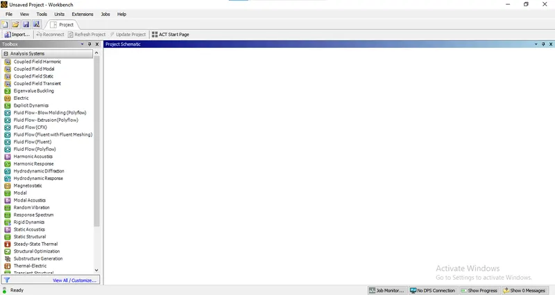
2. Choose the Appropiate Solver
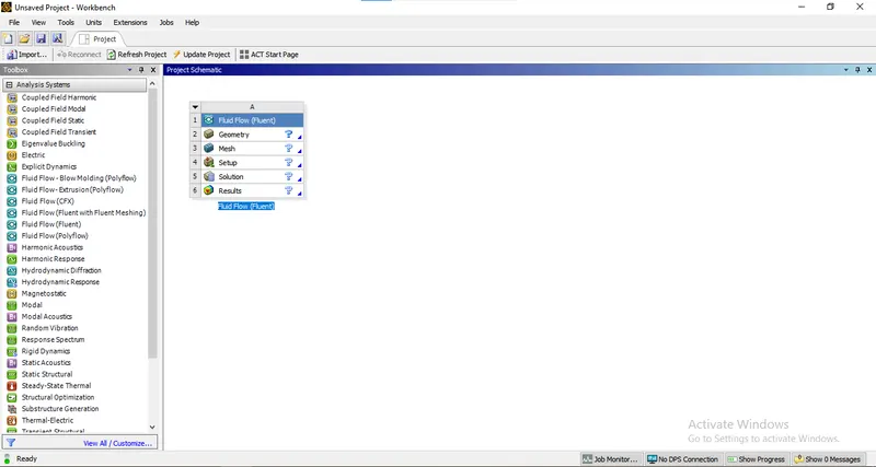
3. Assign Appropiate name:- battery
4. Opening of space claim geometry do to geometrical operation
1. Create a small circle of dia 18mm
2. use pattern option to create indenticial circles in the form of 4 *2 battery gap between battery are 2 4 6mm respectively
3. now use pull tool to extract the circle upto 65mm
4. now create a enclosure front 20mm back 20mm leftside 20mm rightside 20mm top and buttom 15mm
5. now use share topology
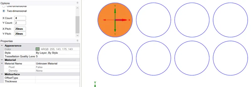
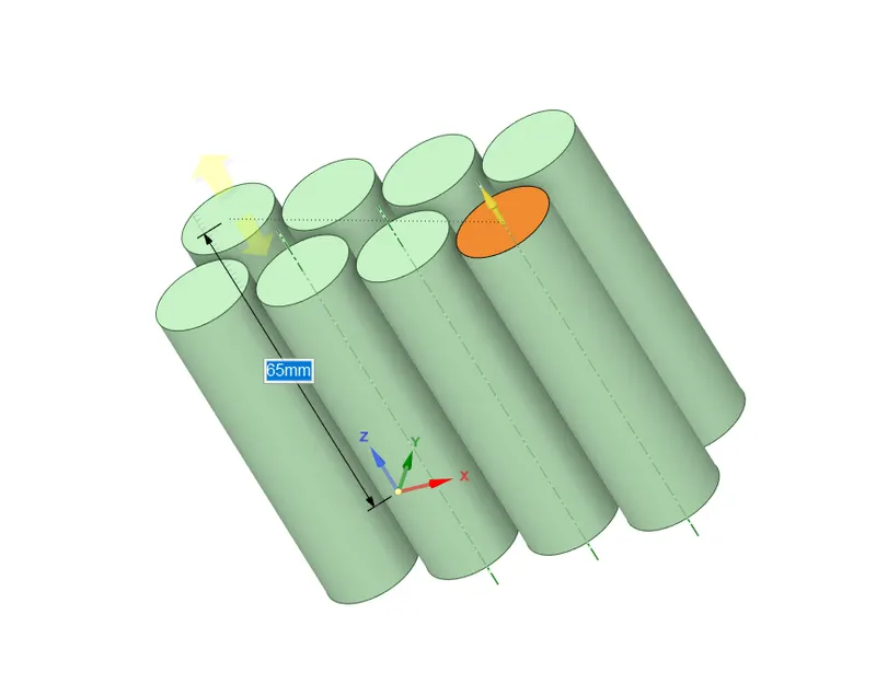
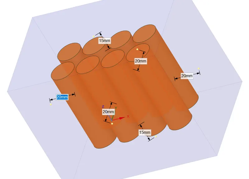
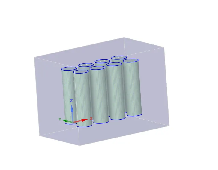
we done with geometric part we can move to meshing mode.
5. Meshing
1. choose default mesh length as 3 mm and 5mm respectively
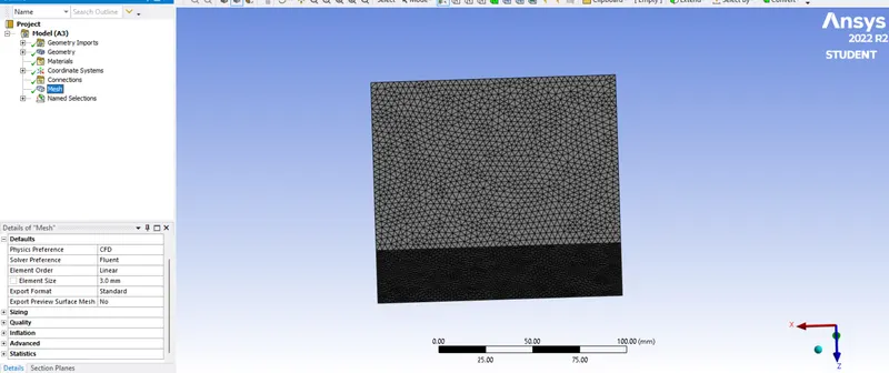
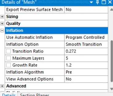
2. Now Create inflation layer
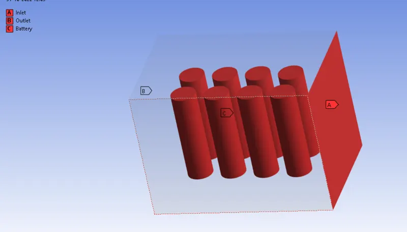
3. Now give name selection.
6. Setup:-
Settings
| Solver | Steady State |
| Energy Equation | On |
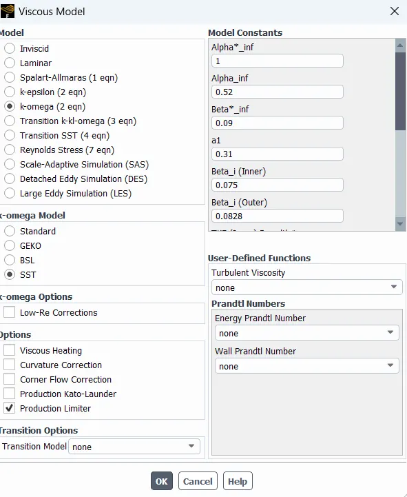
| Model | k-omega sst |
| Inlet | Inlet |
| Outlet | Pressure Outlet |
| Material_(Fluid) | Air, Alluminium lithium(user defined) |
| Cell Zone Condition | lithium, alluminium |
cases and inputs:-
| Sr No | Mesh Length in mm | Gap in mm | Velocity in m/s |
| 1 | 3 | 2 | 3 |
| 2 | 3 | 2 | 5 |
| 3 | 3 | 2 | 6 |
| 4 | 3 | 4 | 3 |
| 5 | 3 | 6 | 3 |
| 6 | 5 | 2 | 3 |
Results:-
# Keeping mesh length and gap constant and varrying the velocity.
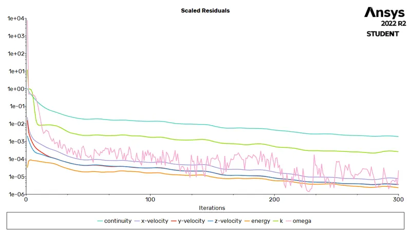
1. residuals
| Mesh length 3, gap 2 velocity 3 | Mesh length 3, gap 2 velocity 5 | Mesh length 3, gap 2 velocity 10 |
 |
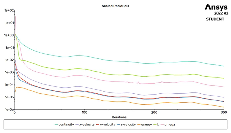 |
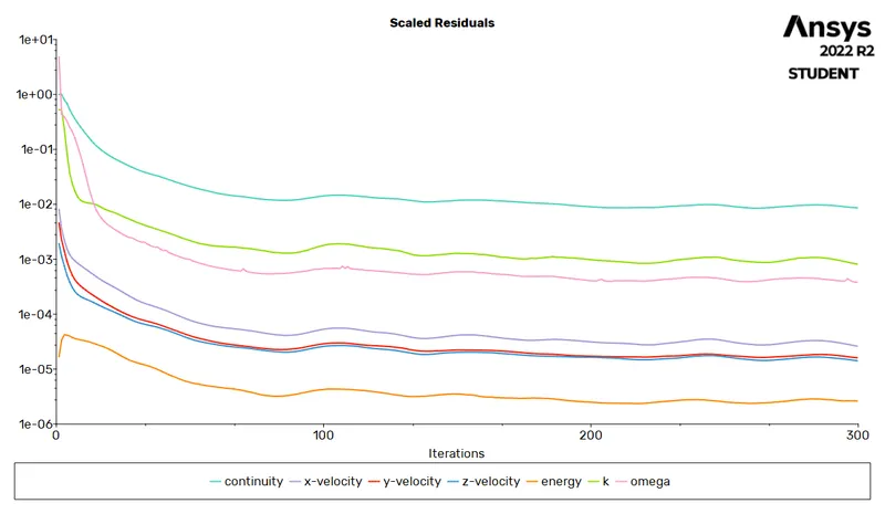 |
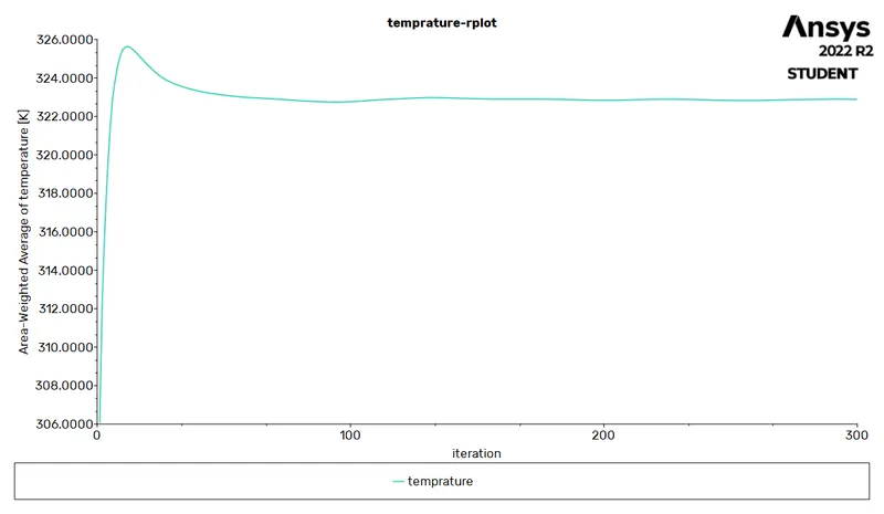
2. temprature
| Mesh length 3, gap 2 velocity 3 | Mesh length 3, gap 2 velocity 5 | Mesh length 3, gap 2 velocity 10 |
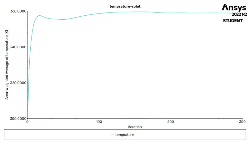 |
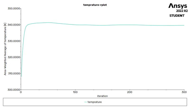 |
 |
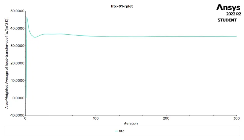
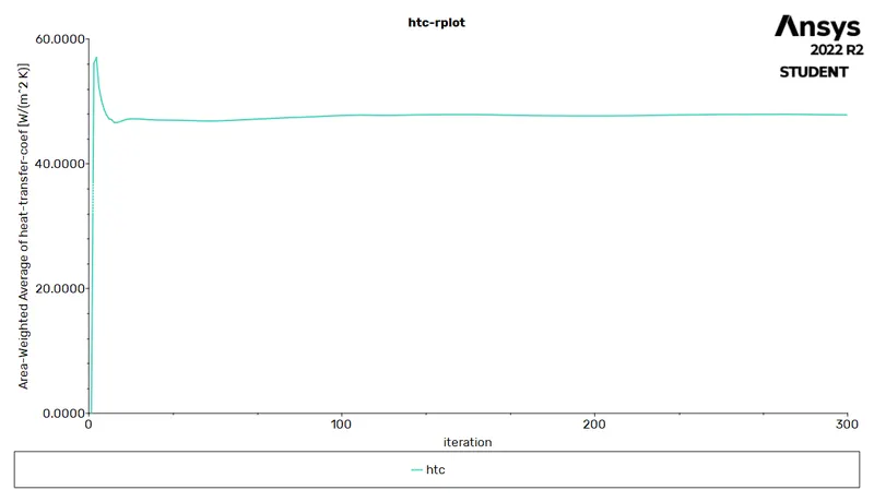
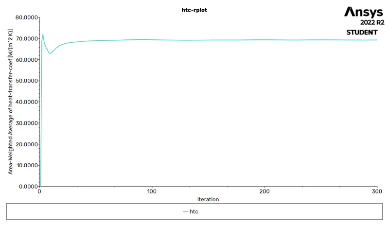
3. htc
| Mesh length 3, gap 2 velocity 3 | Mesh length 3, gap 2 velocity 5 | Mesh length 3, gap 2 velocity 10 |
 |
 |
 |
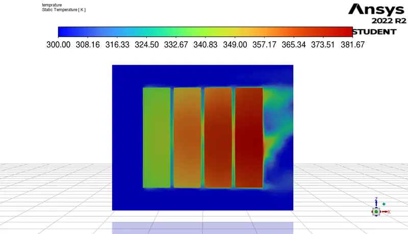
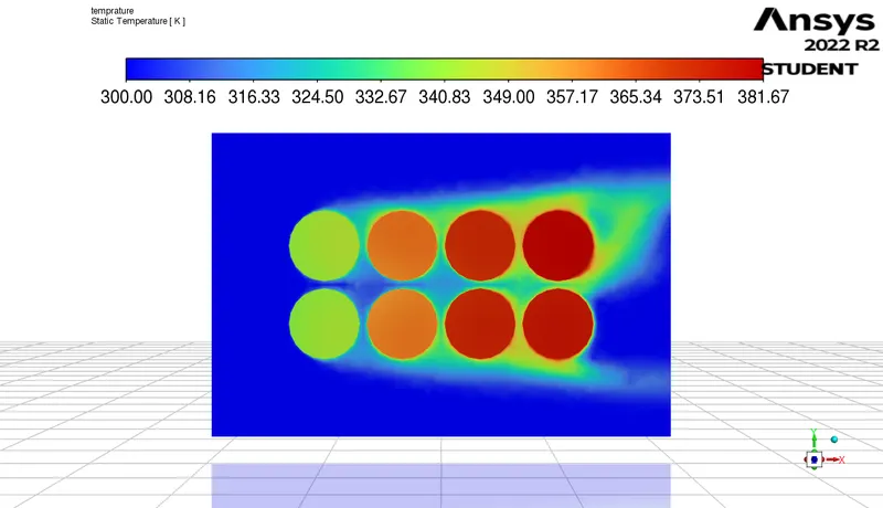
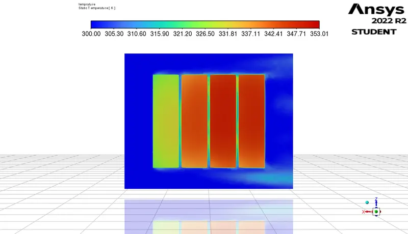
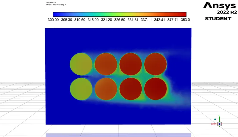
4. temprature contour
| Mesh length 3, gap 2 velocity 3 | Mesh length 3, gap 2 velocity 5 | Mesh length 3, gap 2 velocity 10 |
|
|
|
|
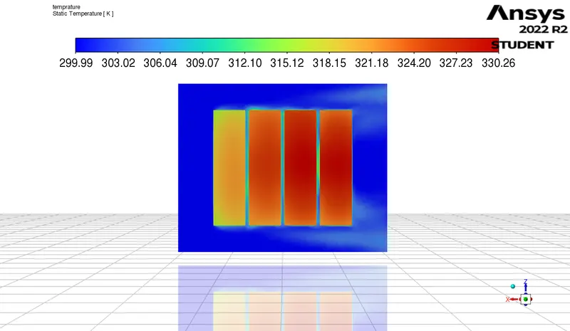
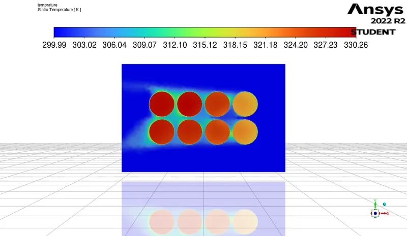
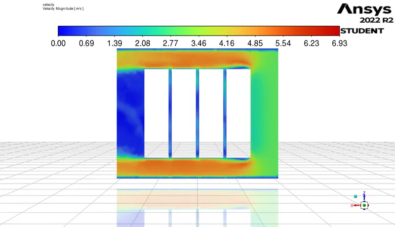
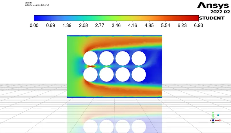
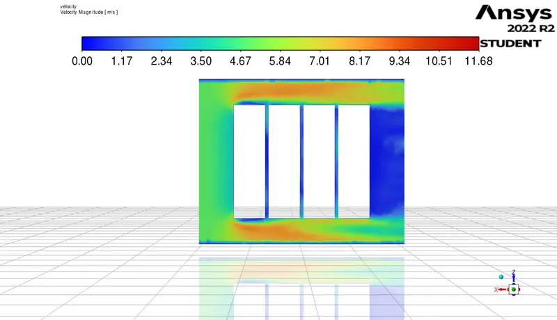
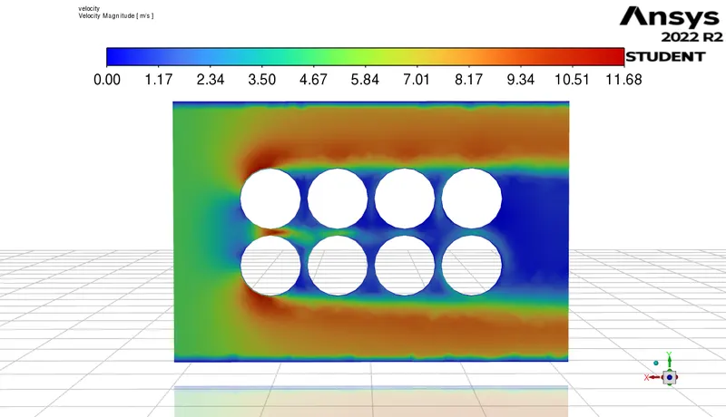
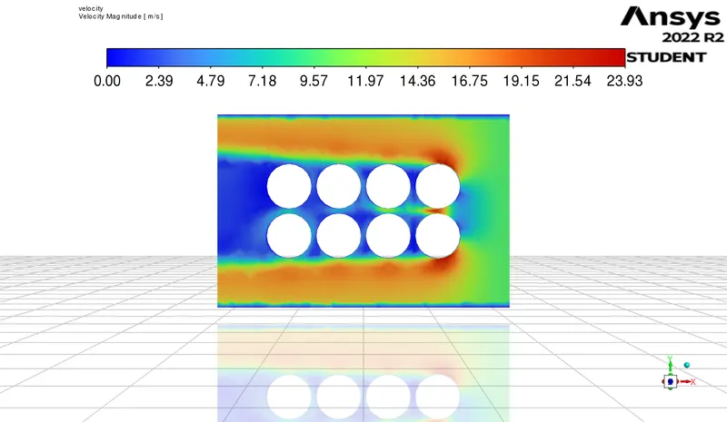
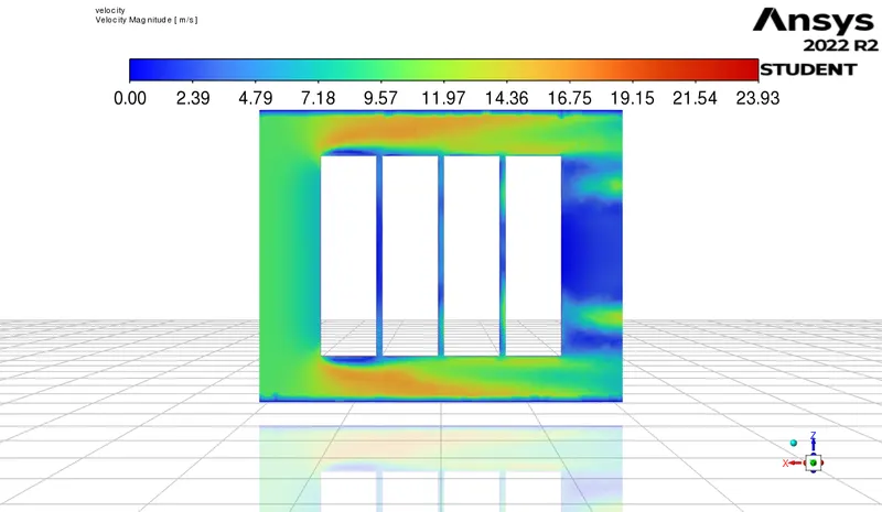
5. velocity contour
| Mesh length 3, gap 2 velocity 3 | Mesh length 3, gap 2 velocity 5 | Mesh length 3, gap 2 velocity 10 |
|
|
|
|
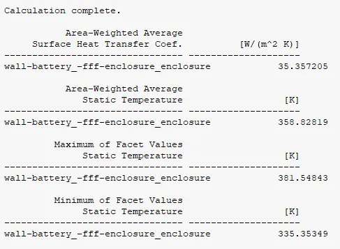
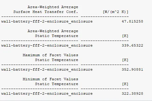
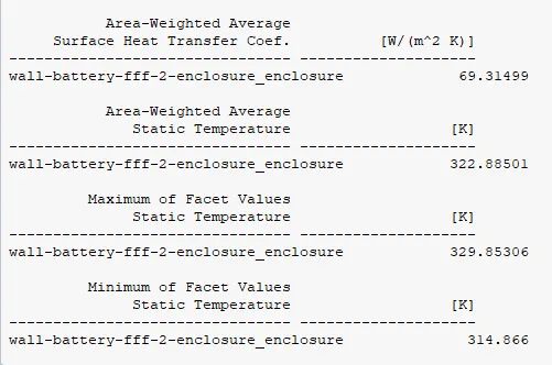
6. result ss
| Mesh length 3, gap 2 velocity 3 | Mesh length 3, gap 2 velocity 5 | Mesh length 3, gap 2 velocity 10 |
 |
 |
 |
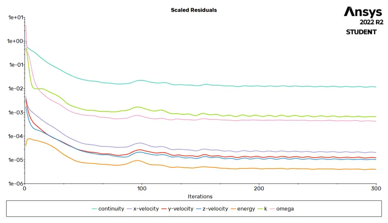
# Keeping velocity and mesh length constant and varrying the gap .
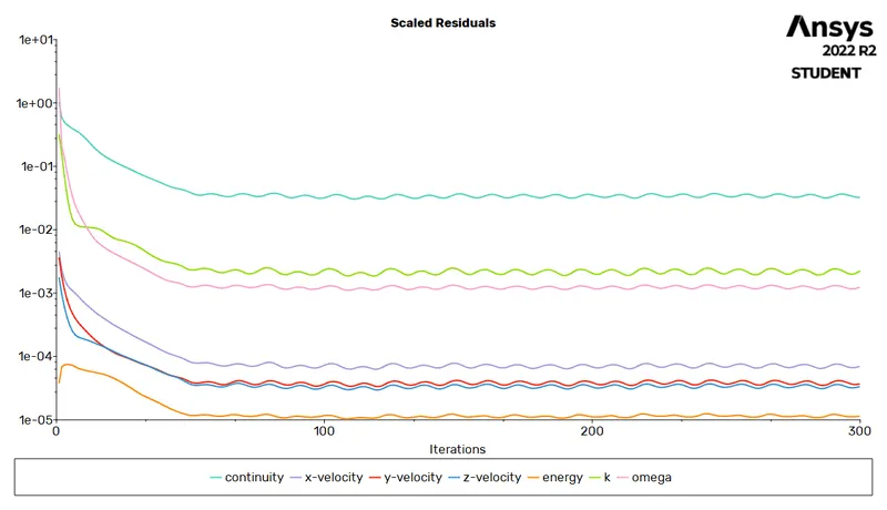
1. residual
| Mesh length 3, gap 2 velocity 3 | Mesh length 3, gap 4 velocity 3 | Mesh length 3, gap 6 velocity 3 |
|
 |
 |
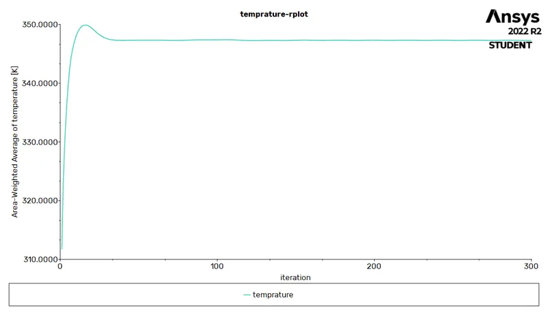
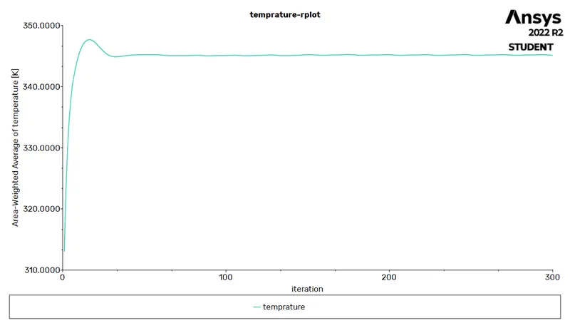
2. temprature
| Mesh length 3, gap 2 velocity 3 | Mesh length 3, gap 4 velocity 3 | Mesh length 3, gap 6 velocity 3 |
|
 |
 |
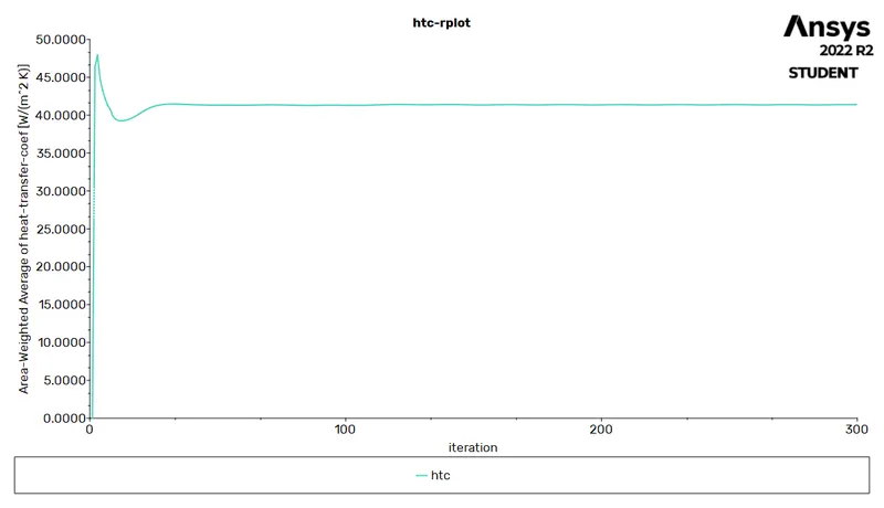
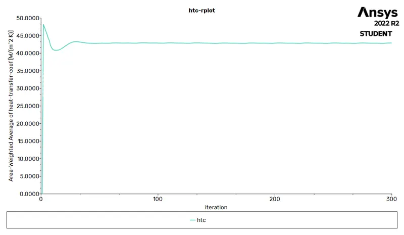
3. htc
| Mesh length 3, gap 2 velocity 3 | Mesh length 3, gap 4 velocity 3 | Mesh length 3, gap 6 velocity 3 |
|
 |
 |
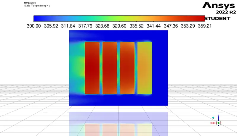
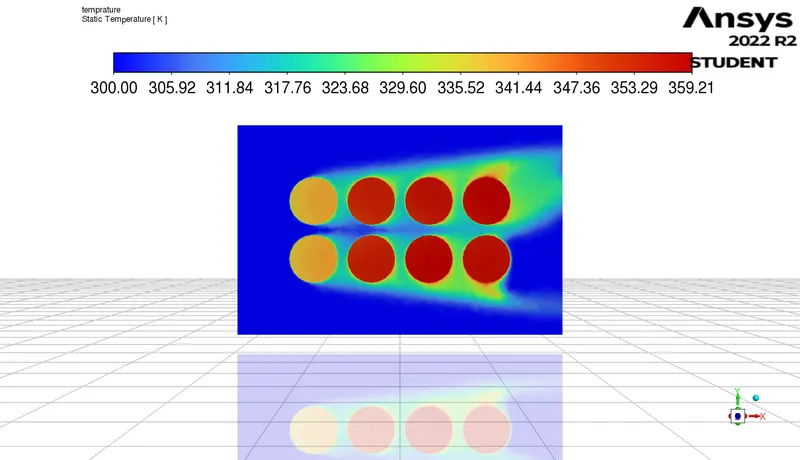
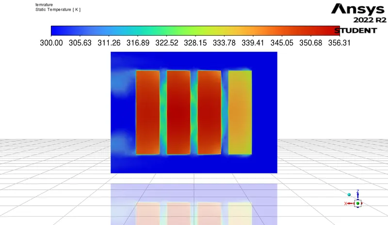
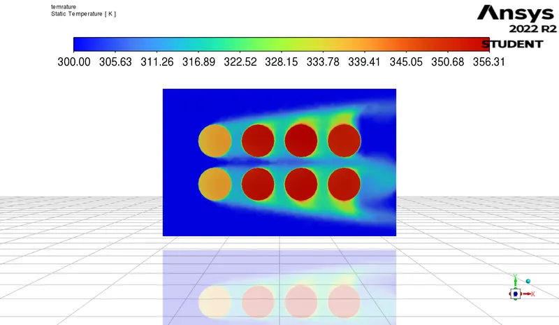
4. temprature contour
| Mesh length 3, gap 2 velocity 3 | Mesh length 3, gap 4 velocity 3 | Mesh length 3, gap 6 velocity 3 |
|
|
|
|
5. velocity contour
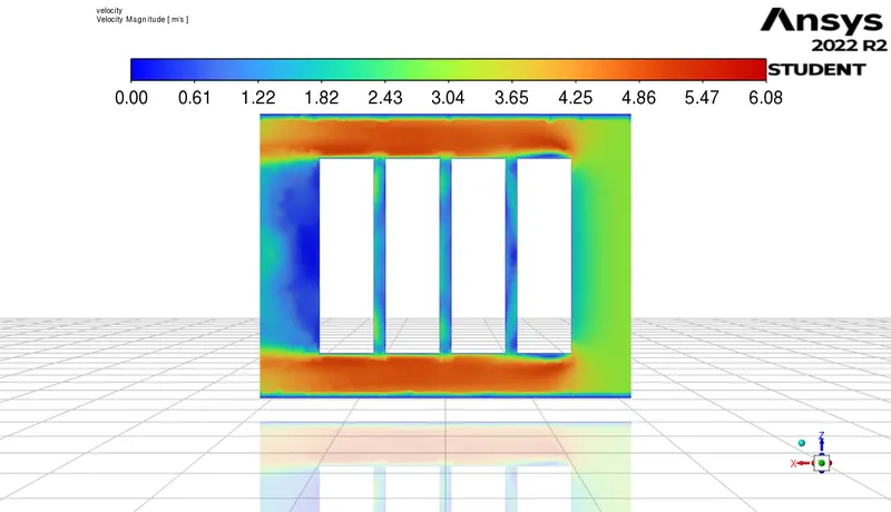
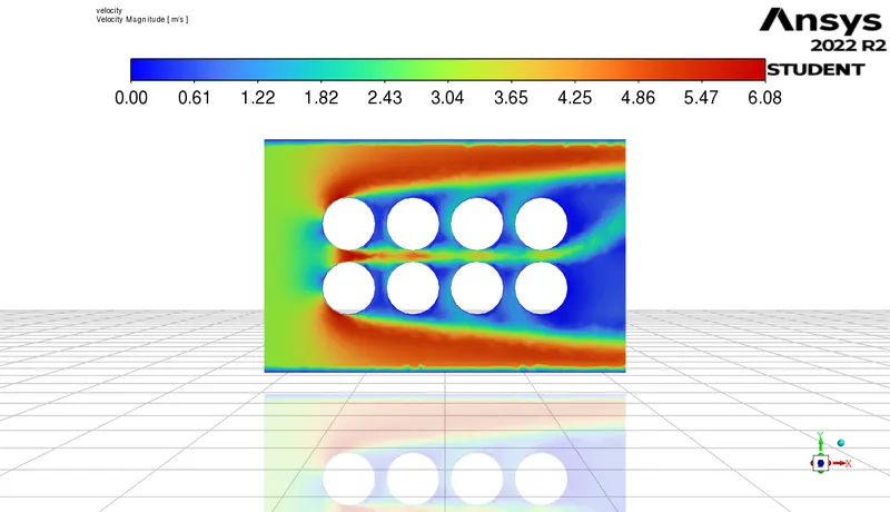
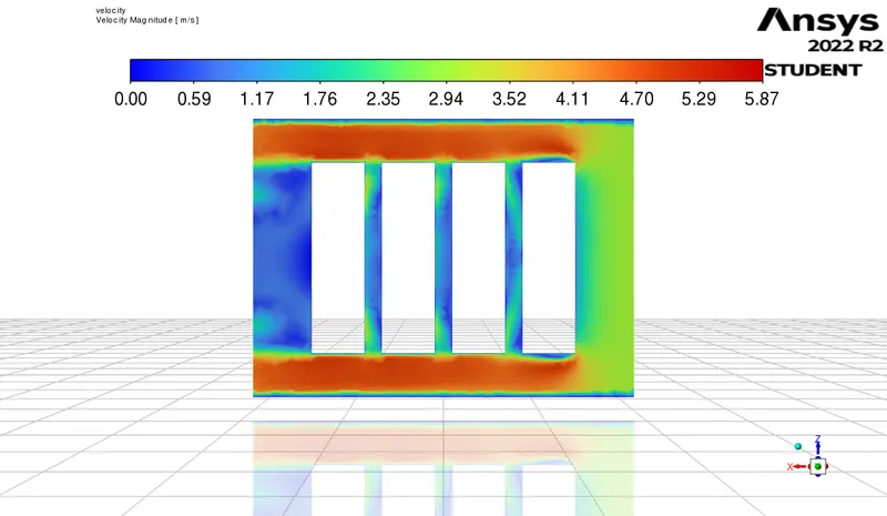
| Mesh length 3, gap 2 velocity 3 | Mesh length 3, gap 4 velocity 3 | Mesh length 3, gap 6 velocity 3 |
|
|
|
|
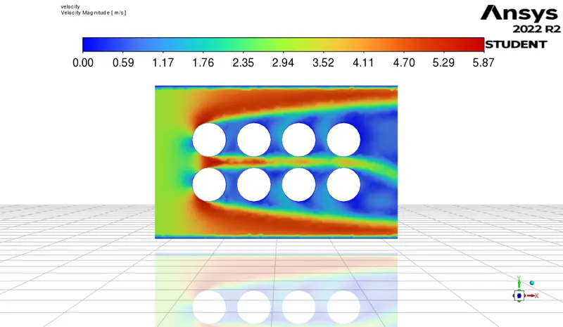
6. result ss
| Mesh length 3, gap 2 velocity 3 | Mesh length 3, gap 4 velocity 3 | Mesh length 3, gap 6 velocity 3 |
|
 |
 |
# mesh independent study
1. residual
| Mesh length 3, gap 6 velocity 3 | Mesh length 5, gap 6 velocity 3 |
|
 |
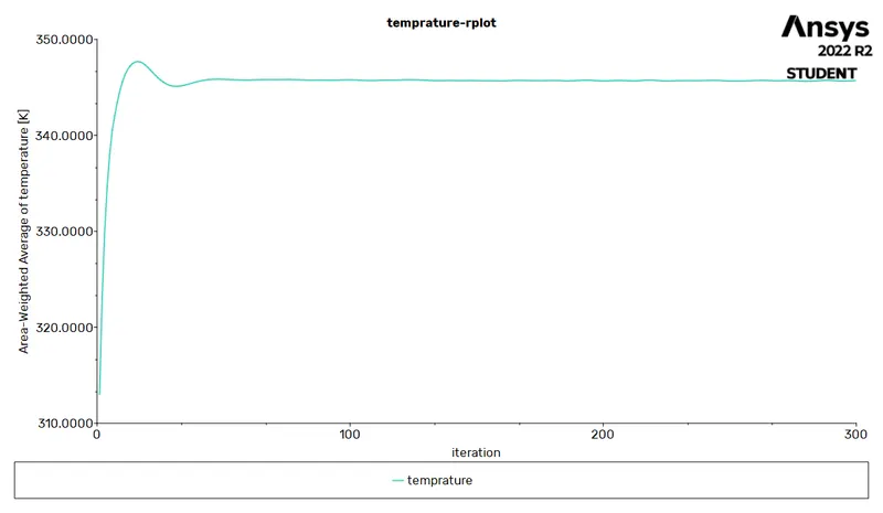
2. temprature
| Mesh length 3, gap 6 velocity 3 | Mesh length 5, gap 6 velocity 3 |
|
 |
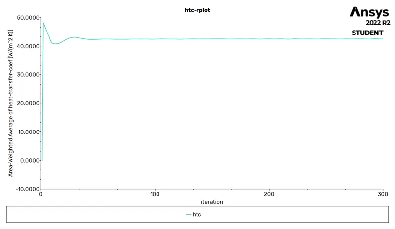
3. htc
| Mesh length 3, gap 6 velocity 3 | Mesh length 5, gap 6 velocity 3 |
|
 |
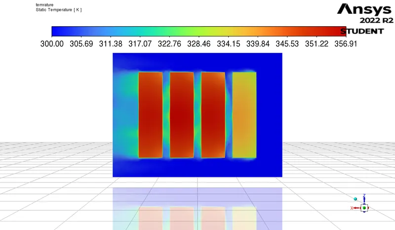
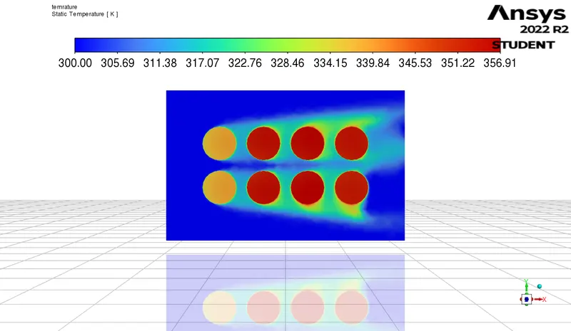
4. temprature countor
| Mesh length 3, gap 6 velocity 3 | Mesh length 5, gap 6 velocity 3 |
|
|
|
5. velocity countor
| Mesh length 3, gap 6 velocity 3 | Mesh length 5, gap 6 velocity 3 |
|
|
|
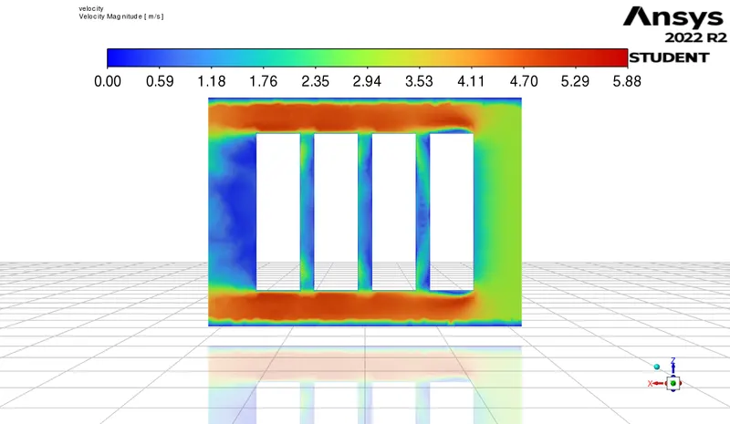
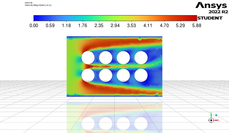
6. result
| Mesh length 3, gap 6 velocity 3 | Mesh length 5, gap 6 velocity 3 |
|
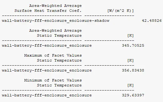 |
# transient
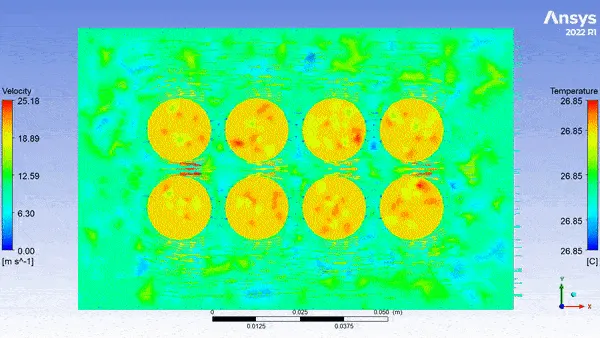
We have also performed the transient case study for the gap value of 4mm and velocity, 10 m/s to
visualise the change in temperature w.r.t. time.
Conclusion:-
1. higher will the veloity of air higher will be the heat rejected from the battery.
| 3m/s | 5m/s | 10m/s | |
| htc(W/m^2Kk | 35.35 | 47.81 | 69.31 |
| average temp(k) | 358.82 | 339.65 | 322.88 |
| maximum(k) | 381.54 | 352.90 | 329.35 |
| minimum(k) | 35.35 | 322.38 | 324.86 |
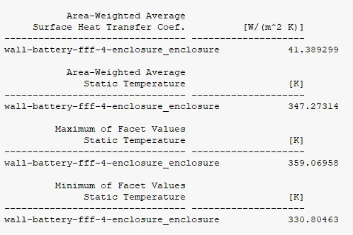
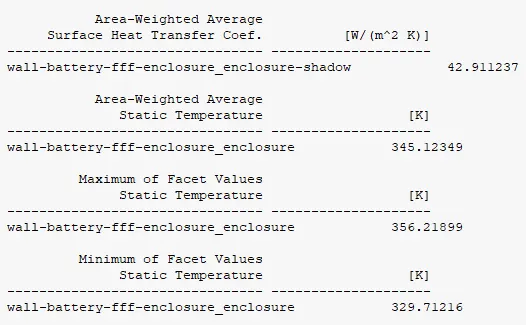
2. larger wiill the gap between battery cell higher will be the heat rejected from the battery.
| 2mm | 4mm | 6mm | |
| htc(W/m^2Kk | 35.35 | 41.38 | 42.911 |
| average temp(k) | 358.82 | 347.27 | 345.12 |
| maximum(k) | 381.54 | 359.06 | 356.21 |
| minimum(k) | 355.35 | 330.80 | 329.71 |
we can see that from battery gap from 2 to 4 mm we can see a large changes but when we compare 4 and 6mm there is no such variation observed.
we cannot increase gap between battery more because it will increase the space as well as battery weight.
3. when we perform mesh independent study we always found good result with finner mesh
Refrences
https://cfdflowengineering.com/battery-cooling-techniques-in-electric-vehicle