Week 10 - Simulating Combustion of Natural Gas.
Notice: - After the analysis, the size of the file is more, but in the challenge submission time it is not supported because of its large so I am sharing the google drive link please download from the link.
Link: https://drive.google.com/file/d/16AwdQObzW-0aTD0Jd8tCNdA40bl2iUNz/view?usp=sharing
Aim
Perform a combustion simulation on the combustor model using methane as fuel.
Objective
Part I
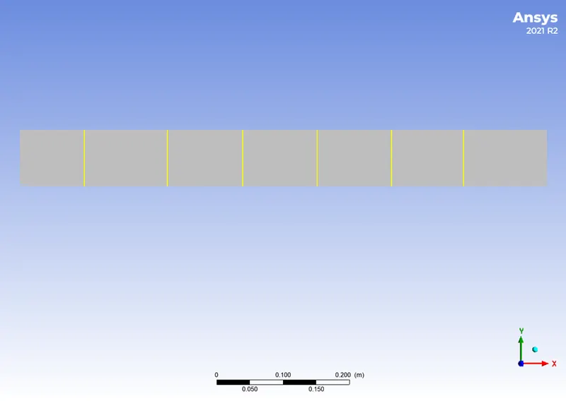
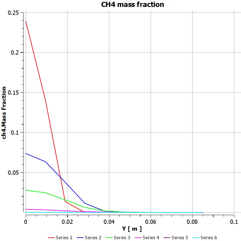
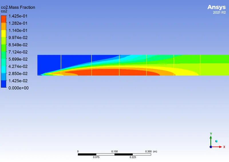
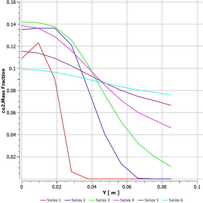
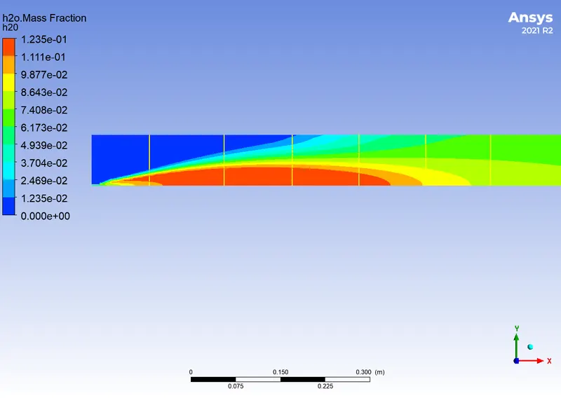
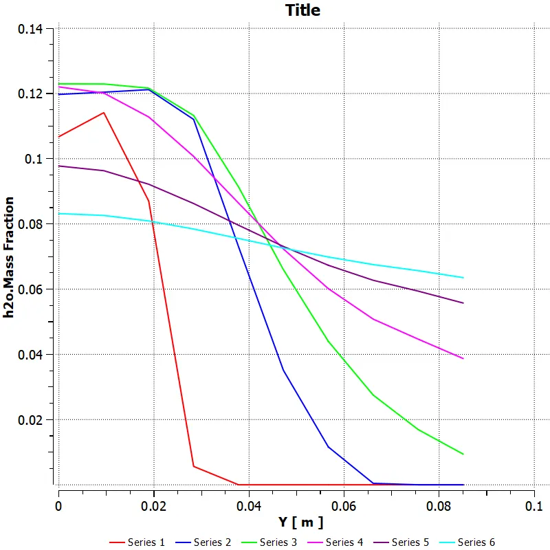
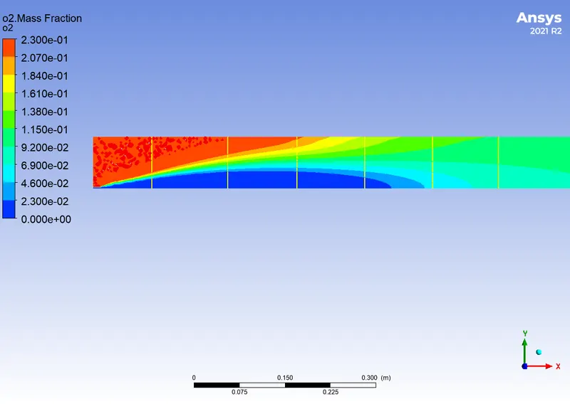
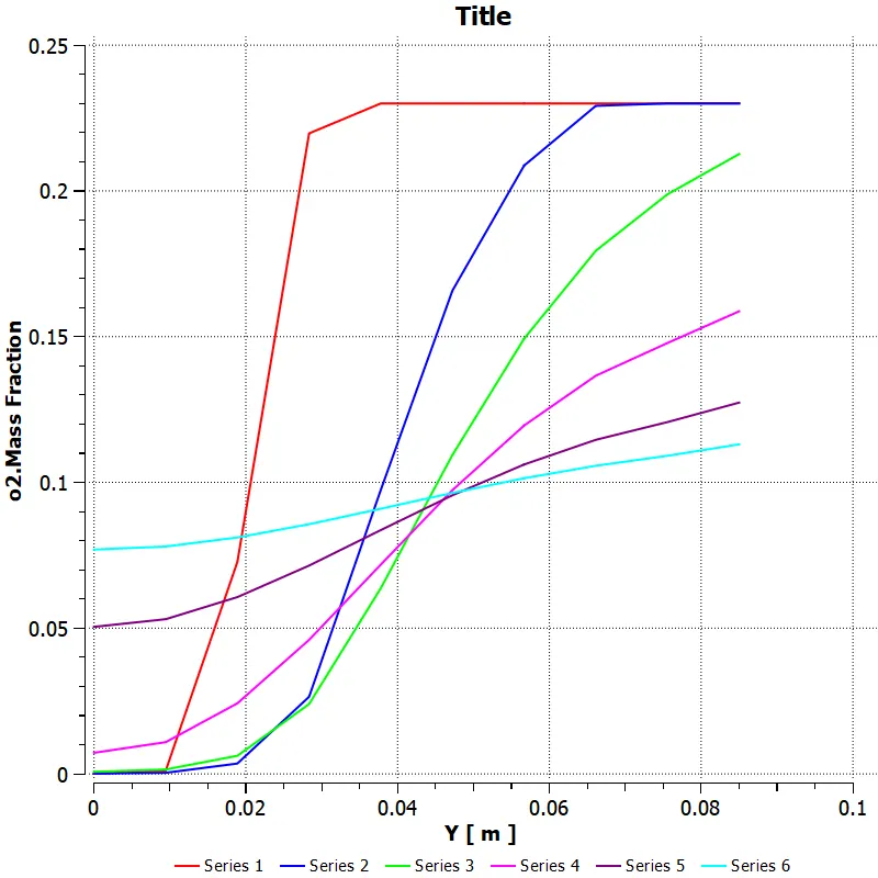
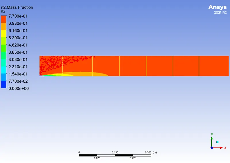
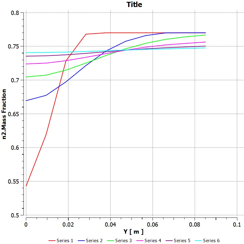
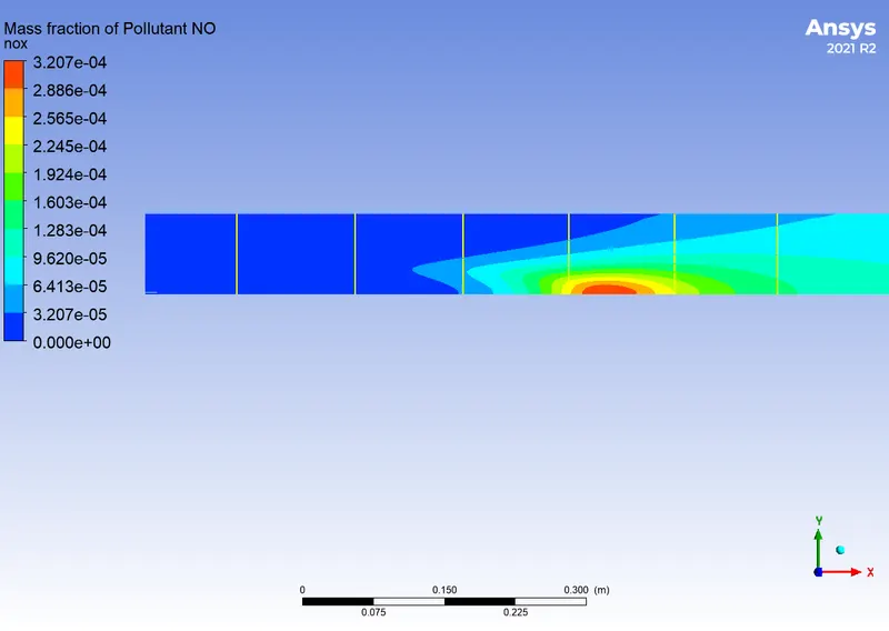
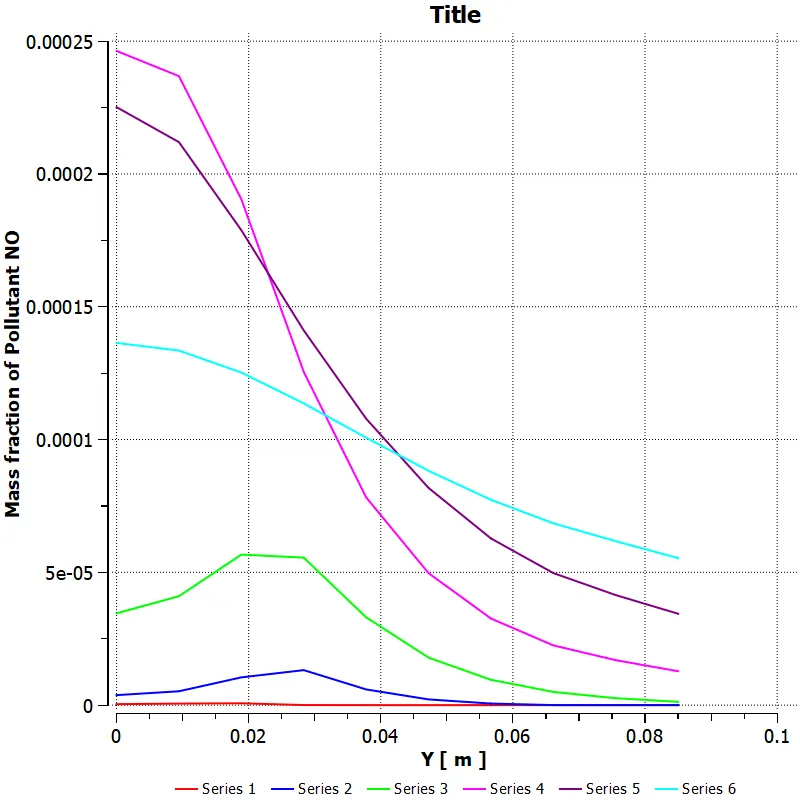
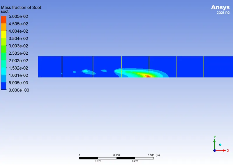
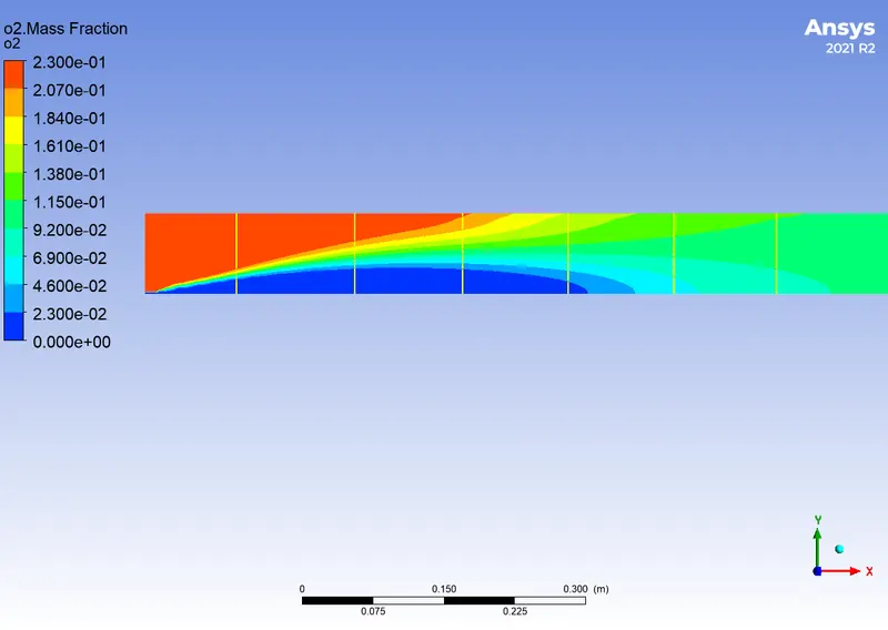
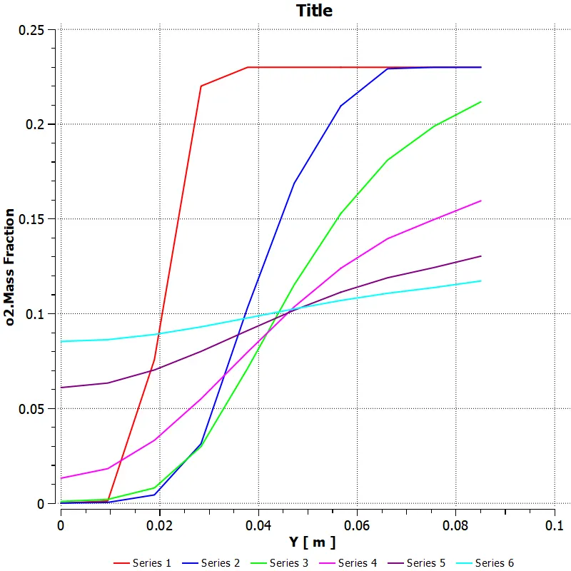
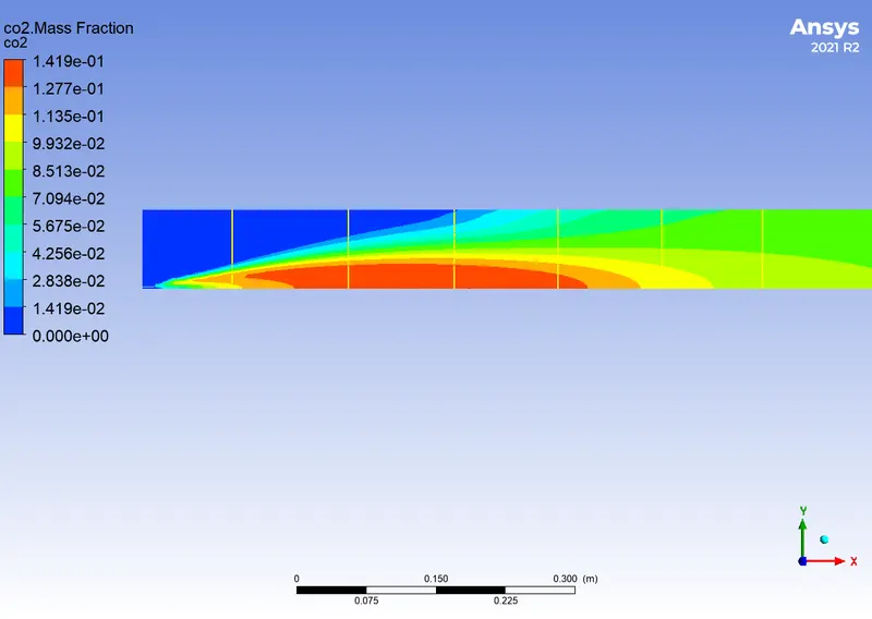
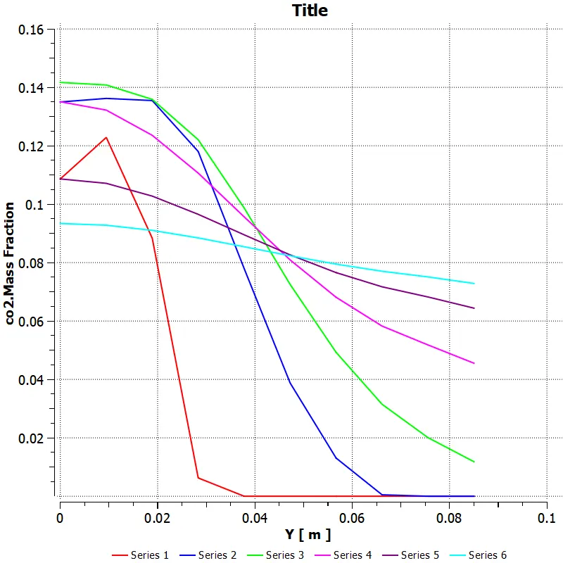
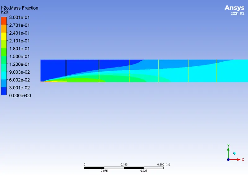
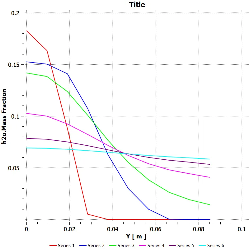
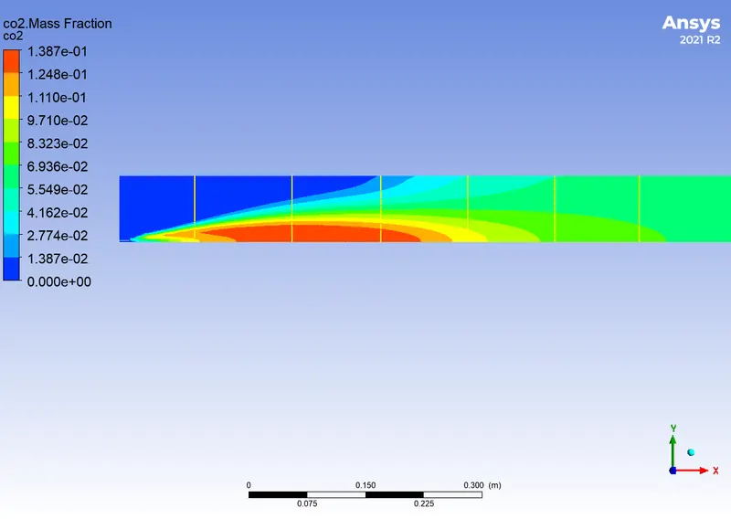
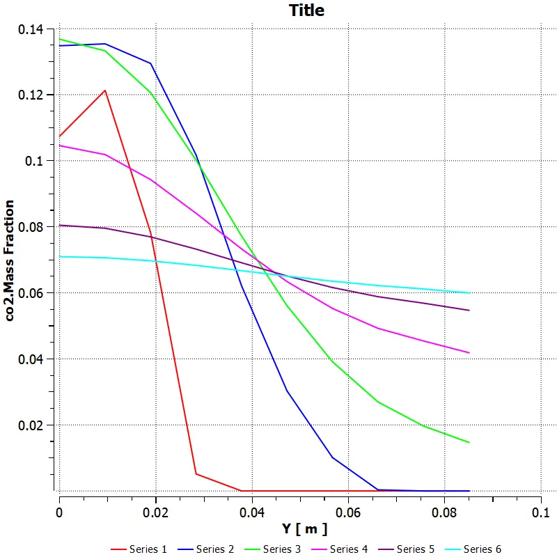
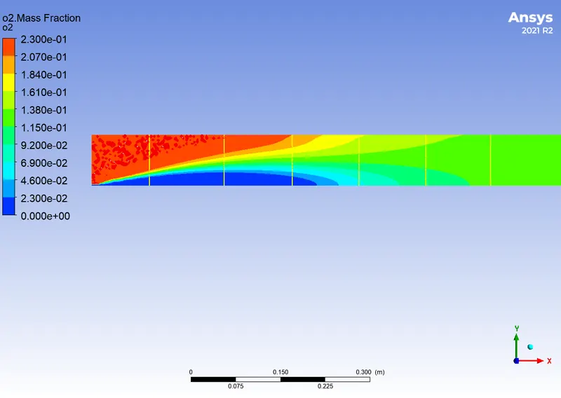
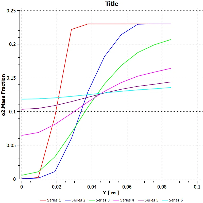
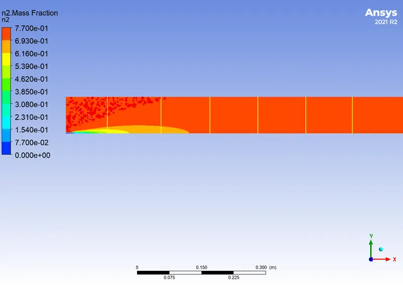
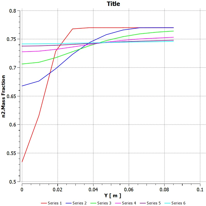
Perform a combustion simulation on the combustor model and plot the variation of the mass fraction of the different species in the simulation using line probes at different locations of the combustor as shown in Fig. You need to plot for CO2, H2O, CH4, N2, O2, NOx emissions & Soot formation.
Part II
As you must have observed from the above simulation, the Nox and soot are getting formed at the outlet of the combustor. The such formation has harmful effects on the environment and humans. The stringent government norms also demand the least formation of Nox and soot and to satisfy those requirements, you need to check the effect of adding water to the fuel.
In this part, you need to add the water content in the fuel from 5% to 30% by mole and observe the effect of it on the results. It is necessary to provide line plots and contours to prove your claim.
Introduction
A fuel (the reductant) and an oxidant, typically atmospheric oxygen, undergo a high-temperature exothermic redox chemical reaction that results in oxidized, frequently gaseous products and a mixture known as smoke. Since a flame only appears when substances undergoing combustion evaporate, combustion does not always result in fire, but when it does, a flame is a distinctive sign of the event. The heat from a flame may be enough energy to make the reaction self-sustaining even though the activation energy must be overcome to start combustion. A convoluted series of simple radical reactions frequently occur during combustion. Endothermic pyrolysis is the process that turns solid fuels like wood and coal into gaseous fuels that can be burned to generate the heat needed to create new solid fuels. A flame or a blazing incandescent light is frequently produced when combustion is hot enough. A straightforward illustration is provided by the reaction that occurs when hydrogen and oxygen combine to form water vapor, frequently utilized as rocket fuel. This reaction decreases the enthalpy and releases 242 kJ/mol of heat.

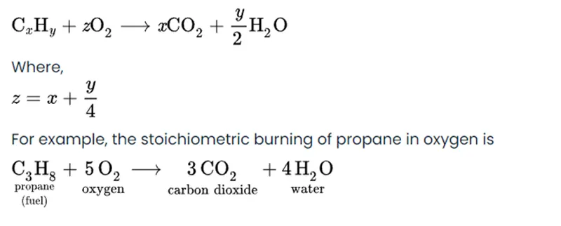
Stoichiometric combustion o a hydrocarbon in oxygen:
The chemical equation for the stoichiometric combustion of a hydrocarbon in oxygen is:
Chemical kinetic
The area of physical chemistry that deals with comprehending the speeds of chemical processes is known as chemical kinetics, sometimes known as reaction kinetics. Contrast that with thermodynamics, which focuses on the direction in which a process takes place but says nothing about the rate of that process. Chemical kinetics is the study of how experimental conditions affect a chemical reaction's rate and reveal details about its mechanism and transition stages. It also involves the development of mathematical models that may be used to represent the properties of a chemical reaction.
Chemical reaction model
Physical knowledge is transformed into a mathematical formulation via chemical reaction models, which may then be used to simulate real-world chemical engineering problems computationally. The versatility of studying chemical processes under various circumstances is made possible by computer simulation. Convection, diffusion, and reaction source conservation equations for each species involved in the reaction must be solved when modelling it.
Series transport equation

Si is the rate of addition from the dispersed phase and the user-defined source, and Ri is the net rate of formation of species I through a chemical reaction. Ji is the species I diffusion flux, which is different in laminar and turbulent flows and results from concentration gradients. Computational fluid dynamics also considers the effects of turbulent diffusivity in turbulent flows. The total of the reaction sources over the NR reactions among the species is used to calculate the net source of chemical species I owing to reaction, Ri, which appeared as the source term in the species transport equation.
Reaction models
Laminar finite rate model
The Arrhenius formulas are used by the laminar finite rate model to compute the chemical source terms, and turbulence fluctuations are not taken into account. Due to the non-linear Arrhenius chemical kinetics, this model produces a correct answer for laminar flames but an inaccurate one for turbulent flames, where turbulence significantly impacts the rates of chemical reactions. For combustion with minor turbulence variations, such as supersonic flames, this model may, nonetheless, be accurate.
Eddy dissipation model
The eddy dissipation model is a turbulent-chemistry reaction model that is based on the work of Magnussen and Heritage. The majority of fuels burn quickly, and turbulence mixing regulates the reaction's overall rate of speed. Turbulence slowly blends the fuel and oxidizer into the reaction zones of the non-premixed flames, where they burn rapidly. In premixed flames, the turbulence gradually combines the hot products and cool reactants in the reaction zones, where the reaction proceeds quickly. When this occurs, the combustion is considered to be mixing-limited, and it is safe to ignore the intricate and frequently unknowable chemical dynamics. According to this model, the large-eddy mixing time scale controls the chemical reaction. Anytime the flow is turbulent, combustion begins. The combustion can begin without an igniting source. The reactant is supposed to start burning as soon as it enters the computation model, which is a weakness of this model because, in reality, the reactant takes some time to reach the ignition temperature to start the combustion. This sort of model is valid for non-premixed combustion.
Factors affecting reaction rate:
- Natural reactants
- Temperature
- Concentration
- Catalysts
- Pressure
- Absorption of light
- Physical state
- Surface is of solid state
Application
A chemical reaction is described by mathematical models. Chemists and chemical engineers can use kinetics to better comprehend and characterize chemical processes like food degradation, microbial development, stratospheric ozone decomposition, and the chemistry of biological systems. These models can also be used to maximize product yield, more effectively segregate products, and get rid of by-products that are bad for the environment in chemical reactor design or modification. Kinetic models can be used to determine the temperature and pressure at which the largest yield of heavy hydrocarbons into gasoline will occur when performing catalytic cracking of heavy hydrocarbons into gasoline and light gas, for instance.
Solving and modelling approach
In the solving and modelling approach, we have to follow some steps
- Geometry
- Meshing
- Setup and calculation
- Result
Geometry
In geometry modelling, we import the 3D model of the combustion chamber. After importing the geometry, we split the geometry and copy the face and then paste the geometry. In the final, we will get the 2D geometry of the combustion chamber.

(Model of the combustion chamber)
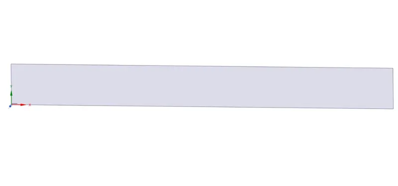
(2D geometry of combustion chamber)
Meshing
In the meshing, we have to take mesh size with 3mm element size. After meshing we have to create the name section as the air inlet, fuel inlet, axis, wall and outlet. After creating the name section have to update the mesh.
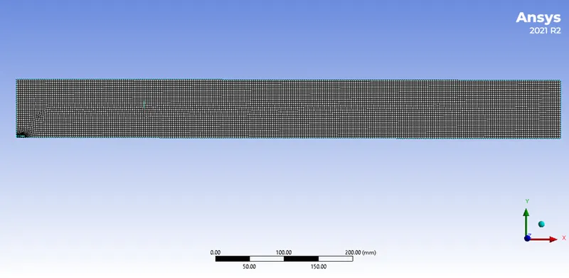
(Meshing of the combustion chamber)
Setup and calculation
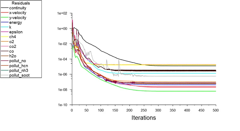
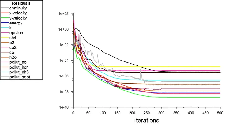
In the setup, we have to take pressure-based steady state with axisymmetric, in the method we use the k-epsilon standard model. In the special model species transport with volumetric reaction and use methane-air 2step mixture with eddy dissipation injection.
In the boundary condition, we use an air inlet with 0.5m/s velocity with O2 mass fraction of 0.23 and the fuel inlet of 80m/s. In the fuel species mass fraction, we use H2O 5% to 30% with the fuel methane. And calculate with hybrid initialization.
Result
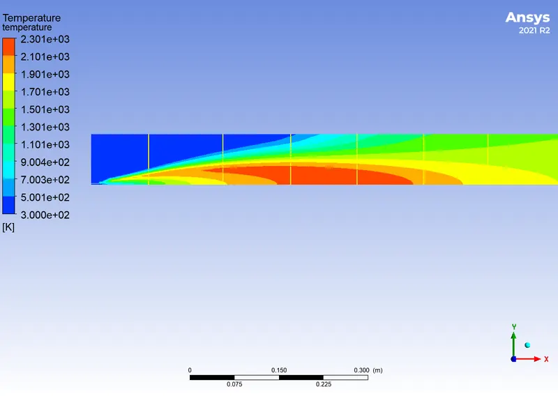
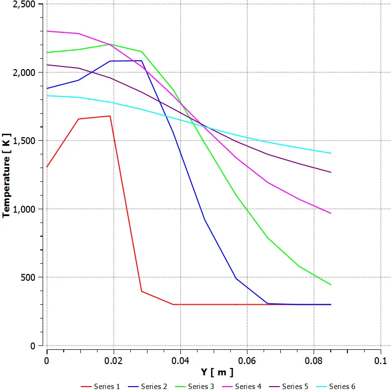
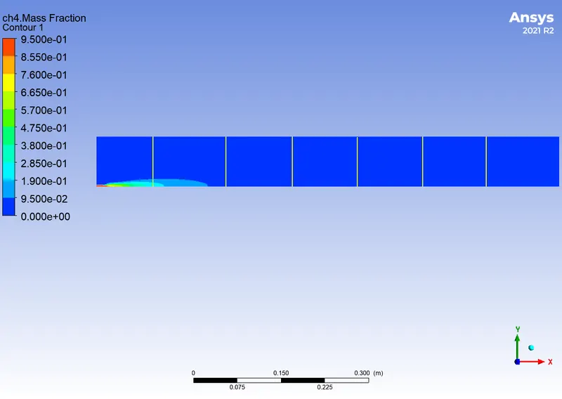
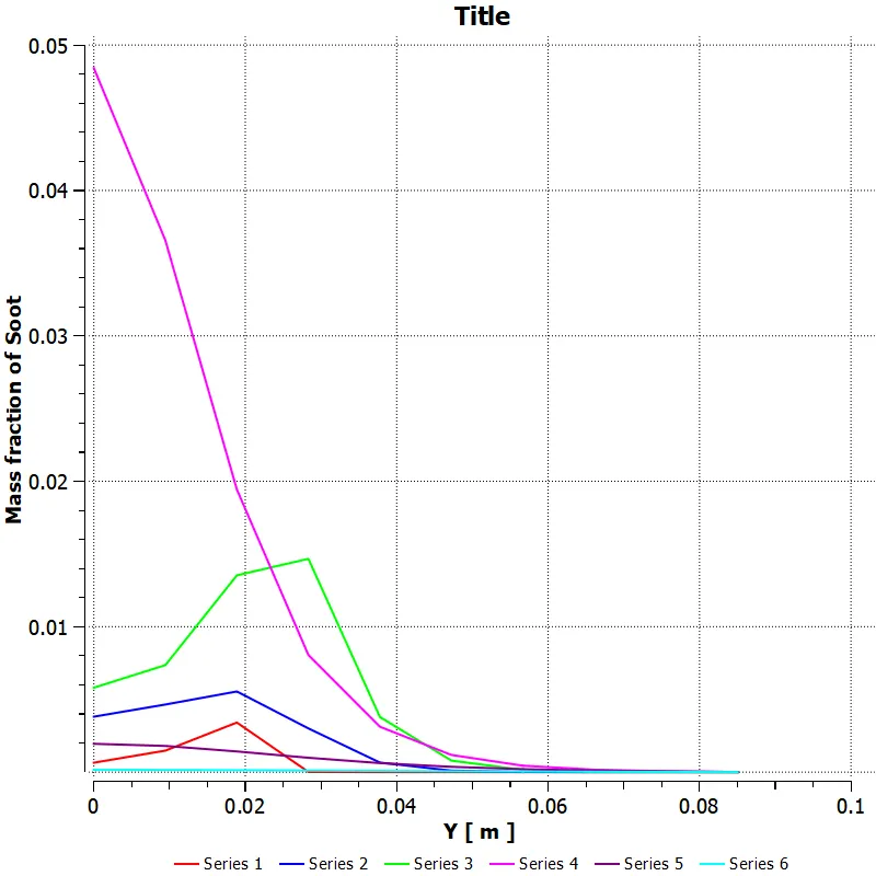
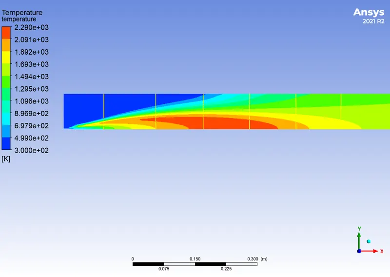
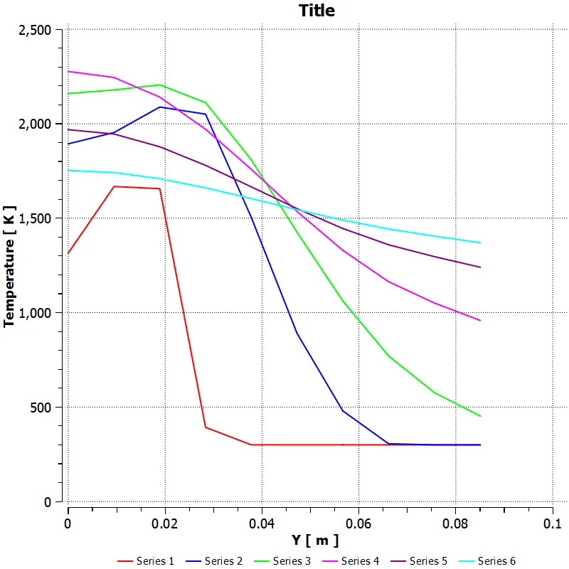
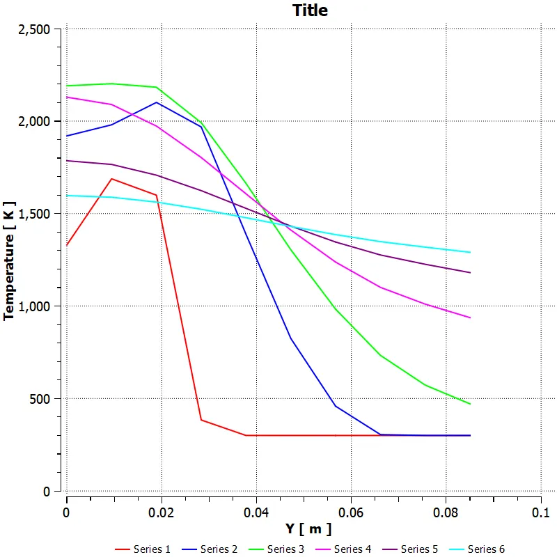
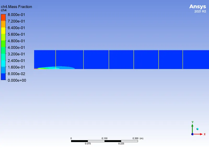
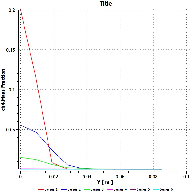
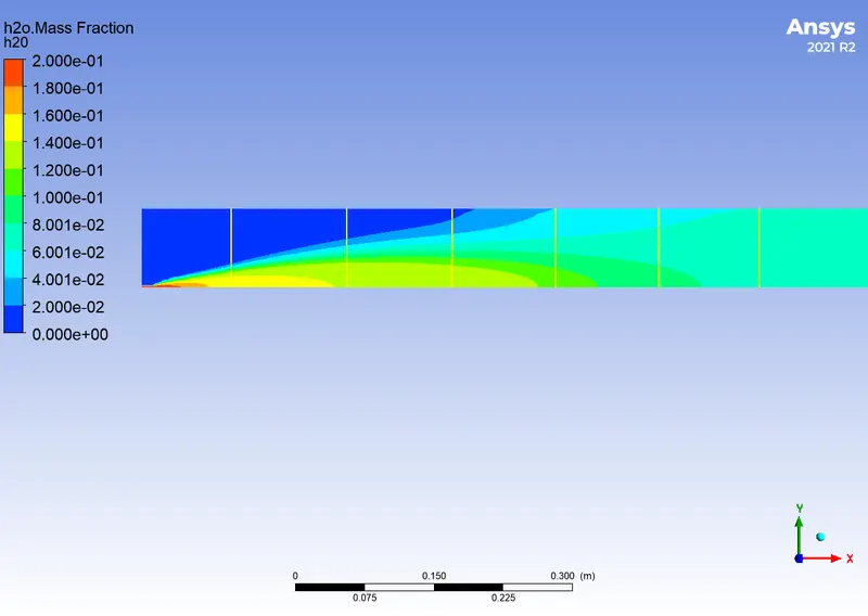
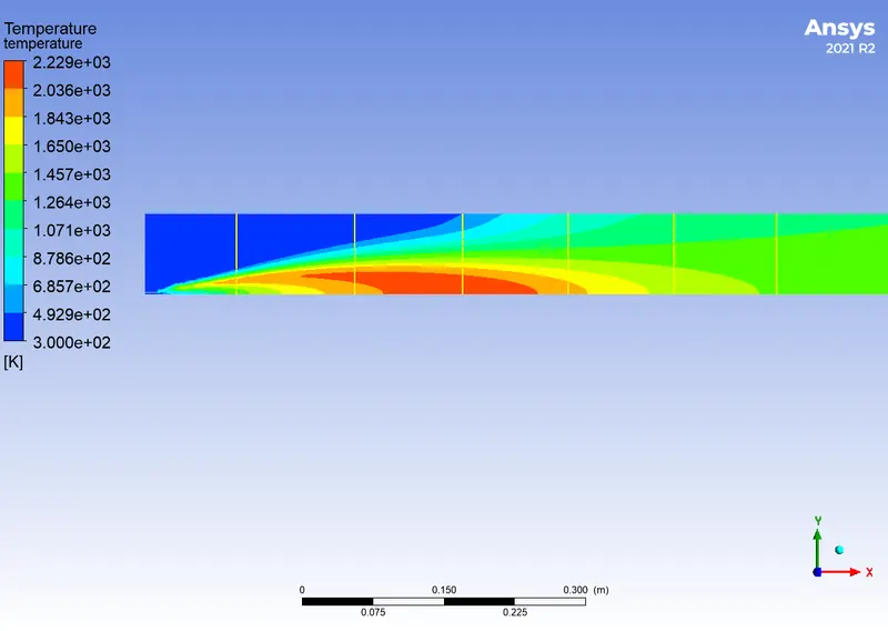
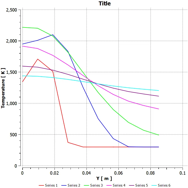
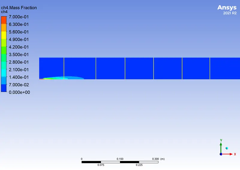
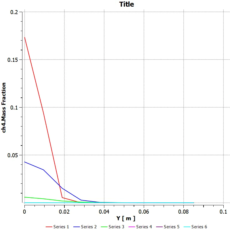
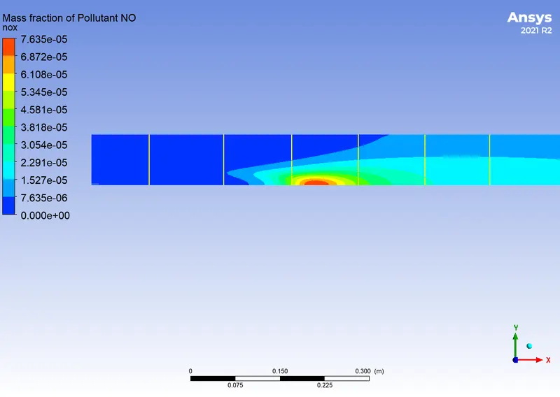
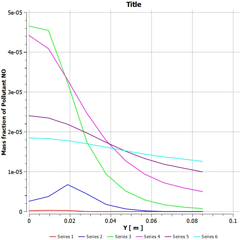
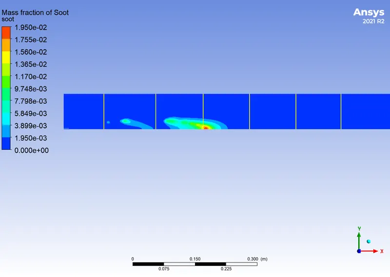
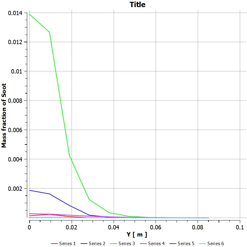
In the result section, we plot the contour of the temperature and other species like CO2, CH4, H2O, N2, O2, NOX and soot formation also plot the chart in the 6 stages of these using 5% to 30% H2O in the fuel with 4 cases.
Case-1 with 5% H2O in the fuel
Case-2 with 10% H2O in the fuel
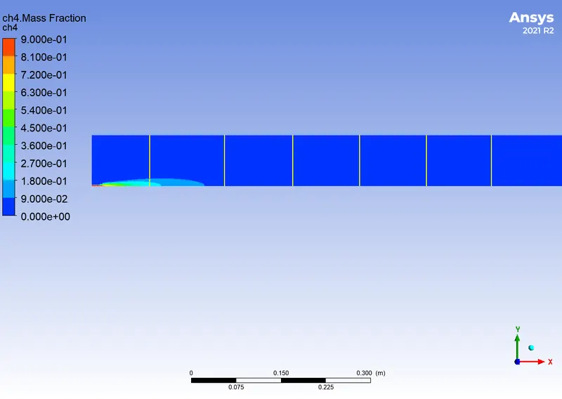
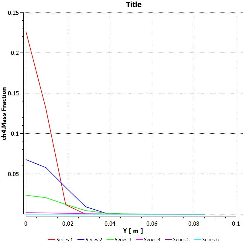
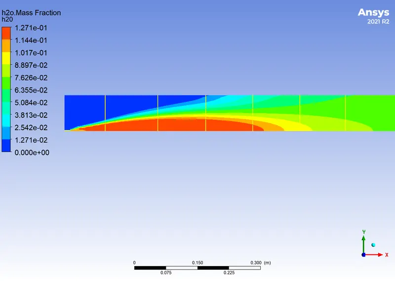
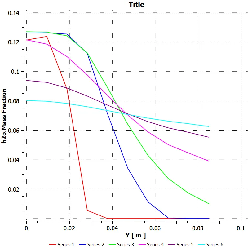
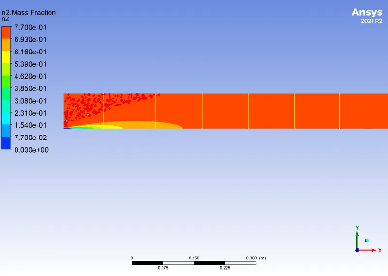
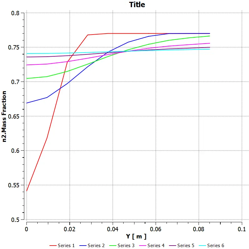
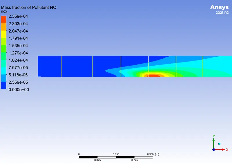
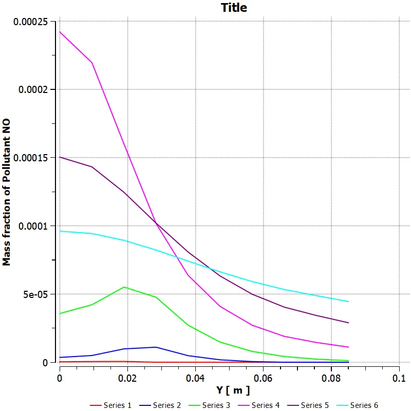
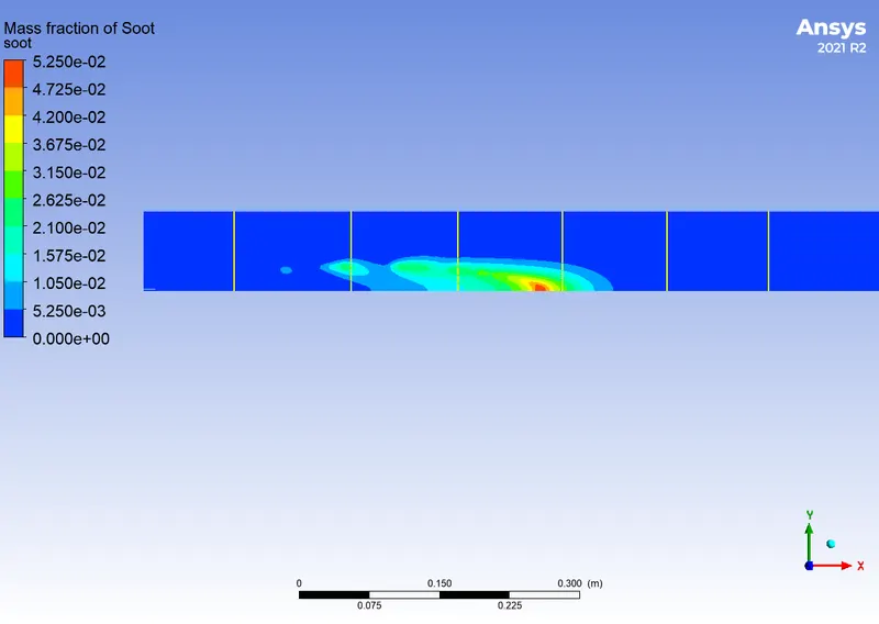
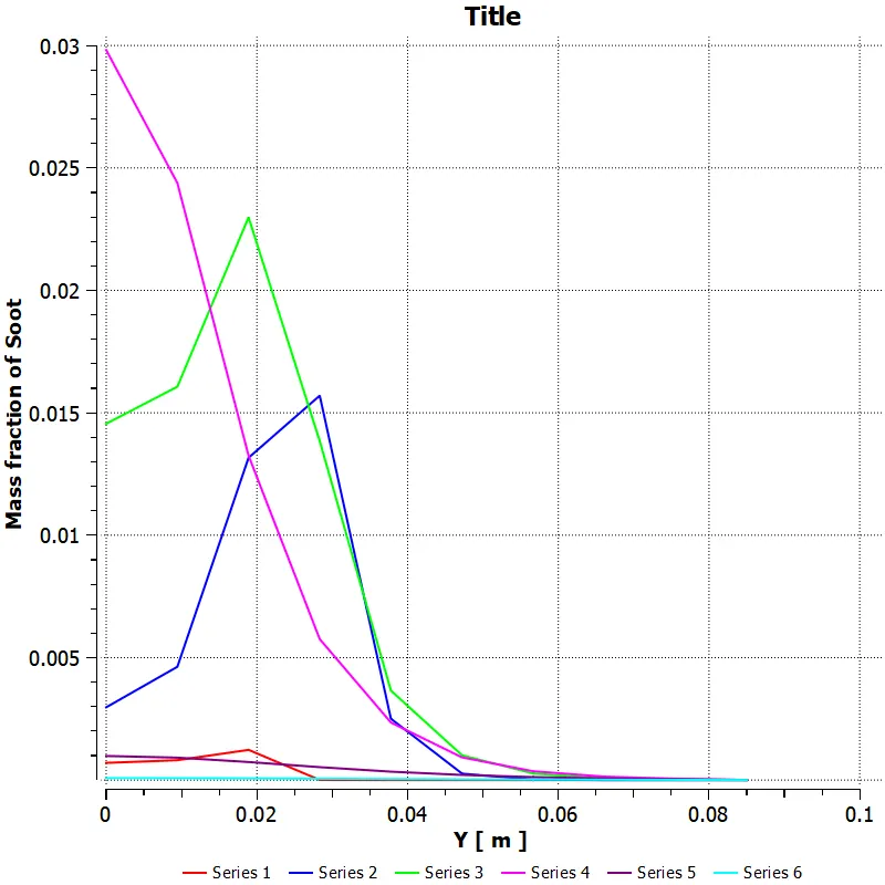
Case-3 with 20% H2O in the fuel
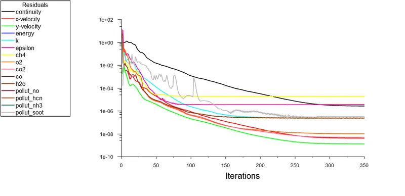
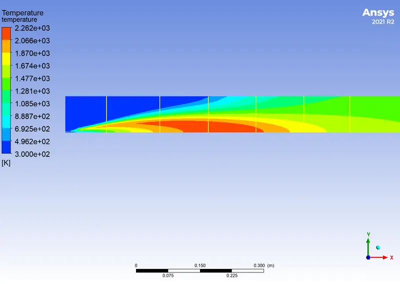
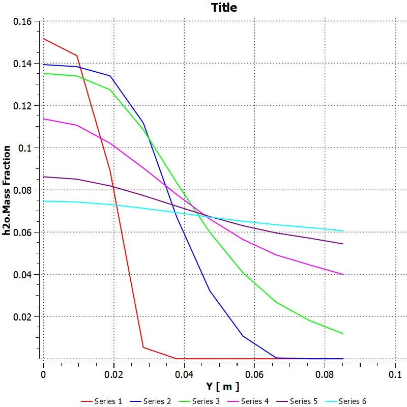
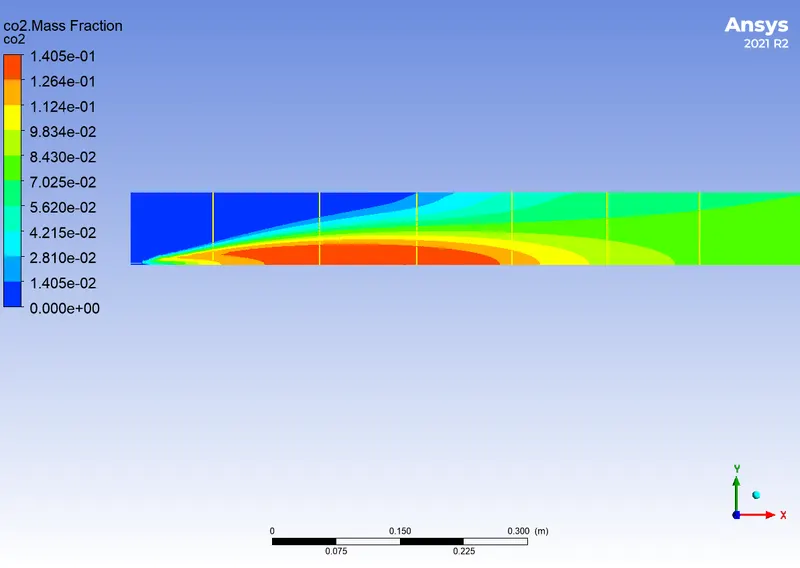
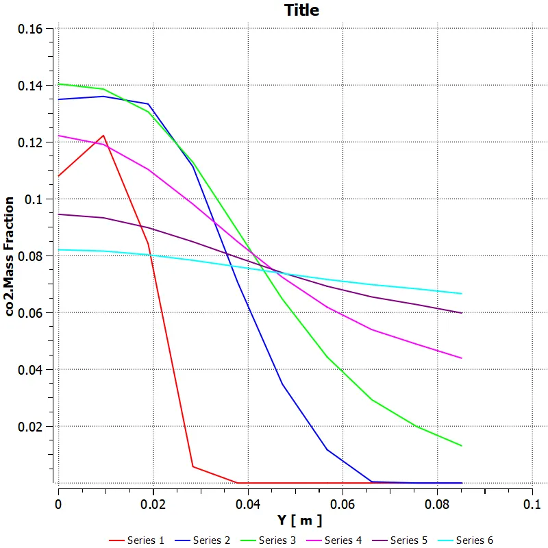
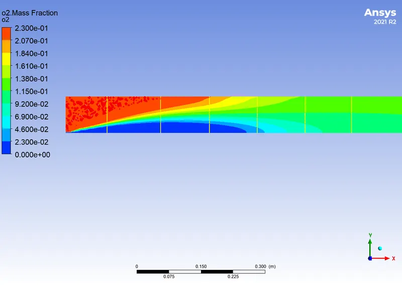
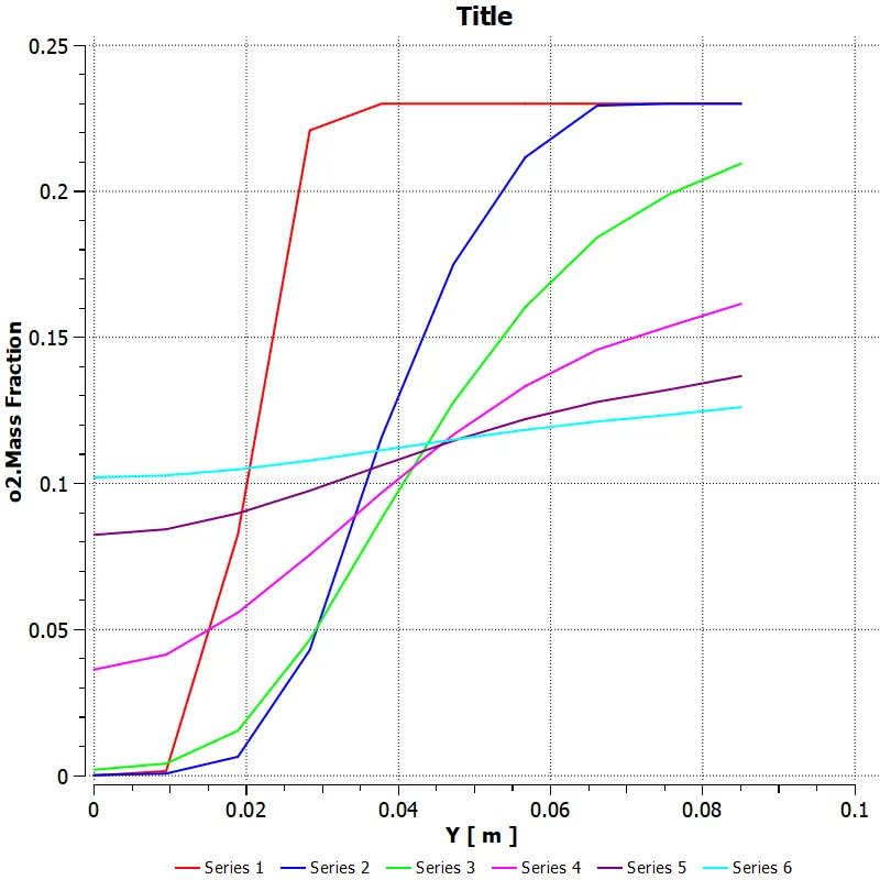
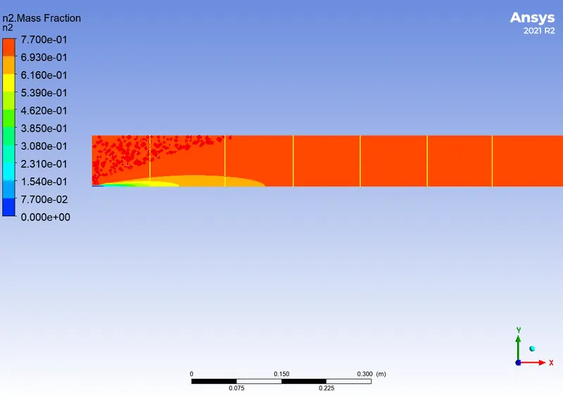
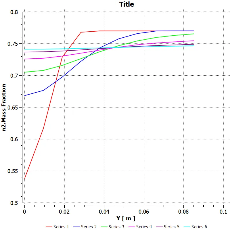
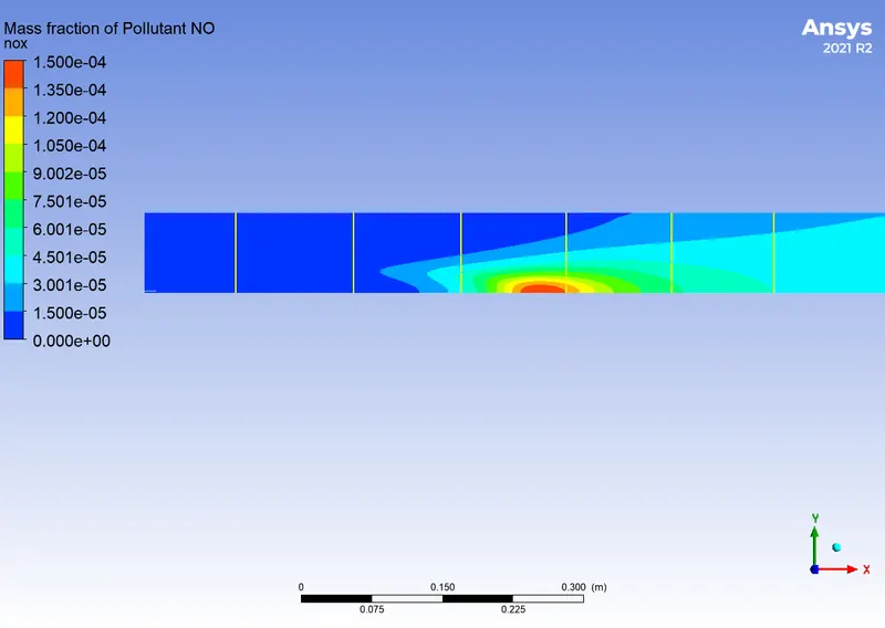
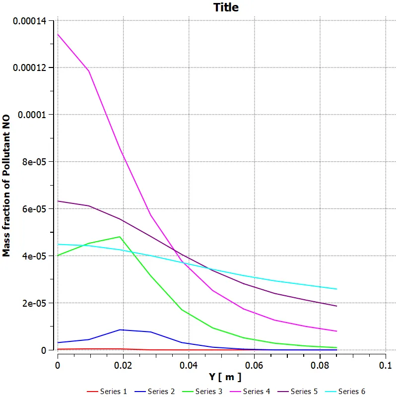
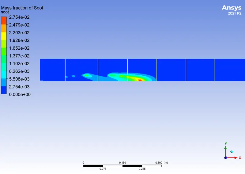
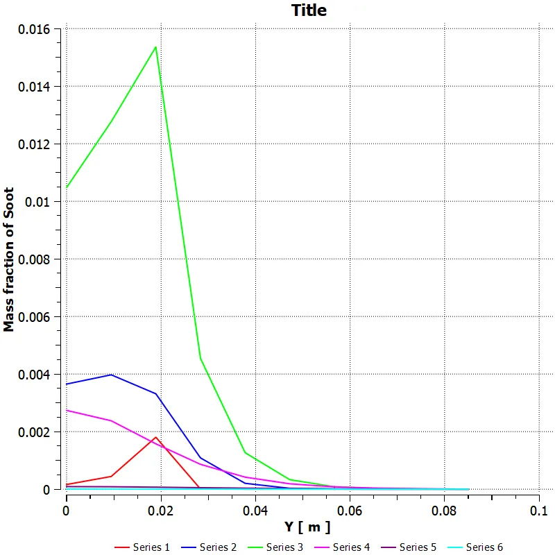
Case-4 with 30% H2O in the fuel
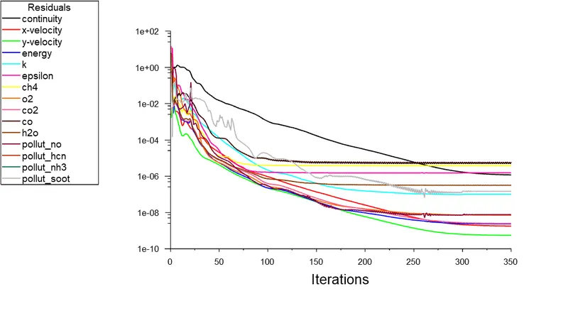
Conclusion
Comparing NOX and soot levels in the different water addition
|
% of water addition in fuel |
The ratio of methane and water (CH4: H2O) |
Mass fraction of NOX |
Mass fraction of soot formation |
|
5% |
0.95:0.05 |
8.9203e-05 |
1.0001e-05 |
|
10% |
0.9:0.1 |
6.6540e-05 |
5.1163e-06 |
|
20% |
0.8:0.2 |
3.4238e-05 |
4.7061e-07 |
|
30% |
0.7:0.3 |
1.5222e-08 |
4.5936e-08 |
It is clear from the preceding experiment and the statistics in the table that adding more water results in lower NOx emissions and soot deposits. However, as there is less incomplete combustion, combustion efficiency decreases. The research report makes a few predictions on the soot reduction in relation to the addition of water. Equivalence ratio reduction or enlistment Leaner combinations hence soot less than richer mixtures. The temperature increases of the unburned gas or, more specifically, the temperature increase of the flame over 1800 K. Soot will be reduced by higher temperatures than usual. reduction in flame temperature below 1600 K. Therefore, reducing soot requires very low combustion temperatures.
Reference
- Mazzei, Lorenzo, et al. “Modelling Soot Production and Thermal Radiation for Turbulent Diffusion Flames.” Energy Procedia, vol. 126, 2017, pp. 826–833., doi:10.1016/j.egypro.2017.08.266.
- Chybowski, Leszek, et al. “An Overview of Systems Supplying Water into the Combustion Chamber of Diesel Engines to Decrease the Amount of Nitrogen Oxides in Exhaust Gas.” Journal of Marine Science and Technology, vol. 20, no. 3, 2015, pp. 393–405., doi:10.1007/s00773-015-0303-8.
- Woodyard, Doug. “Exhaust Emissions and Control.” Pounder's Marine Diesel Engines and Gas Turbines, 2009, pp. 61–86., doi:10.1016/b978-0-7506-8984-7.00003-5.