Week 10 - Simulating Combustion of Natural Gas.
Aim: To perform a combustion simulation on the combustor model and plot the variation of the mass fraction of the different species in the simulation using line probes at different locations of the combustor.
Combustion:
Combustion is a chemical process in which a substance reacts rapidly with oxygen and gives off heat. The original substance is called the fuel, and the source of oxygen is called the oxidizer. The fuel can be a solid, liquid, or gas, although for airplane propulsion the fuel is usually a liquid. The oxidizer, likewise, could be a solid, liquid, or gas, but is usually a gas (air) for airplanes. For model rockets, a solid fuel and oxidizer is used.
During combustion, new chemical substances are created from the fuel and the oxidizer. These substances are called exhaust. Most of the exhaust comes from chemical combinations of the fuel and oxygen. When a hydrogen-carbon-based fuel (like gasoline) burns, the exhaust includes water (hydrogen + oxygen) and carbon dioxide (carbon + oxygen). But the exhaust can also include chemical combinations from the oxidizer alone. If the gasoline is burned in air, which contains 21% oxygen and 78% nitrogen, the exhaust can also include nitrous oxides (NOX, nitrogen + oxygen). The temperature of the exhaust is high because of the heat that is transferred to the exhaust during combustion. Because of the high temperatures, exhaust usually occurs as a gas, but there can be liquid or solid exhaust products as well. Soot, for example, is a form of solid exhaust that occurs in some combustion processes.
During the combustion process, as the fuel and oxidizer are turned into exhaust products, heat is generated. Interestingly, some source of heat is also necessary to start combustion. Gasoline and air are both present in your automobile fuel tank; but combustion does not occur because there is no source of heat. Since heat is both required to start combustion and is itself a product of combustion, we can see why combustion takes place very rapidly. Also, once combustion gets started, we don't have to provide the heat source because the heat of combustion will keep things going. We don't have to keep lighting a campfire, it just keep burning.
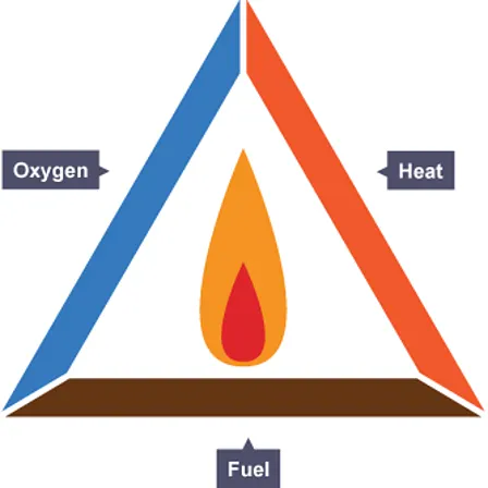
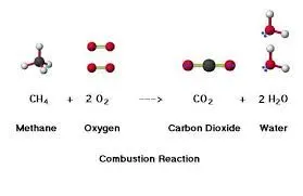
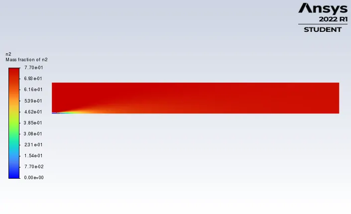
Nitrogen gas is not highly reactive i.e does not support combustion with other molecules in the atmosphere and is mainly present in air as N2 (78%).
Solving & modelling approach:
- Import the 3D combustor geometry in space claim.
- Convert the geometry into axisymmetric geometry by using split body by plane option.
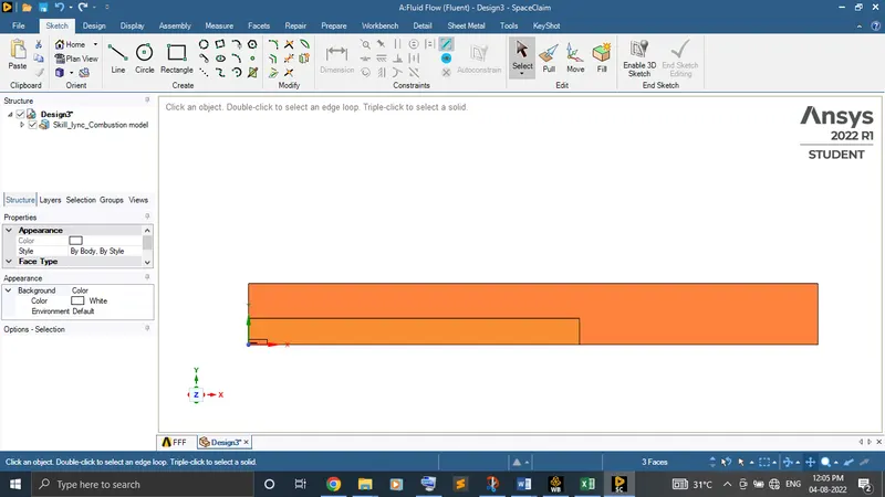
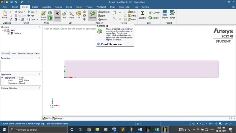
- Copy the surface of the front and paste in the new design to create the 2D surface and combine each individual surface into a single surface by using combine option. Finally, save the design.
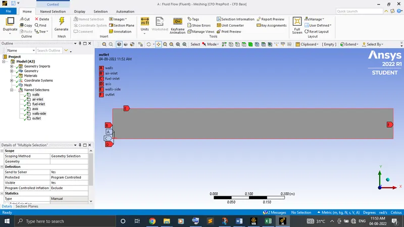
- Load the geometry in meshing. Do the named selections for the inlet (fuel & water), axis, walls, walls-side, and outlet. Mesh the geometry by choosing yes for the capture proximity with default gap factor.
- Do the necessary physics and boundary conditions setup in setup to converge the solution.
- Finally, compare the result of each case.
Pre-processing and solver setting:
Geometry:
Import the 3D combustor geometry in space claim.
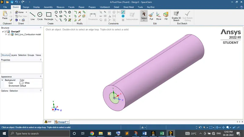
Convert the geometry into axisymmetric geometry by using split body by plane option.
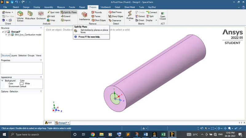

Copy the surface of the front and paste in the new design to create the 2D surface and combine each individual surface into a single surface by using combine option. Finally, save the design.
Meshing:
Load the geometry in meshing and do the named selections for the edges.
Do the mesh to the geometry for the following
Element size - 0.001 m
Sizing (Capture proximity) - yes (with default gap factor)
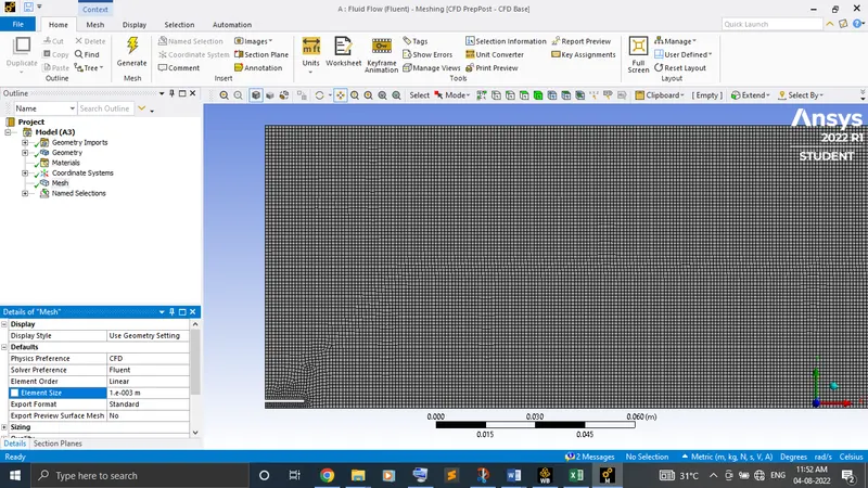
Nodes – 68327
Element - 67423
Setup:
Solver type - Steady state pressure based with axisymmetric planar
Model -
- Realizable, K-Epsilon viscous turbulence model with standard wall treatment.
- Energy equation - On
- Species transport - Reactions (Volumetric), Mixed properties (Methane-air), Option (inlet diffusion), Turbulence chemistry interaction (Eddy-dissipation)
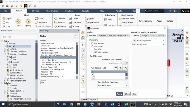
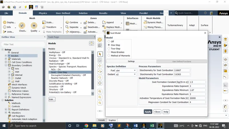
Boundary Conditions -
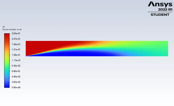
- Inlet (air) - Velocity (0.5 m/s), Species mass fraction of oxygen (0.23)
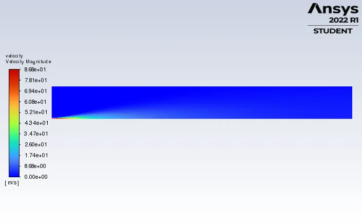
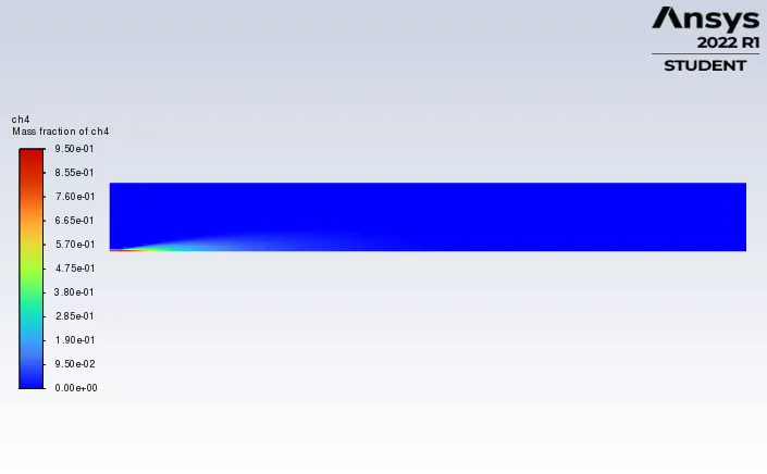
- Inlet (fuel) - Velocity (80 m/s), Species mass fraction of CH4 (1)
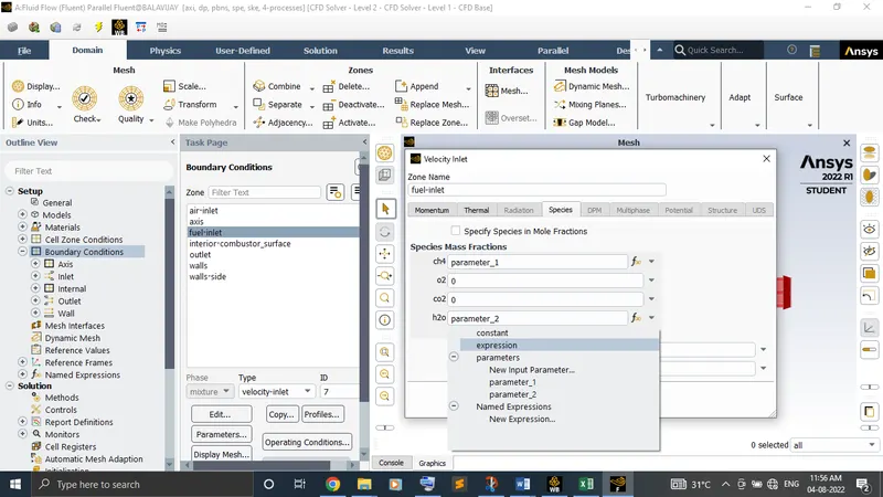
Initialize the standard initialization and run the calculation.
CFD Post:
Create the line probes to analyse the result of the mass fraction of the substances at different locations of the combustor.
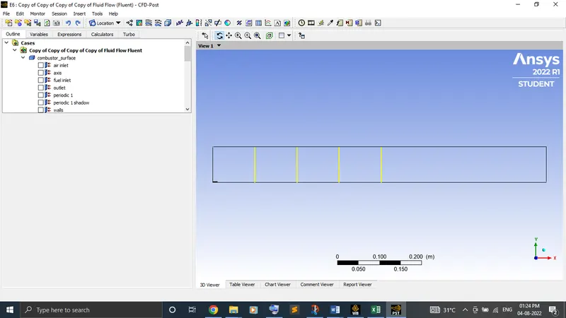
Results:
Part 1: Without water addition in the fuel
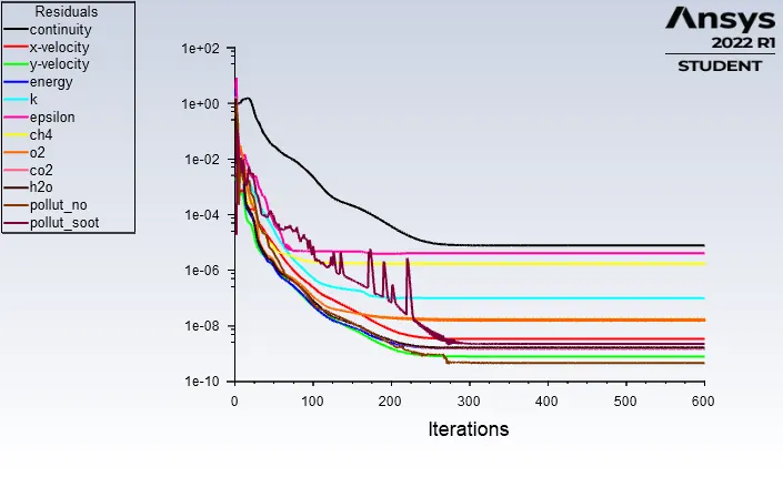
Residual plot:
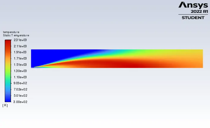
Temperature contour:
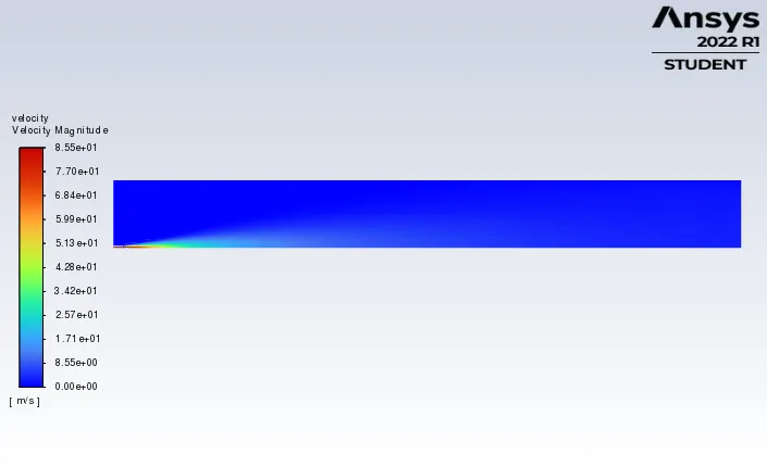
Velocity contour:
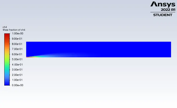
CH4 contour:
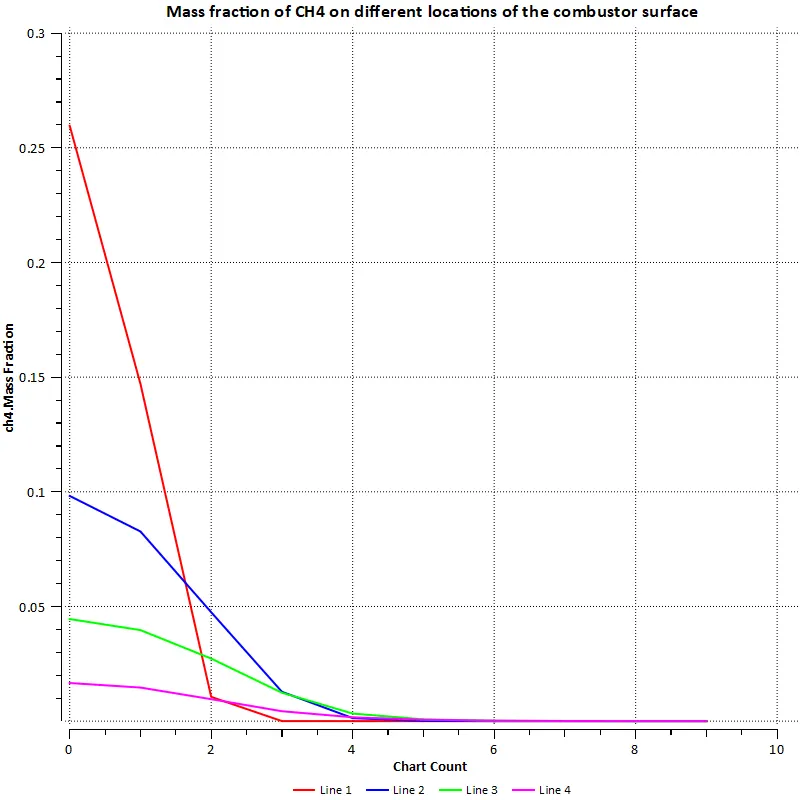
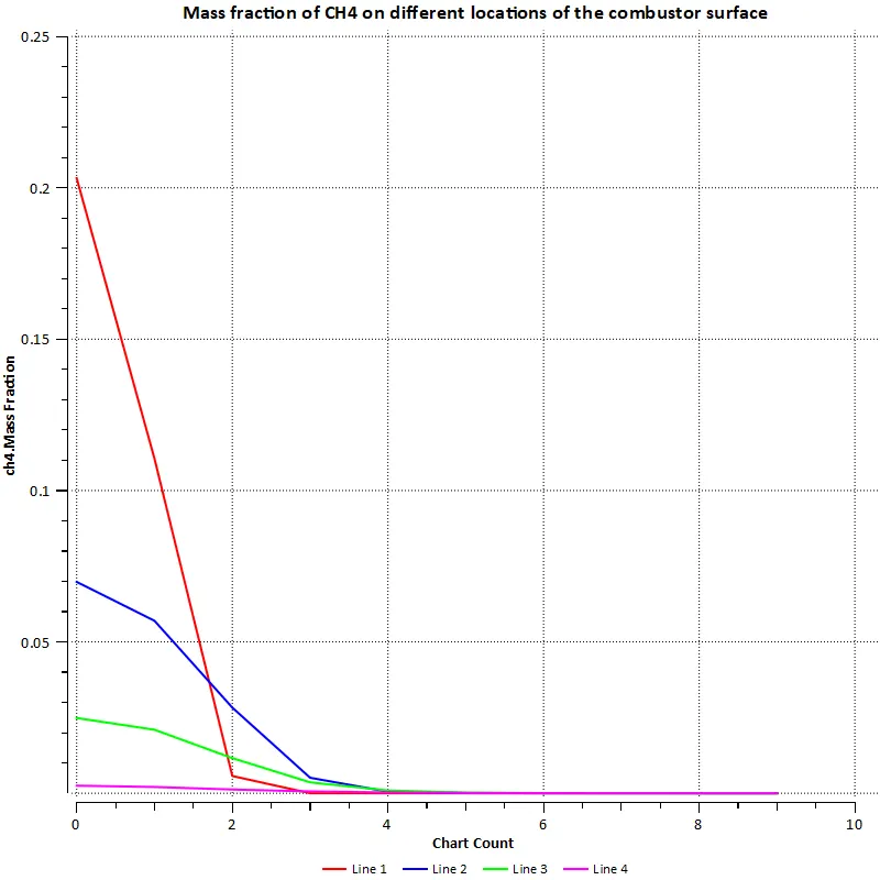
CH4 line plot:
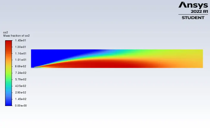
CO2 contour:
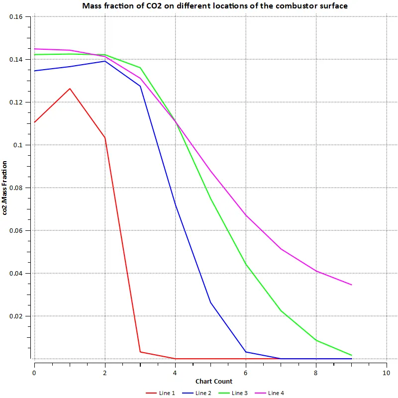
CO2 line plot:
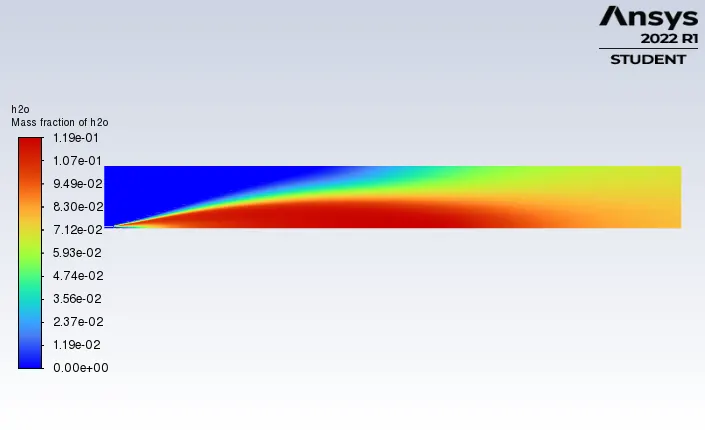
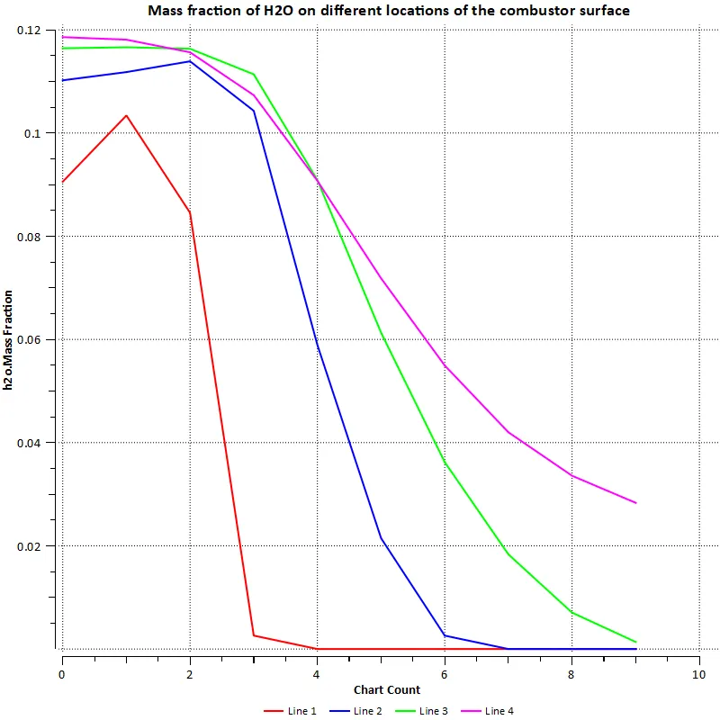
H2O contour:
H2O line plot
N2 contour:
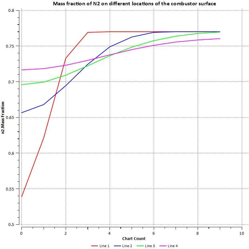
N2 line plot:
O2 contour:
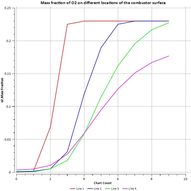
O2 line plot:
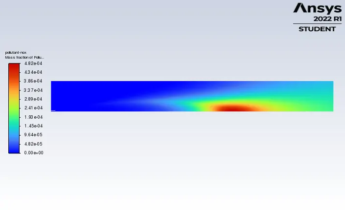
Pollutant NOx contour:
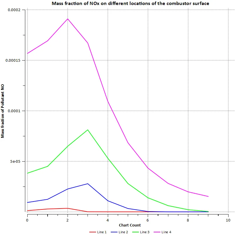
Pollutant NOx line plot:
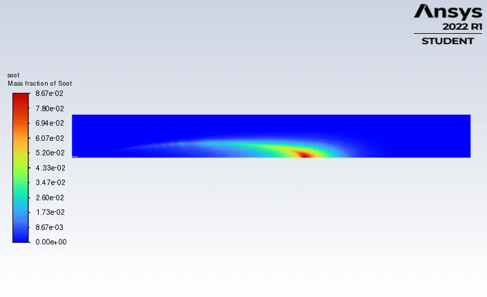
SOOT contour:
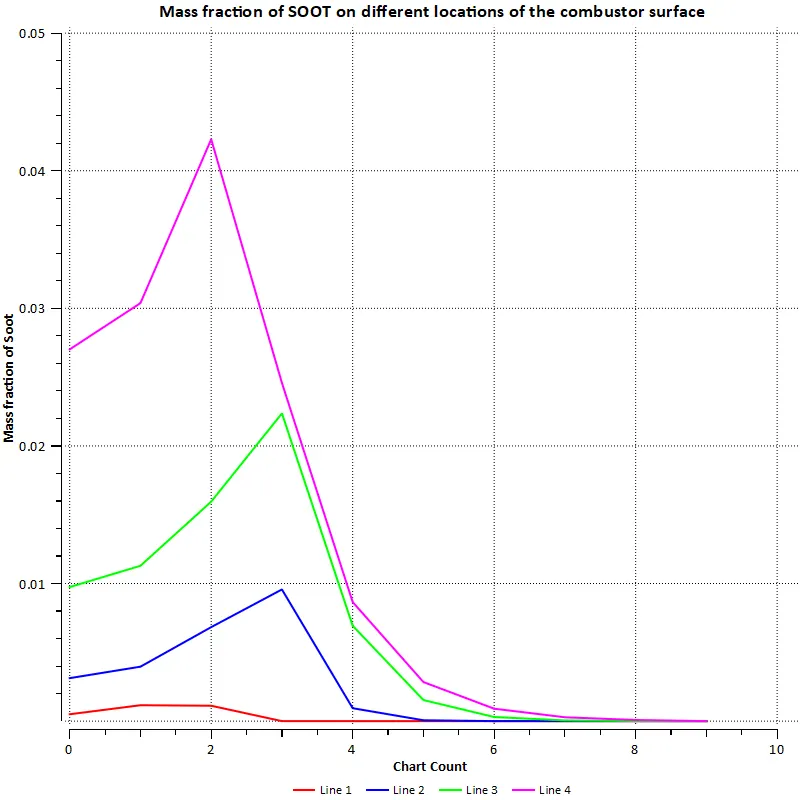
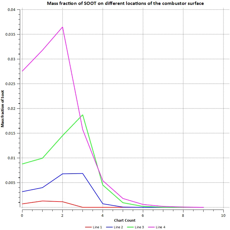
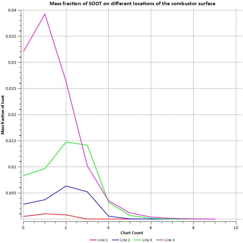
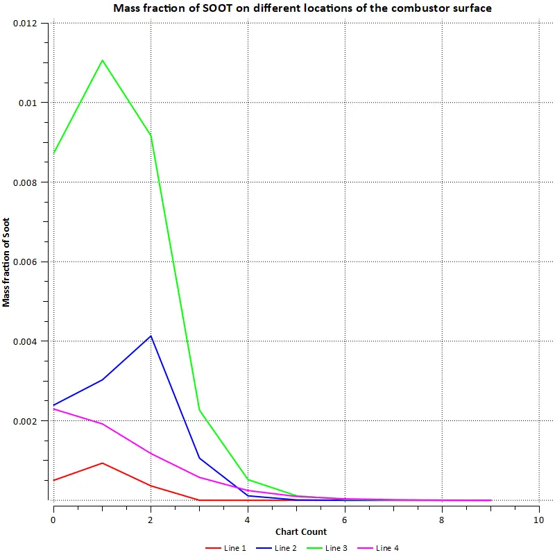
SOOT line plot:
Part 2:
Case 1: 5% addition of water in the fuel
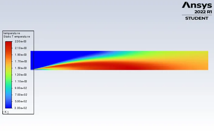
Temperature contour:
Velocity contour:
CH4 contour:
CH4 line plot:
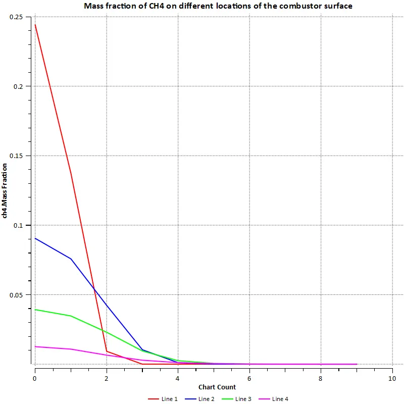
CO2 contour:
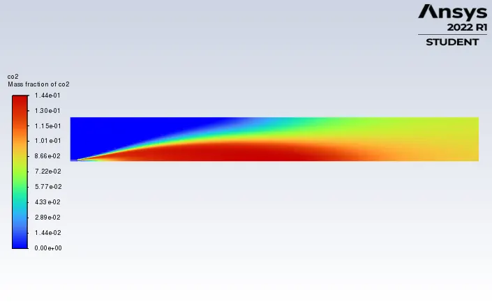
CO2 line plot:
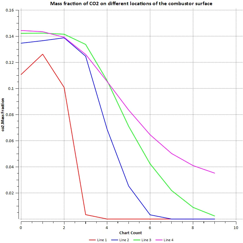
H2O contour:
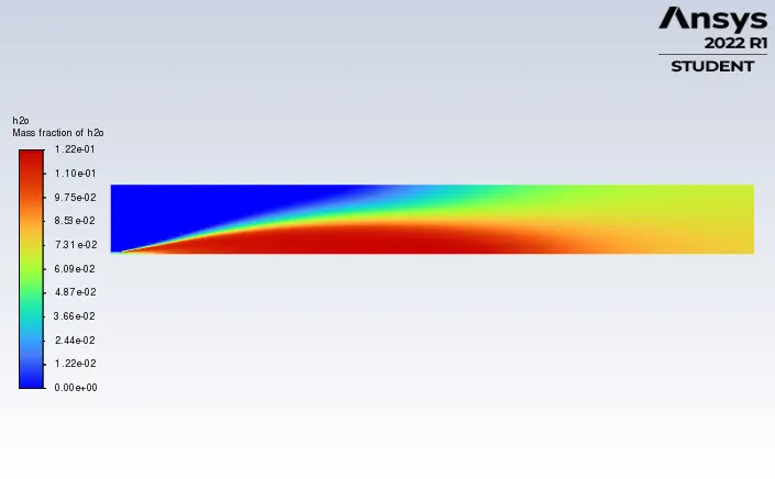
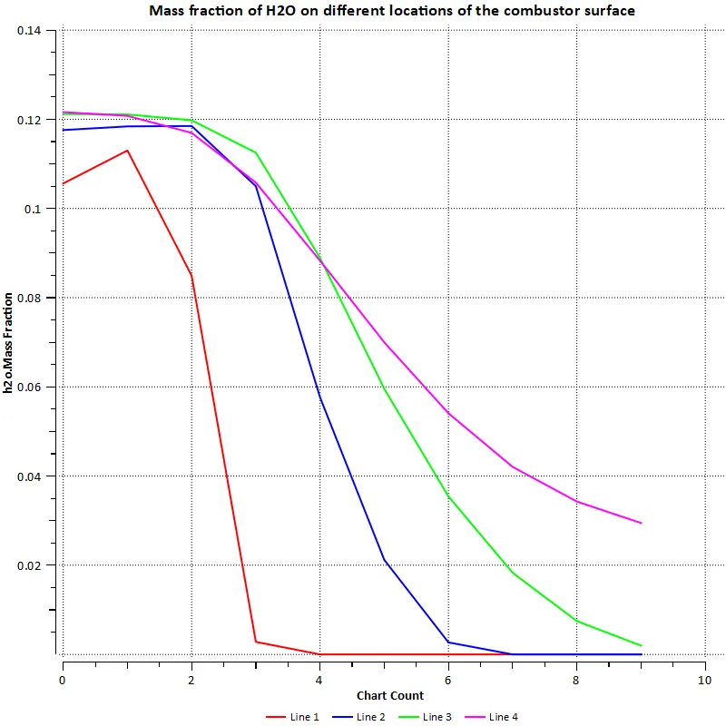
H2O line plot
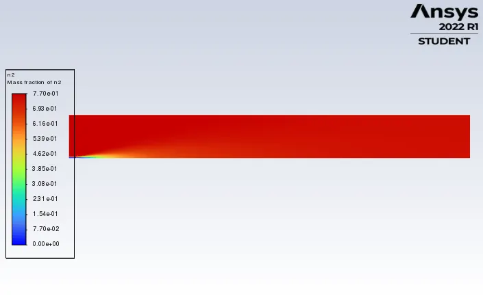
N2 contour:
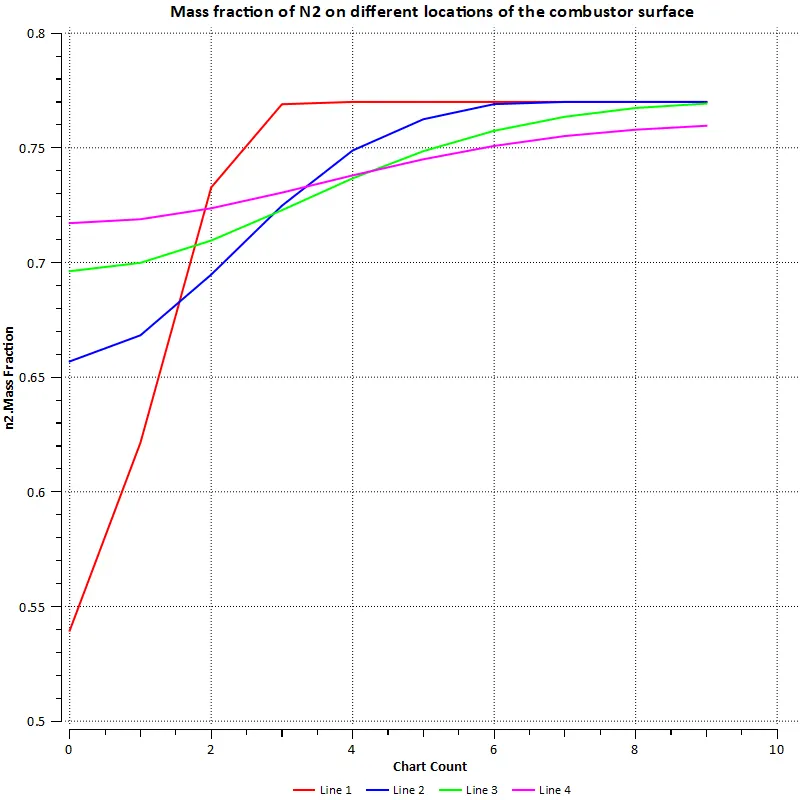
N2 line plot:
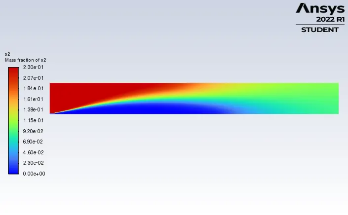
O2 contour:
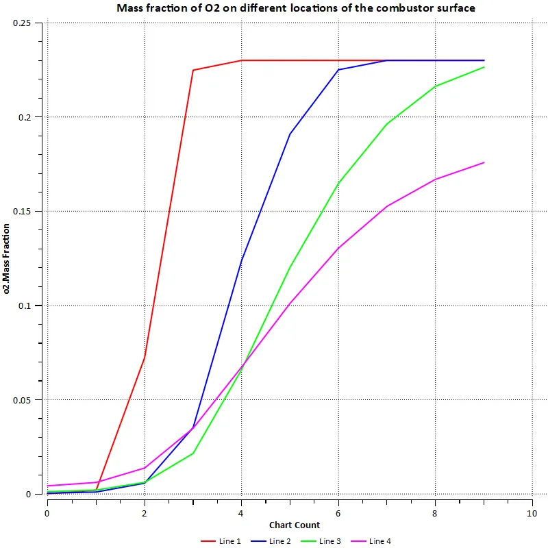
O2 line plot:
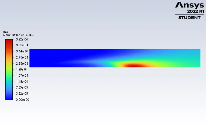
Pollutant NOx contour:
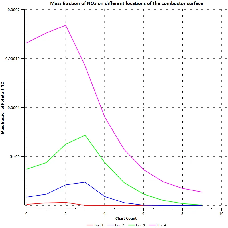
Pollutant NOx line plot:
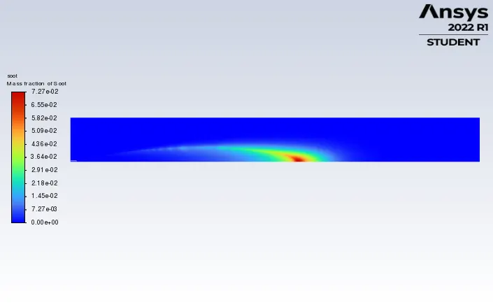
SOOT contour:
SOOT line plot:
Case 2: 10% addition of water in the fuel
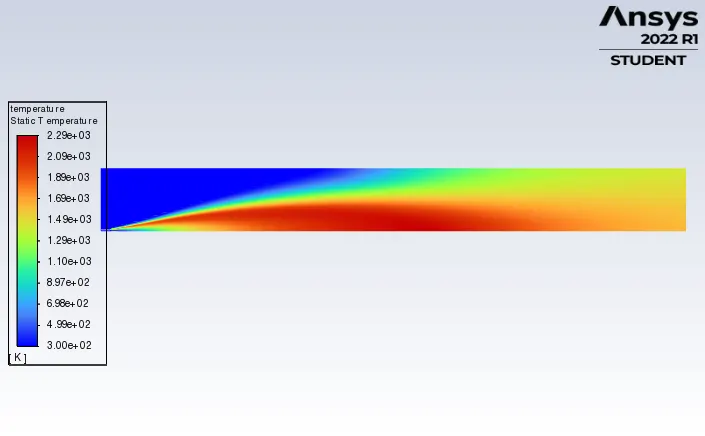
Temperature contour:
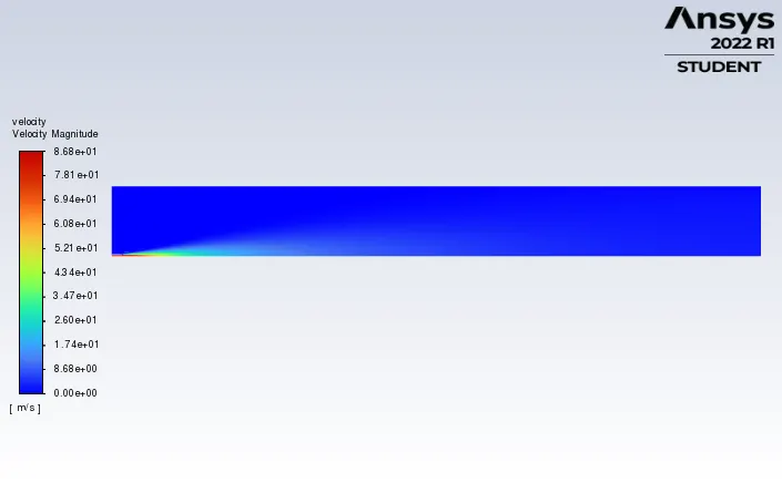
Velocity contour:
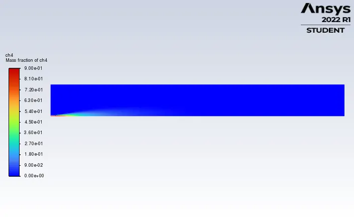
CH4 contour:
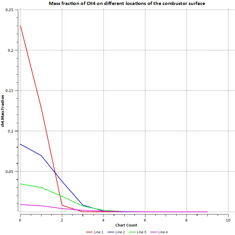
CH4 line plot:
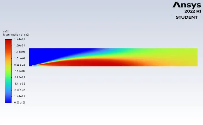
CO2 contour:
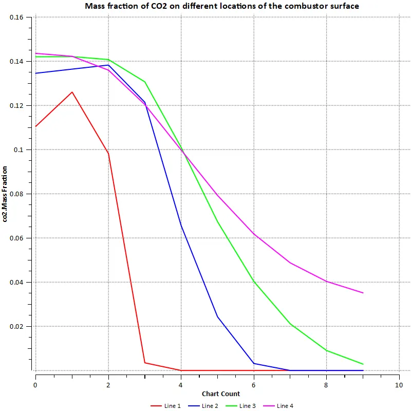
CO2 line plot:
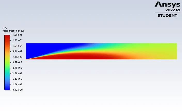
H2O contour:
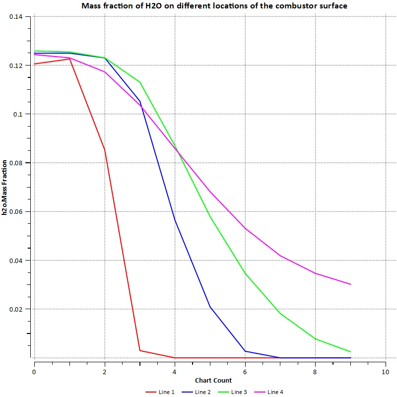
H2O line plot
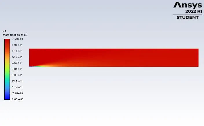
N2 contour:
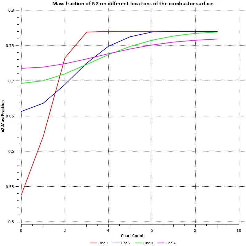
N2 line plot:
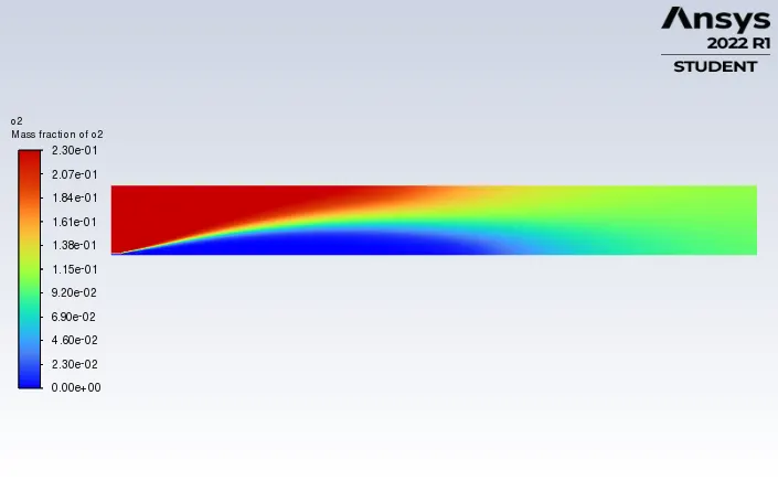
O2 contour:
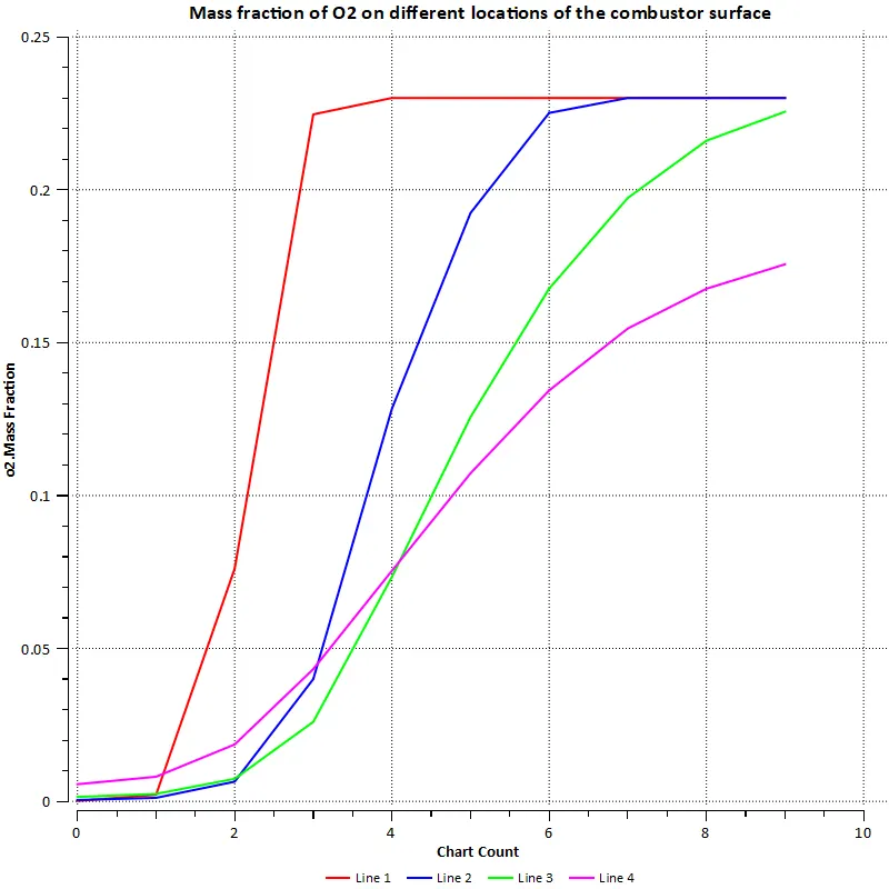
O2 line plot:
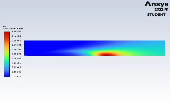
Pollutant NOx contour:
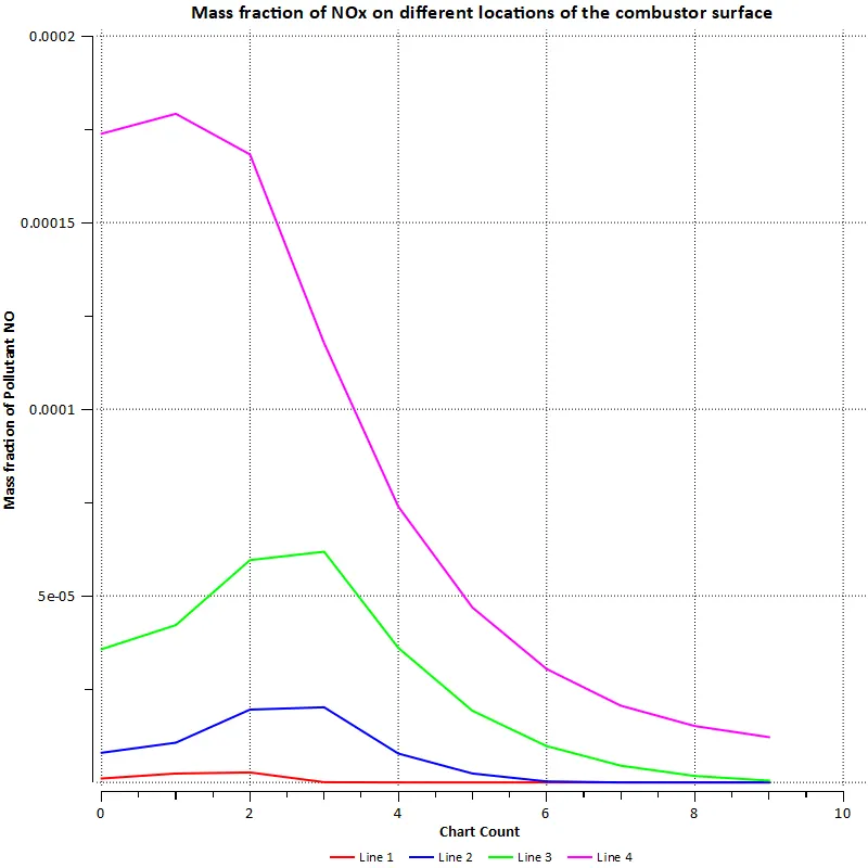
Pollutant NOx line plot:
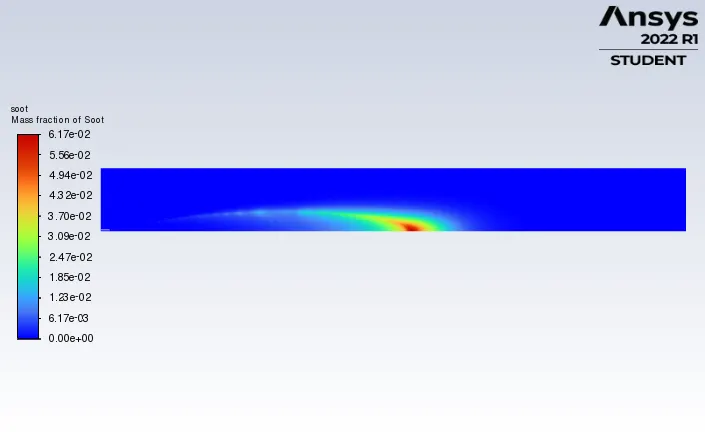
SOOT contour:
SOOT line plot:
Case 3: 20% addition of water in the fuel
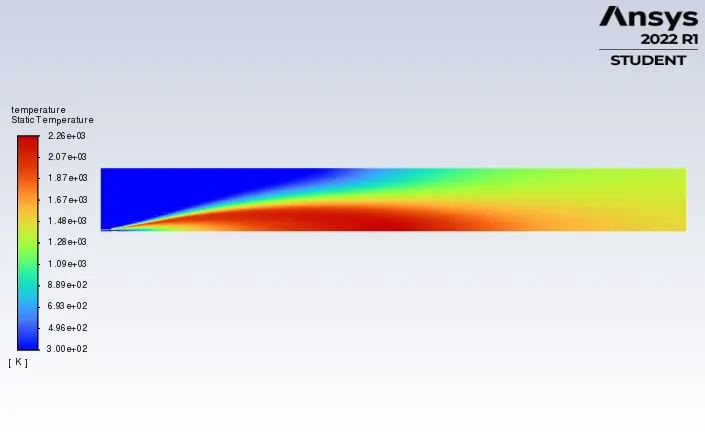
Temperature contour:
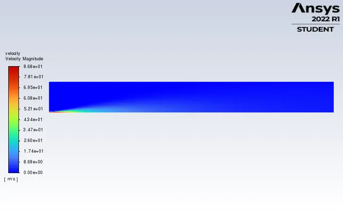
Velocity contour:
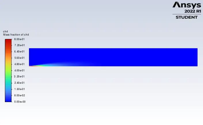
CH4 contour:
CH4 line plot:
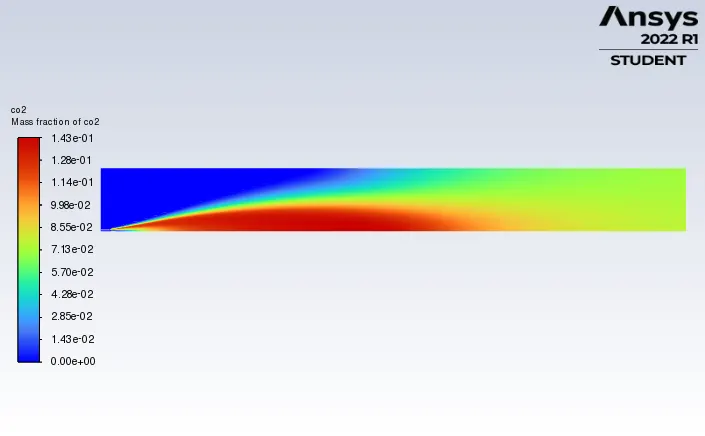
CO2 contour:
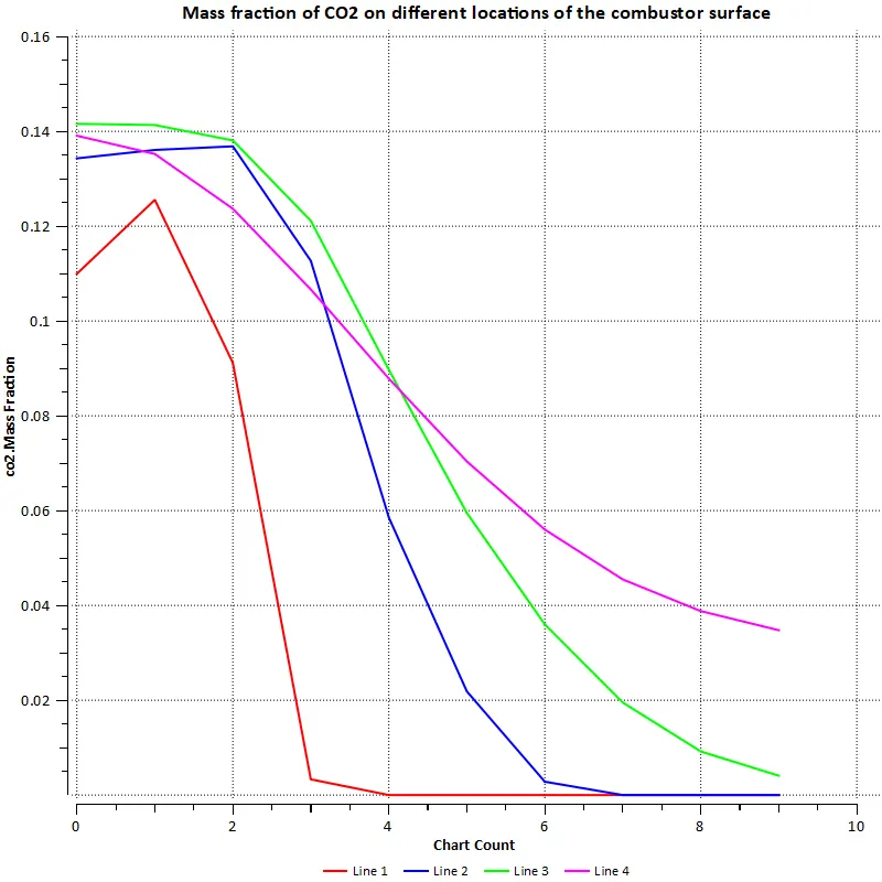
CO2 line plot:
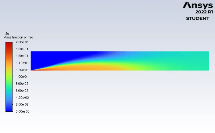
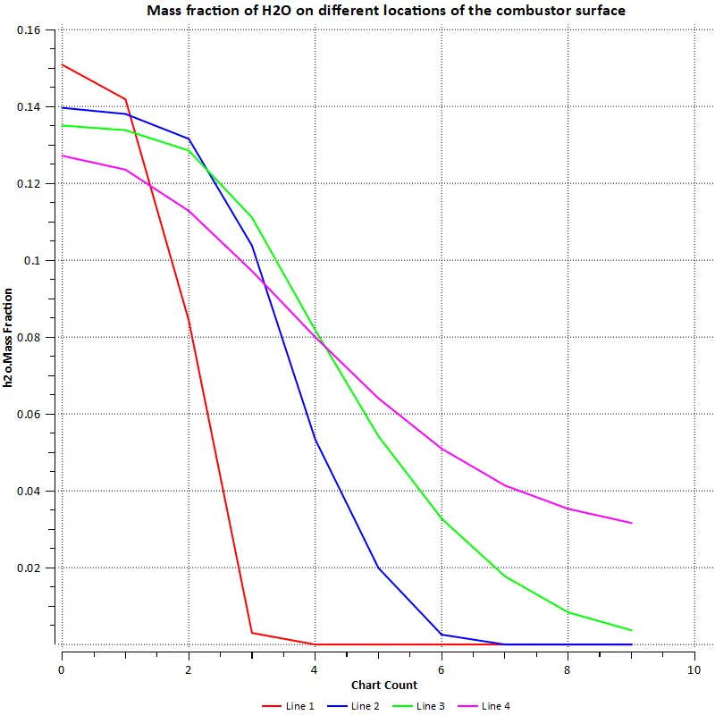
H2O contour:
H2O line plot
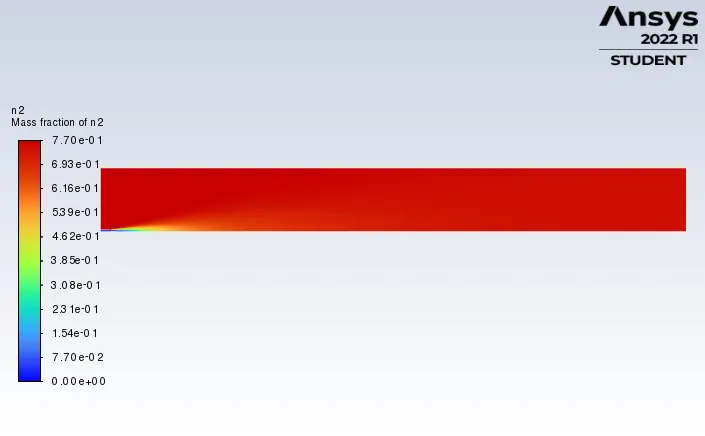
N2 contour:
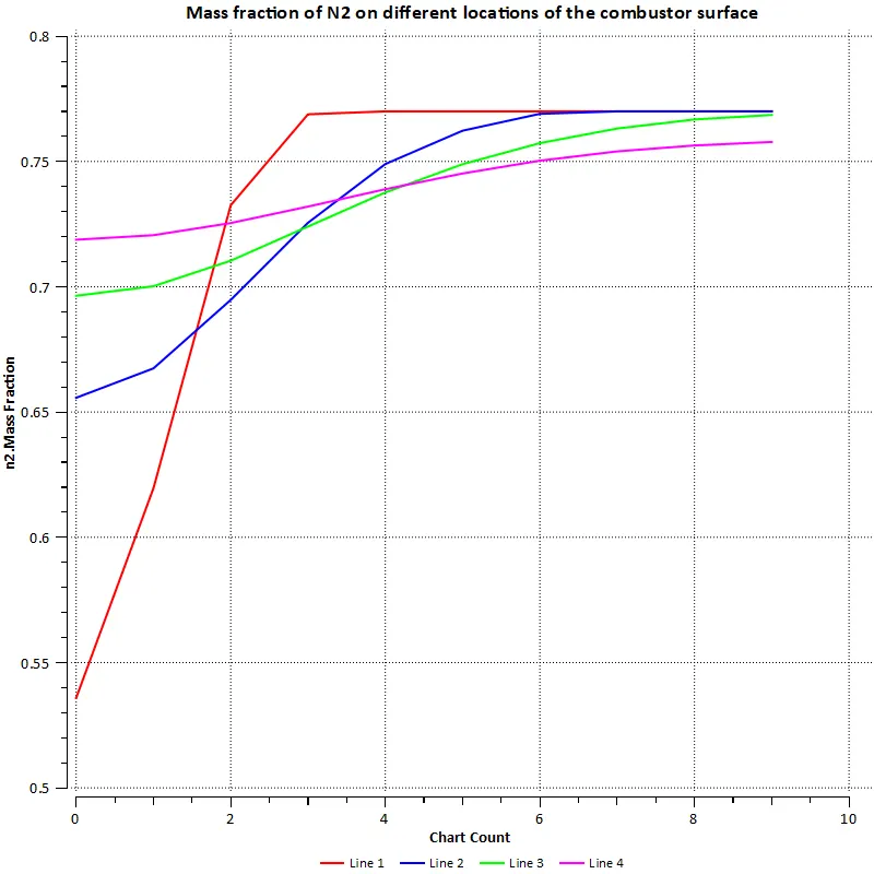
N2 line plot:
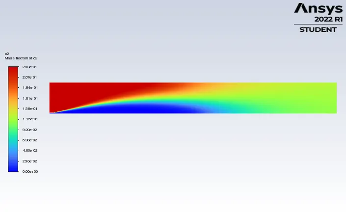
O2 contour:
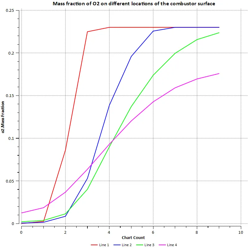
O2 line plot:
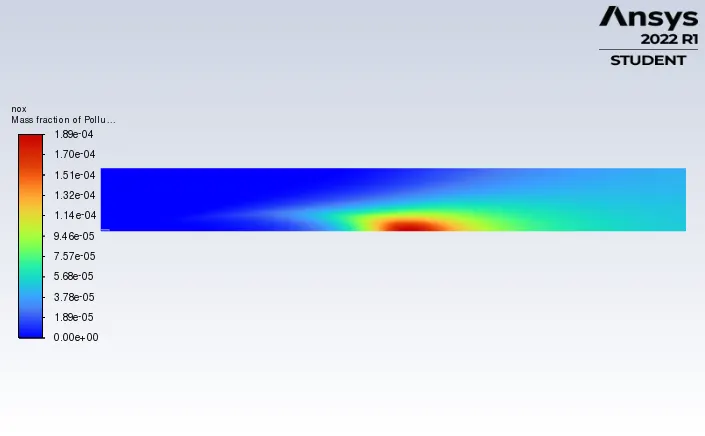
Pollutant NOx contour:
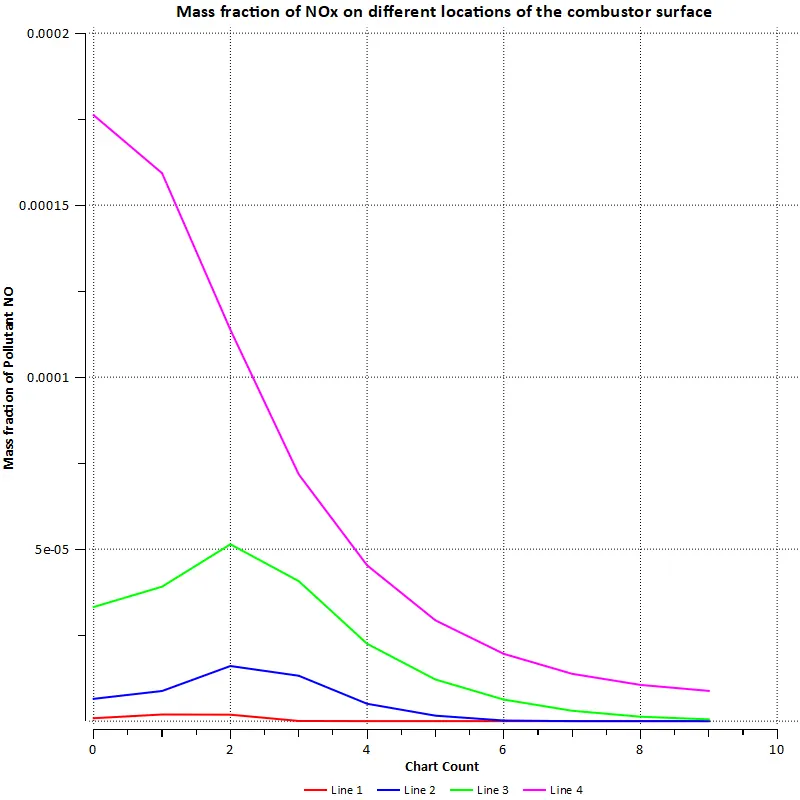
Pollutant NOx line plot:
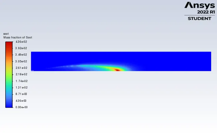
SOOT contour:
SOOT line plot:
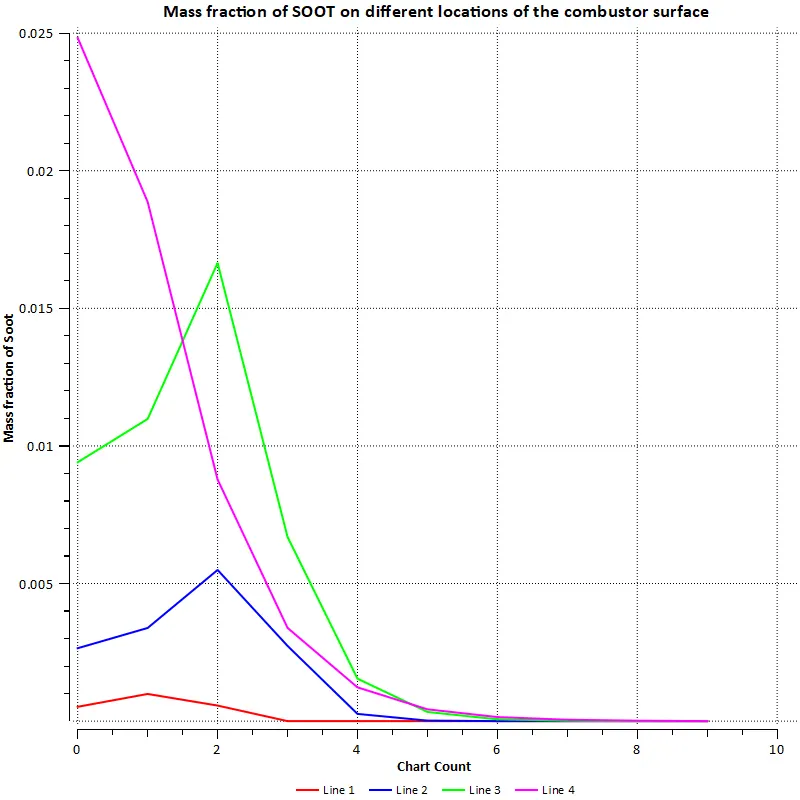
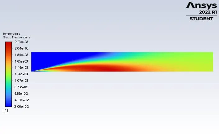
Case 4: 30% addition of water in the fuel
Temperature contour:
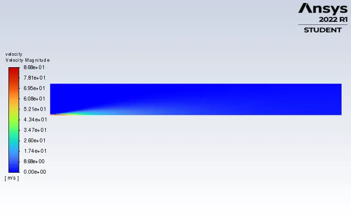
Velocity contour:
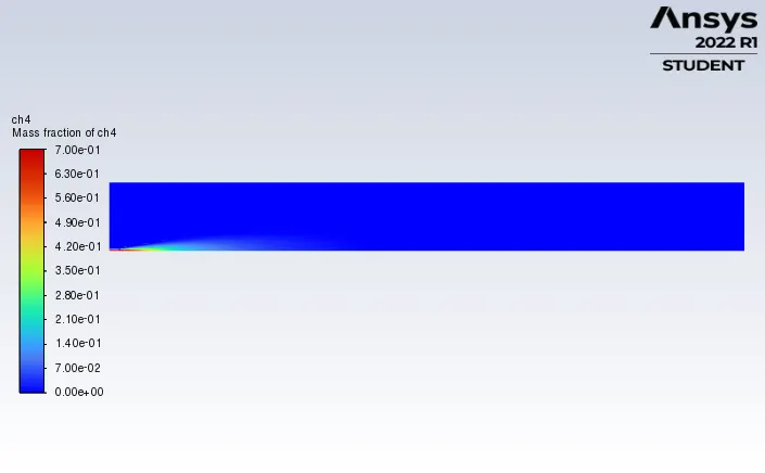
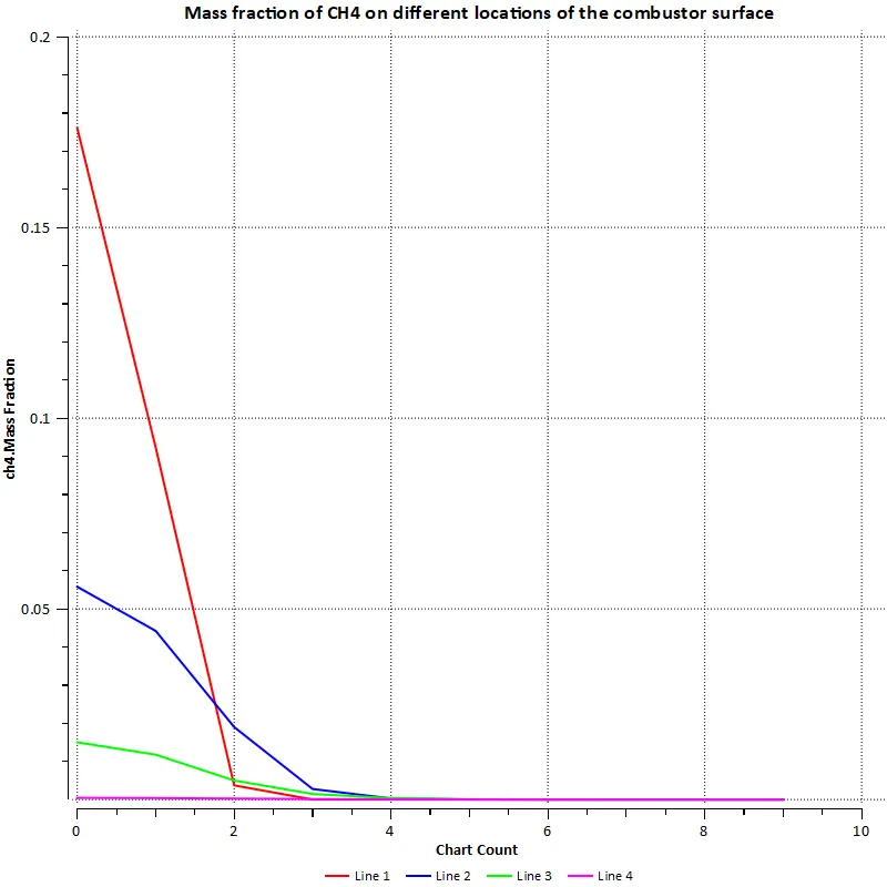
CH4 contour:
CH4 line plot:
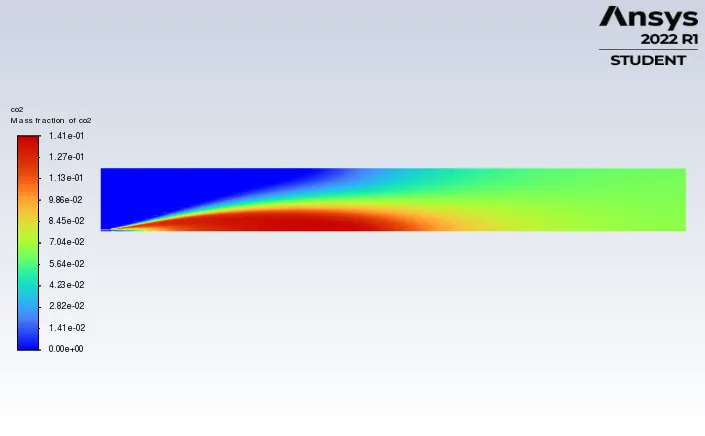
CO2 contour:
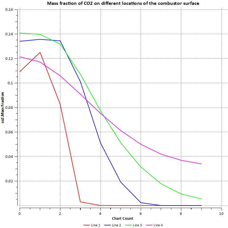
CO2 line plot:
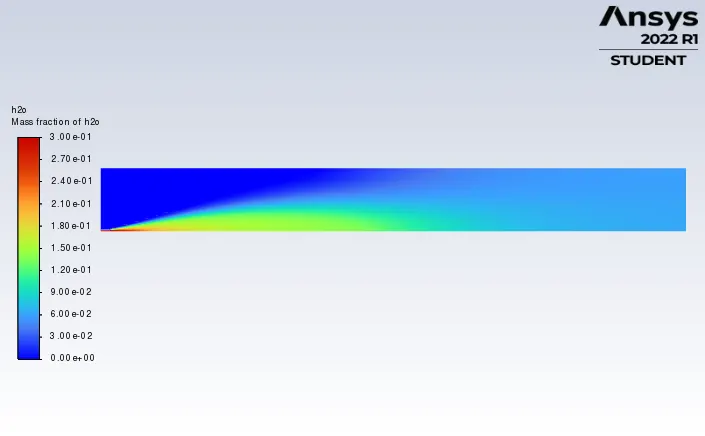
H2O contour:
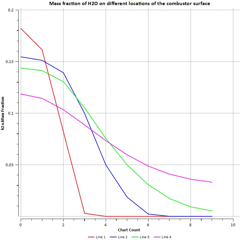
H2O line plot
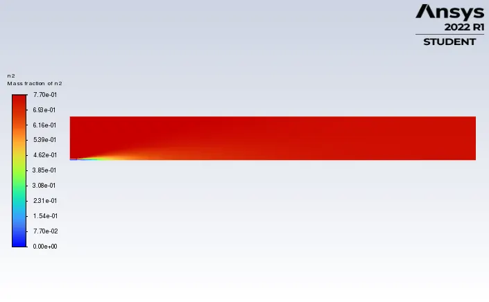
N2 contour:
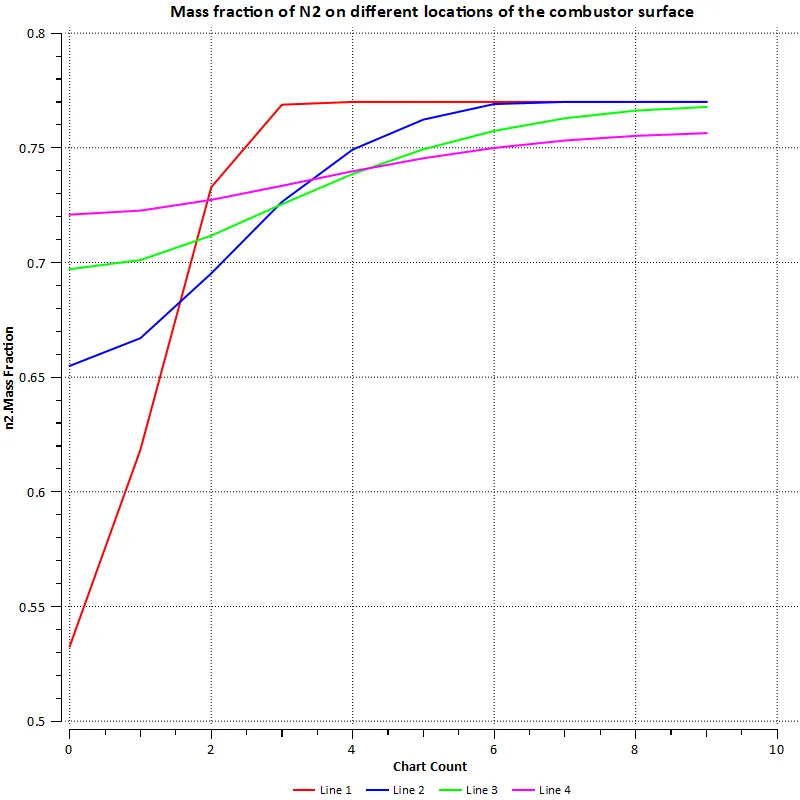
N2 line plot:
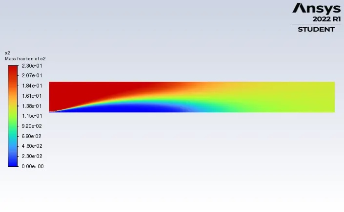
O2 contour:
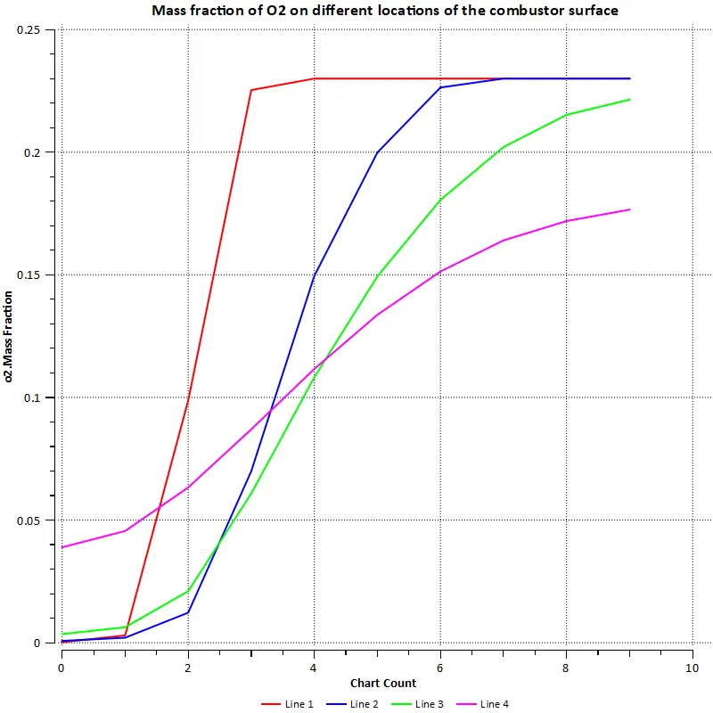
O2 line plot:
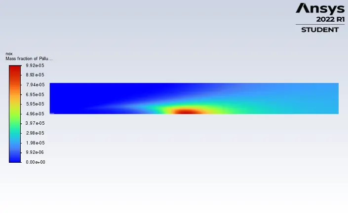
Pollutant NOx contour:
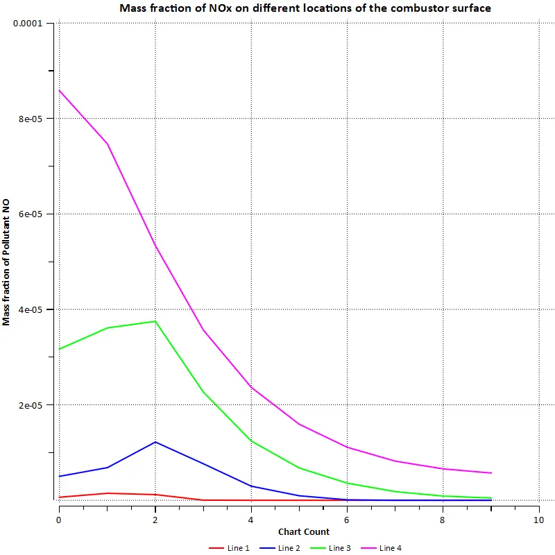
Pollutant NOx line plot:
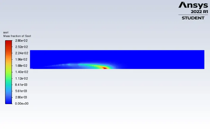
SOOT contour:
SOOT line plot:
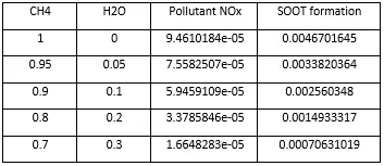
Comparison table:
Conclusion:
From the result obtained, we can conclude that
- Temperature decreases when we add the water with the fuel.
- Only a very slight decrease has been observed in the mass fraction of CO2 and no changes has been observed in the mass fraction of N2 & O2 when we add the water with the fuel.
- Toxic pollutant NOx and SOOT formation decreases when we add the water with the fuel which helps to reduce those toxic pollutants affecting the environment.