Week 10 - Simulating Combustion of Natural Gas.
Aim –
To simulate the combustion of natural gas to calculate the mass fraction and by adding the water in the fuel to observe the effects to avoid harmful effects on environment and human.
Objective –
Perform a combustion simulation on the combustor model and plot the variation of the mass fraction of the different species.
Add the water content in the fuel from 5% to 30% by mole and observe the effect of it on the results.
Introduction –
Natural gas, colourless highly flammable gaseous hydrocarbon consisting primarily of methane and ethane. Natural gas is one of the major combustion fuels used throughout the globe. Natural gas combustion is an exothermic chemical reaction in which natural gas and oxygen react, producing heat and several harmful chemical byproducts. To study combustion of natural gas CFD is used, by simulating combustion mixing of fuel and air, temperature rise, flame propagation, byproduct properties etc. can be predicted. In this study we will simulate natural gas combustion and find byproduct fractions with effect of mixture of water and fuel as inlet, on soot formation.
Theory –
The constant increase of world energy consumption, that represents a crucial challenge for researchers and scientists. Mostly, fossil fuel under goes some type of combustion and produce energy and byproducts. Obnoxity of emission is a main concern today because is it raising the global average temperature. NOx is one of the most dangerous byproducts, to limit it, water can be mixed during the combustion of natural gas. In this study we will study the effect of water quantity at inlet, on mass fraction of NOx and soot formation.
A combustion is the Exothermic chemical reaction of a fuel with an oxidant to form the product. Basically, there are two type combustion one is flame mode in which the thin zone of intense chemical reaction called 'flame' exist and another one is ‘non-flame’ mode in which volumetric combustion process is exited. The combustion simulation is performed to get the predictions of:
- Flow fields and mixing characteristics
- Temperature fields
- Species Concentrations
- Particulates and pollutants.
The application of combustion modelling is applying for various kind of reacting flows such as furnaces, boilers, Process heaters, Gas turbines, automobiles and Rocket engines. Modelling of combustion reaction in a software is difficult and need to take care for species which are taking part in reaction and its products. The combustion CFD model comprises of chemical kinetics and similarly achieving reacting flow mixture environment. Considering chemical kinetics, it is also important to have properly defined physical model with simulation to get the maximum out of process. Computational fluid dynamics of combustion model should be capable of enough to provide information related to species concentration, their volumetric generation or diffusion rate and changes in the system parameters like enthalpy, temperature and mixture density. The similar model should be good enough to solve the general transport equations for fluid flows and heat transfer as well as additional equations of combustion chemistry and chemical kinetics incorporated as per simulation environment details.
Chemical kinetics is part of combustion phenomenon, which is the study of entire reaction mechanism subject to different operating conditions. The whole reaction mechanism is the overall reaction of fuel and air with the elementary reaction. The elementary reaction is consisting of intermediate reaction cause generation of intermediate species, and the species react with fuel and air will cause the elementary reaction. This intermediate reaction caused due to breakup of chain reaction of fuel and air. The chemical kinetics is important as it provide when combustion process is going to start i.e., time period of ignition delay, rate of work done and used to determine emission from the chemical reactions. The elementary reactions in the case any combustion phenomena are mostly of three types which are bimolecular reactions, unimolecular reactions and thermolecular reactions. In bimolecular reaction the reactants produce the product and same product can be undergoing to produce the reactant. This reaction is most common in combustion. In unimolecular reaction there are two types one is isomerization in which transformation of composition is occurred and another case is decomposition in which breakdown of composition is occurred.
Combustion Model –
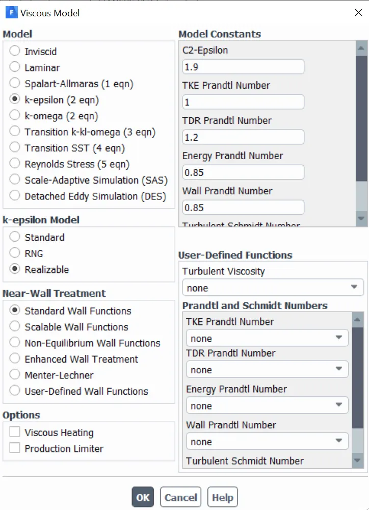
In combustion process most of the fuel are fast burning and the overall rate of reaction is controlled by mixing caused due to turbulence. In non-premixed flames, turbulent cause the fuel and oxidizer to mix and convert them into reaction zones where it burns as quickly as possible. Similarly, turbulence also mixes the cold reactants and hot products into the reaction zones, where reaction happen rapidly. Hence for pre-mixed combustion eddy dissipation model can be used to create the reaction into chamber. This model is only applicable for turbulent flows only. It assumes the reaction is fast relative to the transport processes in the flow. The reaction rate is proportional to turbulent mixing time defined by kinetic energy (k) and it dissipation rate epsilon (e) and hence we’ll be using the k-epsilon model for this analysis.
NOx and Soot formation –
The formation of NOx and soot are due the incomplete combustion or due to excess amount of fuel inside the chamber. The formation of soot is also depending on the temperature of reaction. If the temperature of reaction is not high enough to produce the product of reaction, then formation of soot is occurred. The NOx emission can be formed through series of mechanism during both the premixed and diffusion burning. As in methane-air-2step mixture for the baseline setup the fuel present in higher quantity which rises to creation of NOx and soot in the chamber.
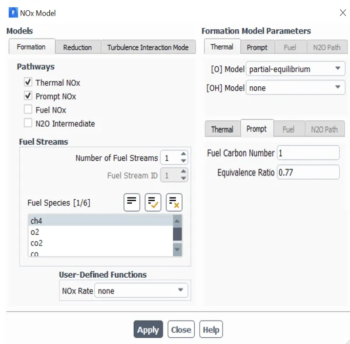
To capture the effect of NOx and soot in the burner the FLUENT have NOx and Soot model which incorporate with eddy dissipation model of species transport. For determining the NOx FLUENT has different pathways in which NOx formation is occur during the combustion process. The pathways are Thermal NOx, Prompt NOx, Fuel NOx and NO2 intermediate. In case of Thermal NOx is depend upon highly temperature dependent chemical reactions. The Prompt NOx formation is proportional to number of carbon atoms present per unit volume and independent of parent hydrocarbon identity.
The creation of Prompt NOx is most prevalent in rich kind of flames reactions. The main source of Prompt NOx is from the fuel fragmentation in hydrocarbon flames and the major contribution is CH and CH2. Hence it is important to check the Prompt NOx pathways to determine the generation of NOx in combustion reaction.
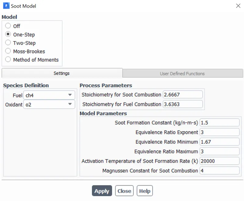
Beside of Thermal NOx and Prompt NOx the fuel NOx also contributes in creation of major NOx. The nitrogen-containing organic compounds present in the liquid or solid fossil fuel which contribute for the formation of NOx during combustion process. Similar to NOx the soot formation is also incorporated in the simulation by one-step method.
Geometry -
For this analysis initially we have a 3D model of the system in which the combustion takes place, in order to get the required geometry for our analysis, we'll perform some operations on this geometry and get the required geometry. Given below are the steps that'll we followed to extract the required geometry from the given 3D model.
3D Model -
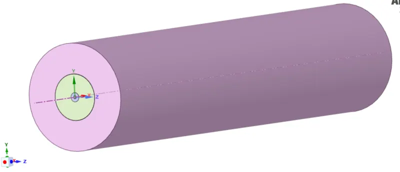
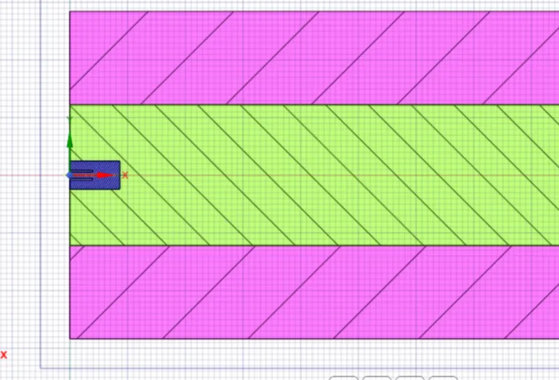
From above two geometries we can see the three different solid insides of each other. As the solution point of view the fuel is entering from the opening diameter of 3.3mm and rest is the air entering in chamber.
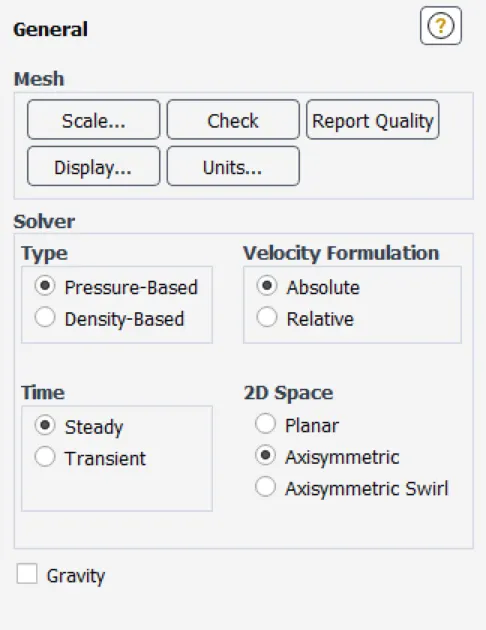
The simulation approach we'll use for the problem is 2D Axi-symmetry steady state turbulent model with species transport equation. The use of 2D Axi-symmetric model reduce the work load on the computational source and will reduce the time required for simulation.
Spliting the model -
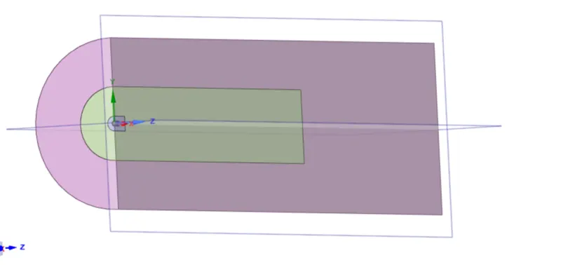
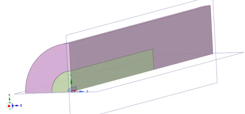
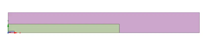
These are the surfaces we need for our analysis and hence we'll copy these surfaces and make a new design file, which will be the geometry we required.

Required Geometry -

Mesh -
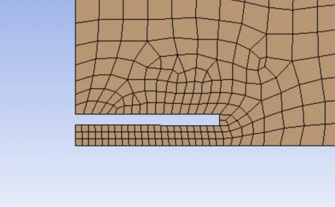
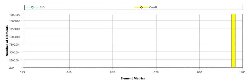
Since the geometry is simple, high-quality quad cells are used. The mesh is fine with an element size of 2mm and 17170 cells.

Named Selection -
Fuel Inlet -

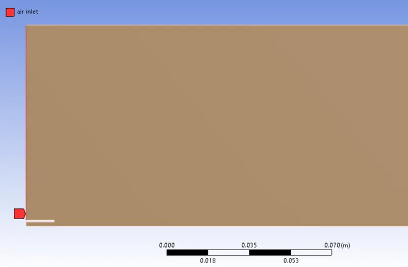
Air Inlet -
Axis -

Wall -

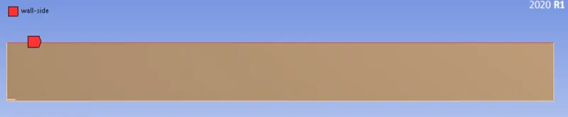
Wall-side -
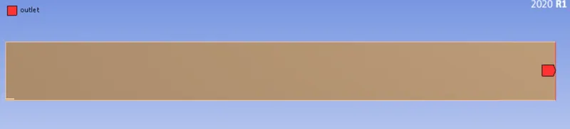
Outlet -
Element Quality -
Setup -
General setting -
Viscous Model -
Species model was enabled. Species transport was selected, because it solves conservation equation for all species, which predicts the transport and their production in the combustion zone. In fluid phase volumetric reaction is considered always, so it was selected. Inlet diffusion and diffusion energy source was selected in this setup combustion chamber does not have any ignition source, combustion is arising due to diffusion turbulence of fuel and air.
Methane-air-2step selected as mixture material which allows water addition. We proceeded with eddy dissipation model due to its robustness and it takes less time to solve model compare to other models.
Species Model -
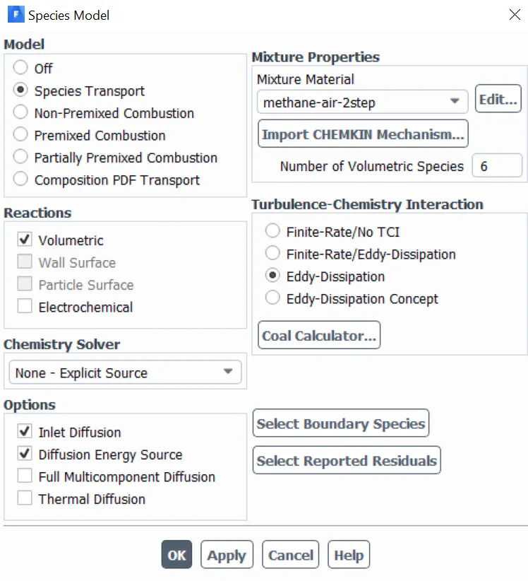
Similar to species model setup, NOx and soot model has to be done accordingly. As discussed earlier the NOx can be produce due to high temperature and rich fuel mixture, hence all the pathways which can track the generation of NOx are activated for the simulation. Similarly, the soot model is also activated in which one-step soot model is used for the tracking of soot generation during the combustion process.
NOx Model -
Soot Model -
Boundary Conditions -
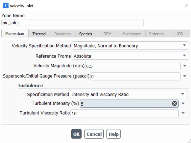
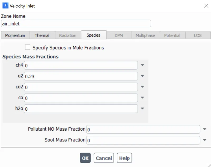
Air Inlet = 0.5m/s
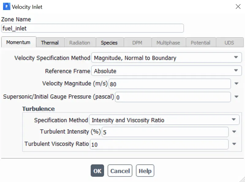
Fuel Inlet = 80m/s
Reaction used in analysis is :-
`CH_4 + 2(0_2 + 3.76N_2) implies CO_2 + 2H_2O +7.52N_2`
There for total mole fraction of air = 9.52 ( 2 moles of O2 + 7.52 moles of N2)
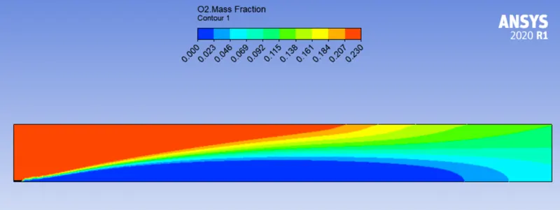
Mole fraction of O2 = moles of O2/total moles = 2/9.52 = 0.23
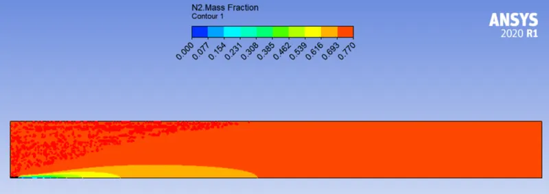
Mole fraction of N2 = moles of N2/total moles = 7.52/9.52 = 0.77
Mole fraction of CH4 = 1
Mole fraction or mass fraction can be given to specify species.
Air Inlet -
Fuel Inlet -
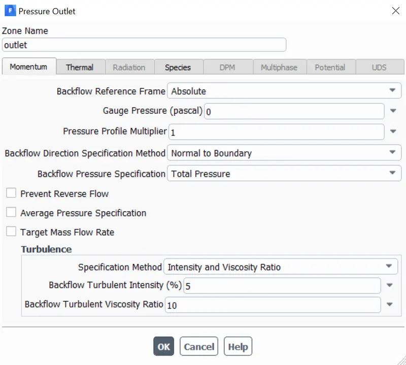
Outlet -
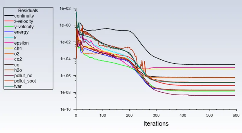
Now we're done setting up the problem and hence we can now start iterations for the calculation.
Iterations - 600
Results -
Residual -
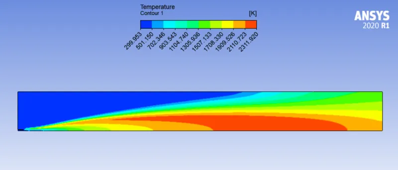
Temperature Contour -
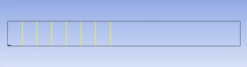
Line probe locations for mass fraction plot of different species -
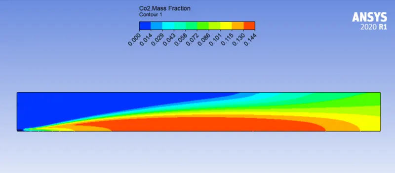
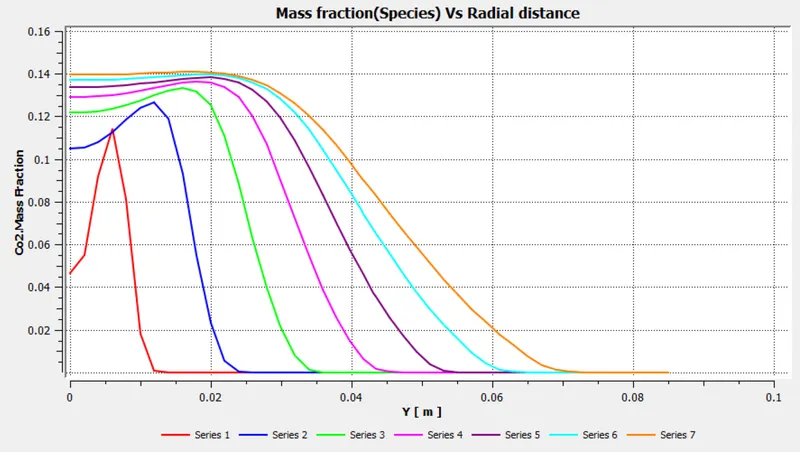
CO2 mass fraction contour and plot -
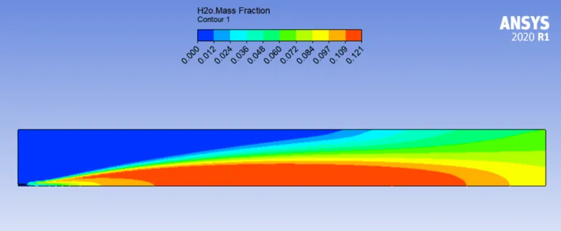
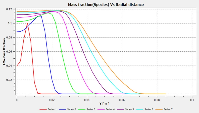
H2O mass fraction contour and plot -
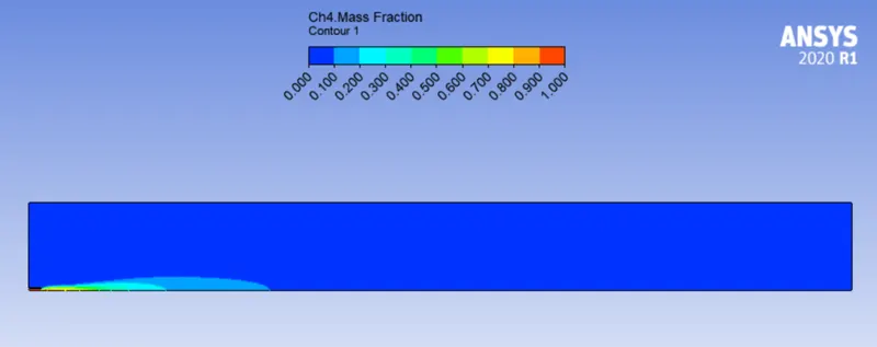
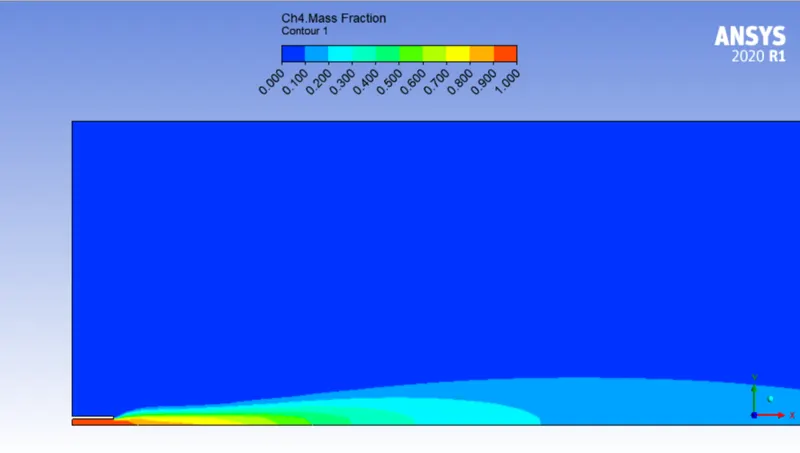
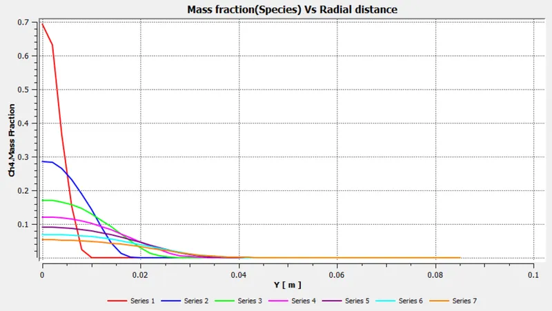
CH4 mass fraction contour and plot -
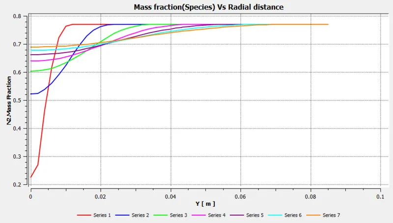
N2 mass fraction contour and plot -

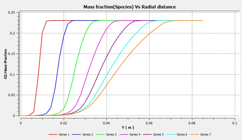
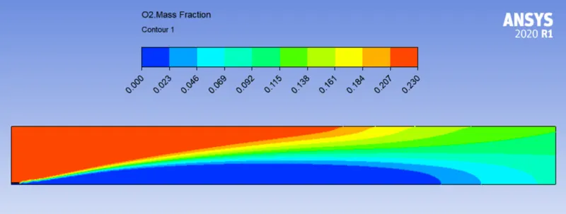
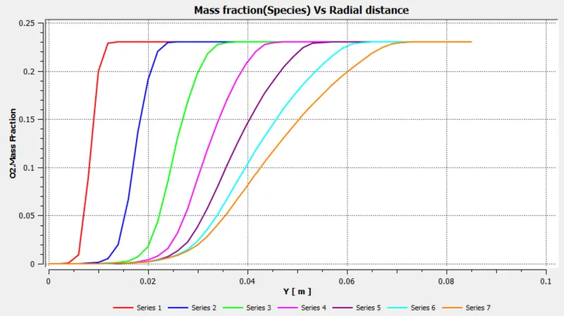
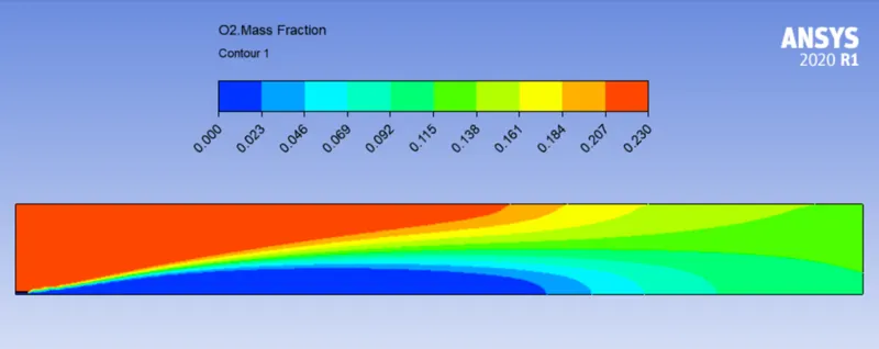
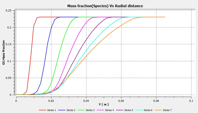
O2 mass fraction contour and plot -
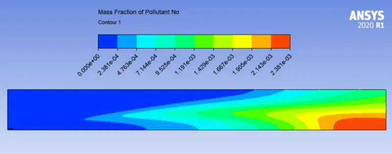
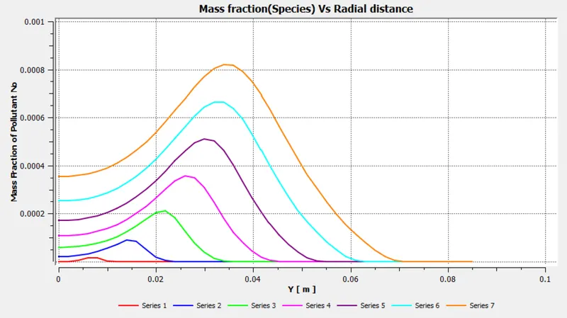
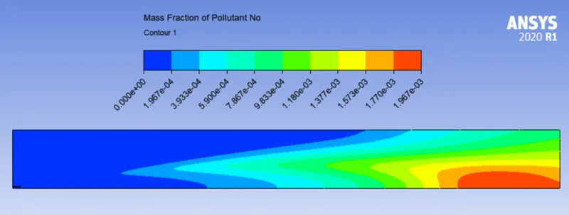
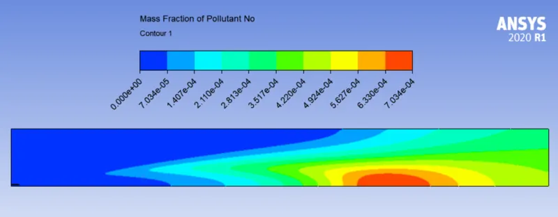
NOX mass fraction contour and plot -
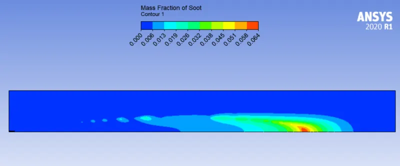
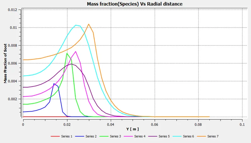
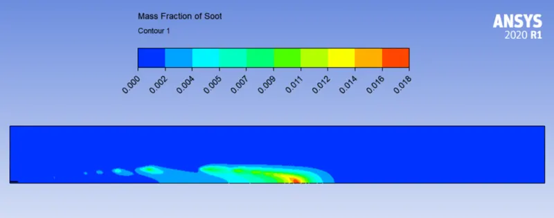
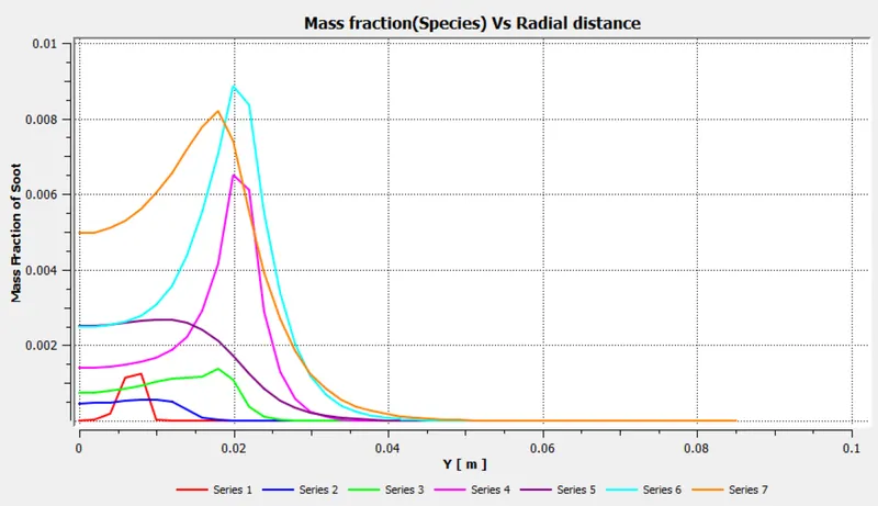
Soot mass fraction contour and plot -
PART 2 -
Adding water in the fuel by mole fraction (5% - 30% mole fraction) to see its effect on NOx and soot formation.
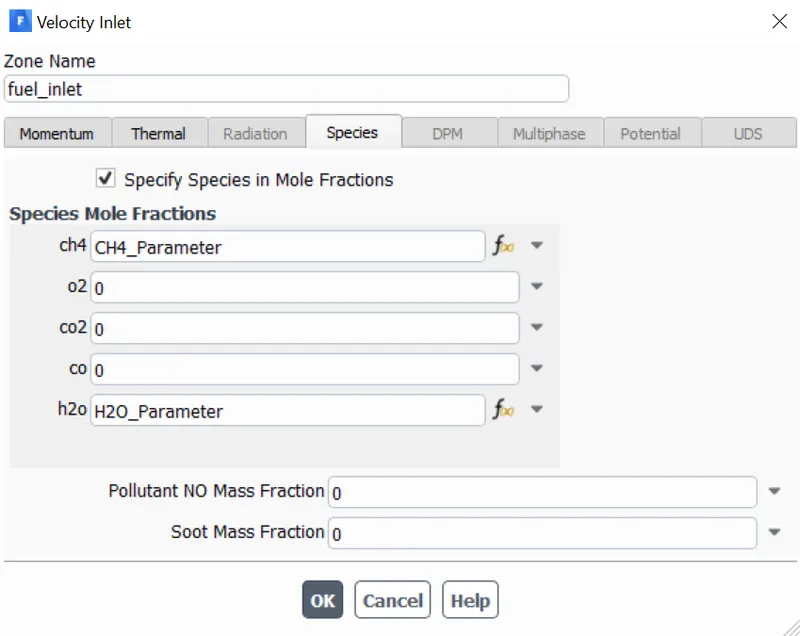
In order to reduce our time and effort, we can use the parameterization method in ANSYS Fluent to specify the mole percentage of CH4 and H2O as shown below.
Parameterization of mass fraction of CH4 and H2O -
Parameters tab -
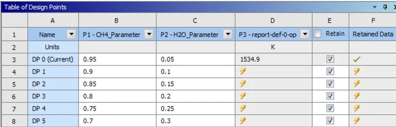
Let's update all the design points to get the result .
Parameter Result -
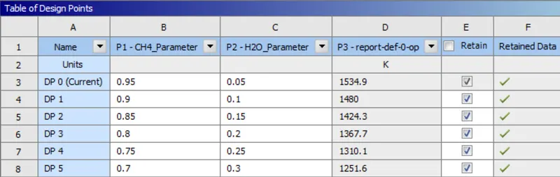
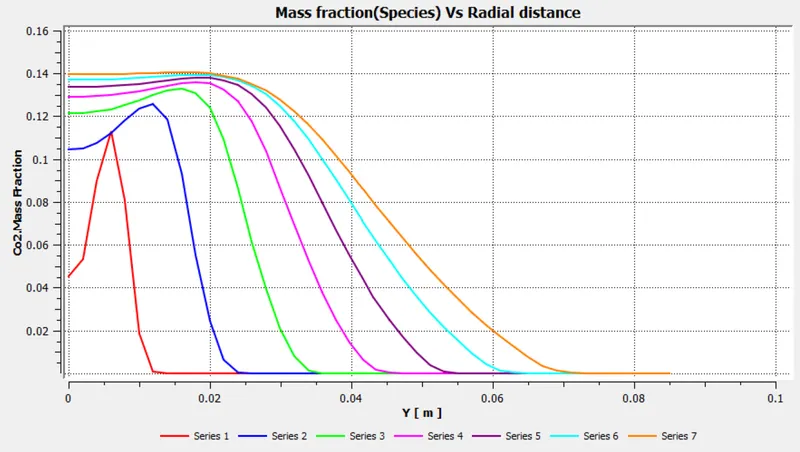
DP0 - CH4 - 95% , H2O - 5%
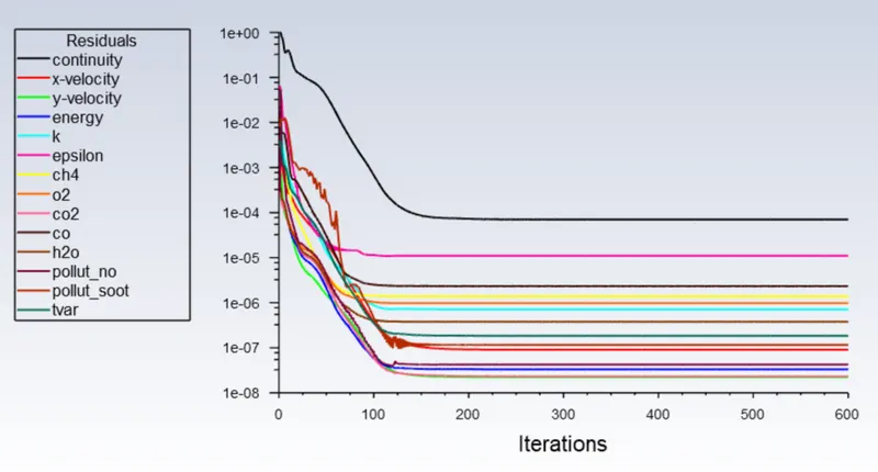
Residual -
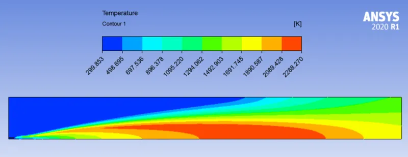
Temperature Contour -
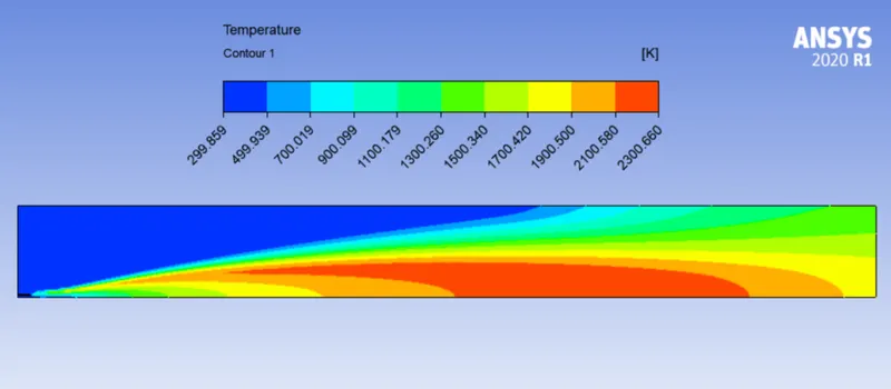
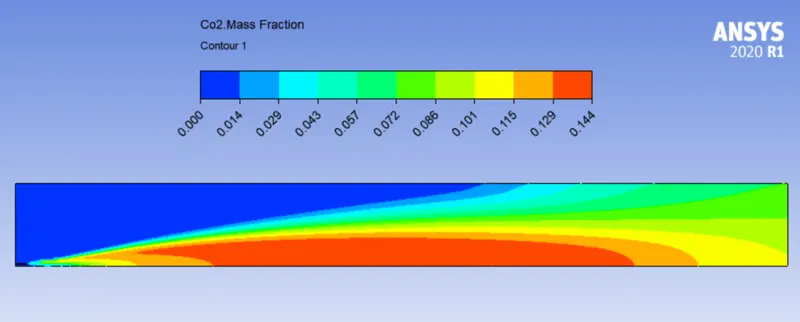
CO2 mass fraction contour and plot -
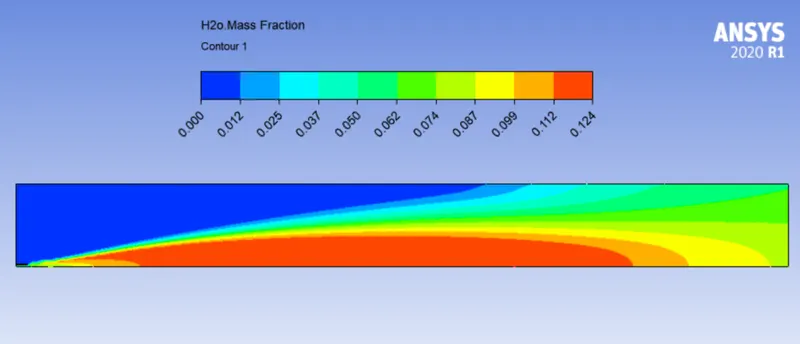
H2O mass fraction contour and plot -
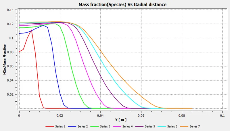
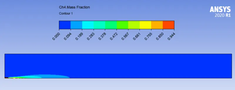
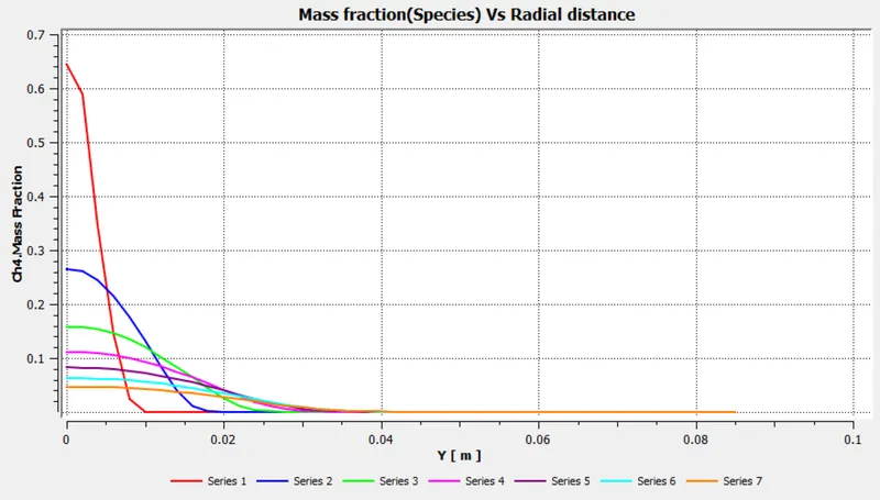
CH4 mass fraction contour and plot -
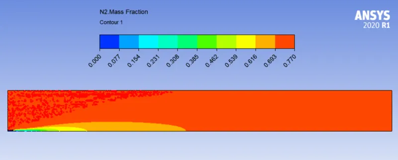
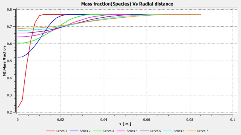
N2 mass fraction contour and plot -
O2 mass fraction contour and plot -
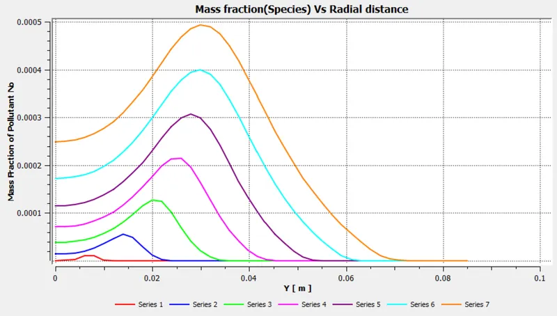
NOX mass fraction contour and plot -
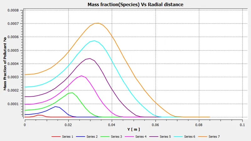
Soot mass fraction contour and plot -
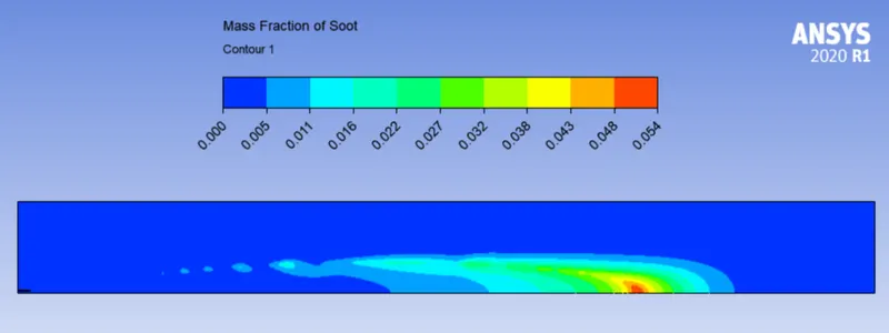
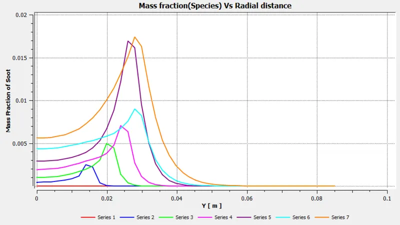
DP1 - CH4 - 90% , H2O - 10%
Residual -
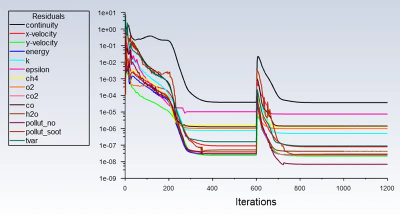
Temperature Contour -
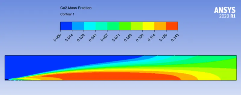
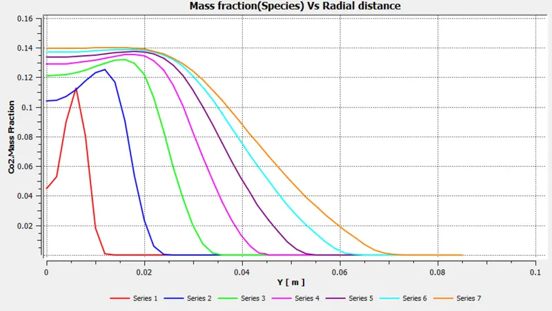
CO2 mass fraction contour and plot -
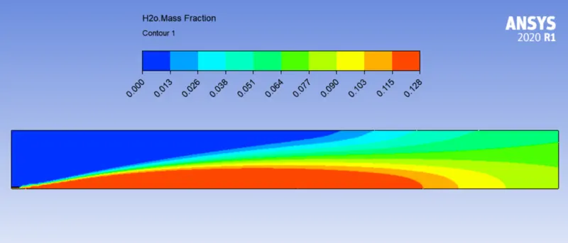
H2O mass fraction contour and plot -
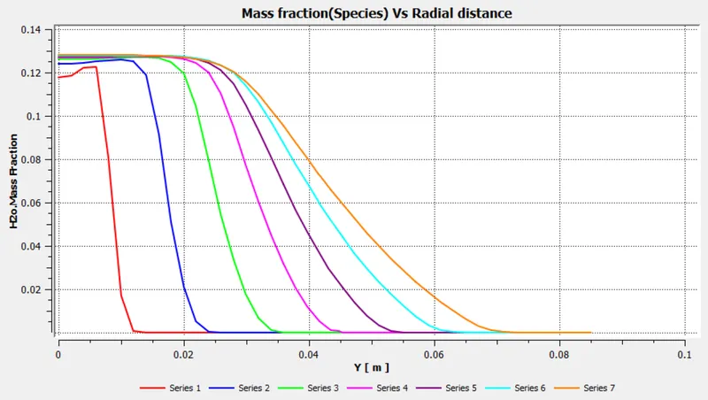
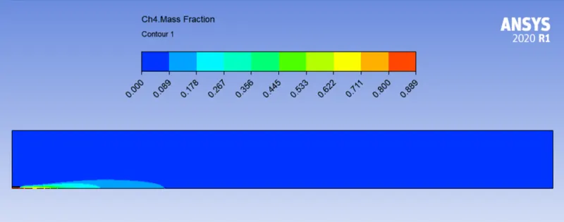
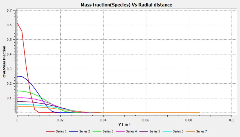
CH4 mass fraction contour and plot -
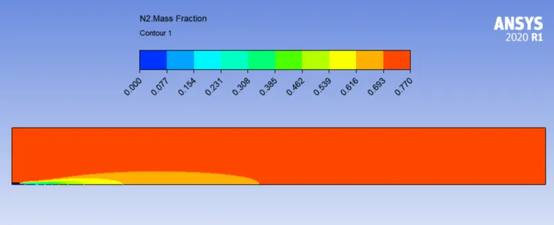
N2 mass fraction contour and plot -
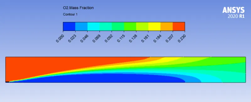
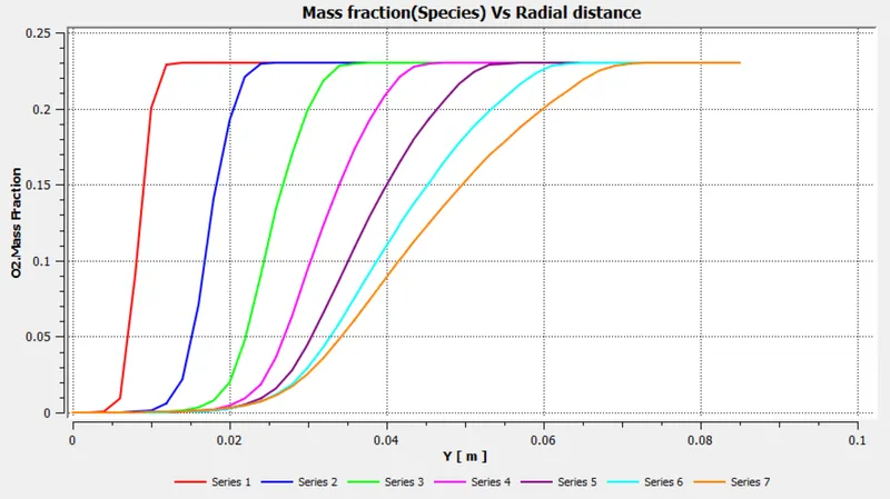
O2 mass fraction contour and plot -
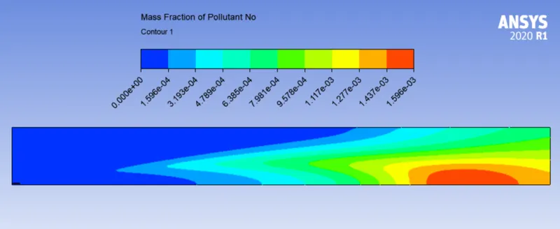
NOX mass fraction contour and plot -
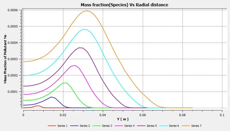
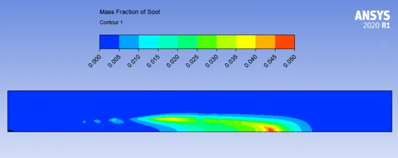
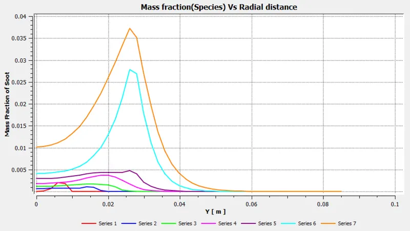
Soot mass fraction contour and plot -
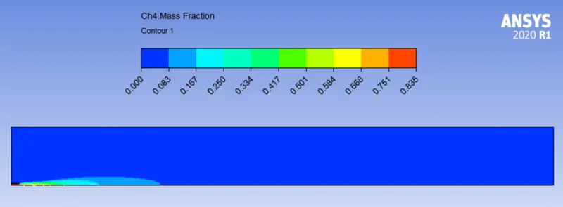
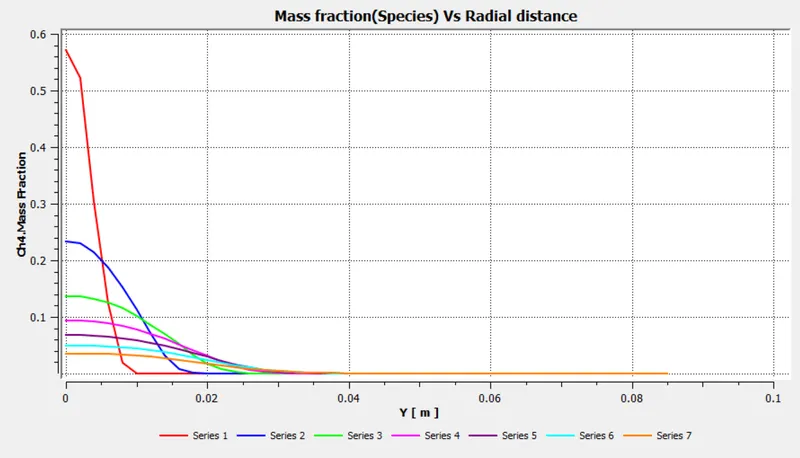
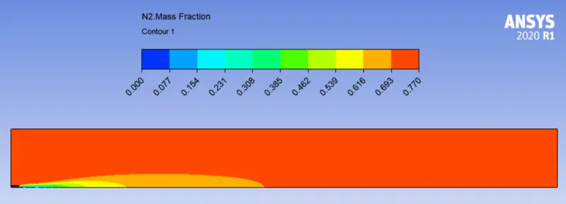
DP2 - CH4 - 85% , H2O - 15%
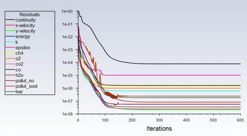
Residual -
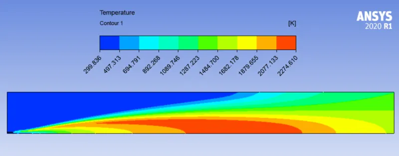
Temperature Contour -
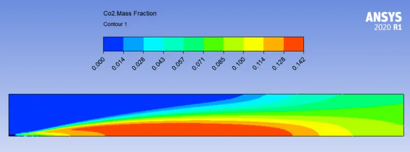
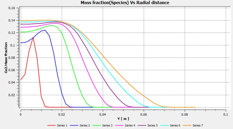
CO2 mass fraction contour and plot -
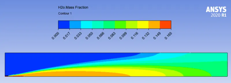
H2O mass fraction contour and plot -
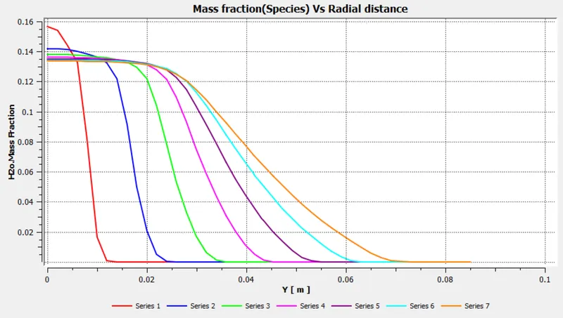
CH4 mass fraction contour and plot -
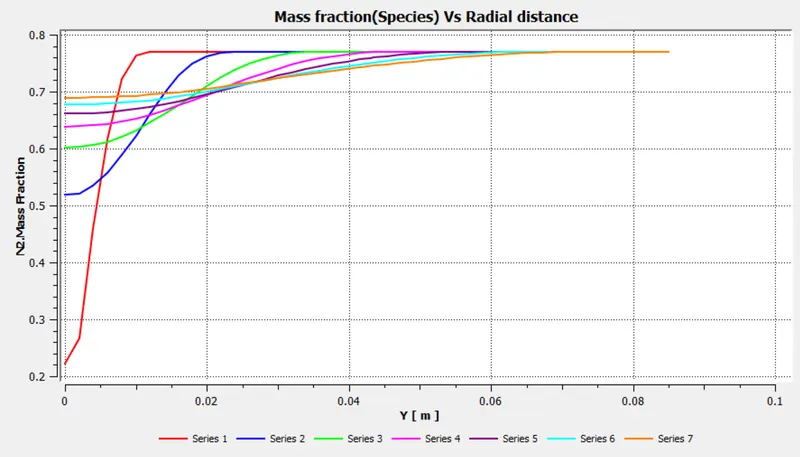
N2 mass fraction contour and plot -
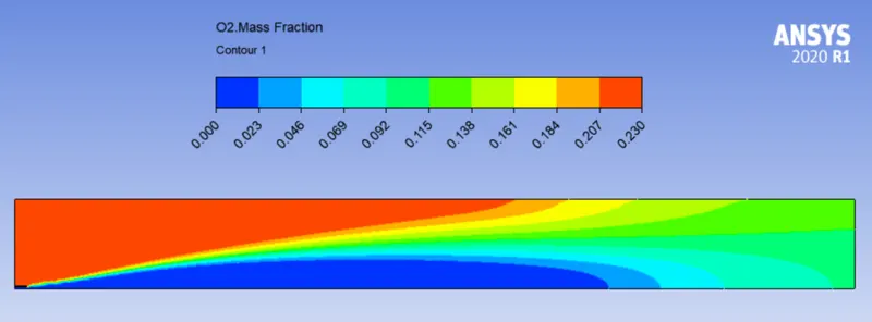
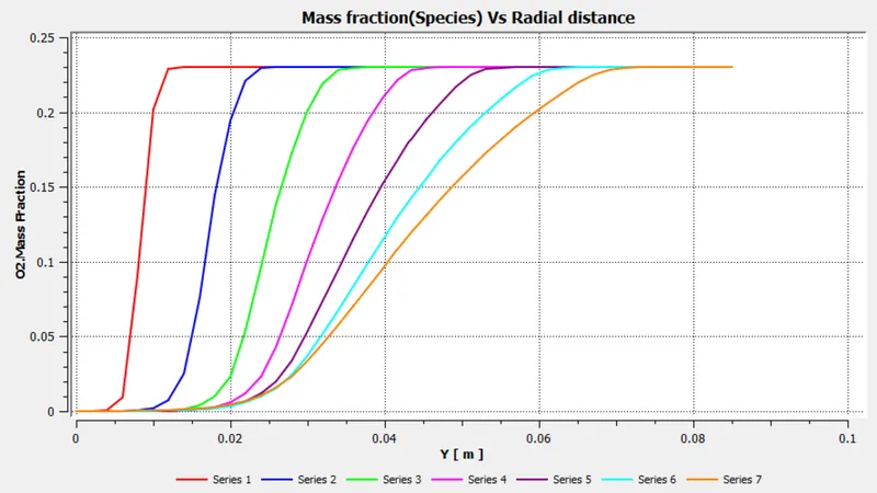
O2 mass fraction contour and plot -
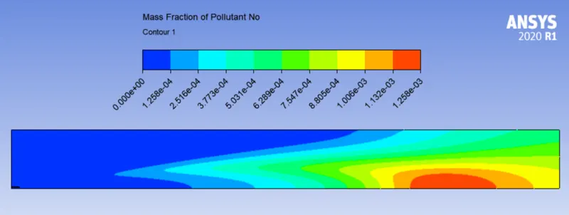
NOX mass fraction contour and plot -
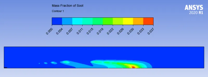
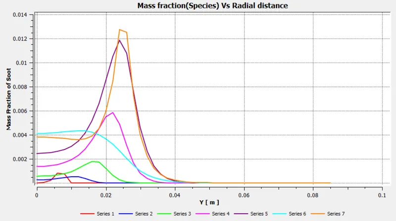
Soot mass fraction contour and plot -
DP3 - CH4 - 80% , H2O - 20%
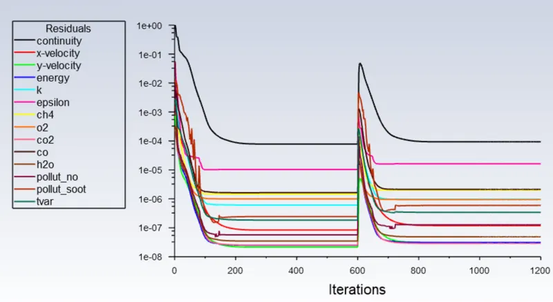
Residual -
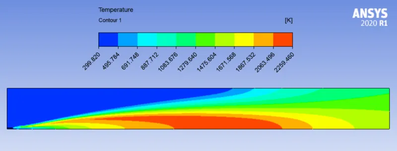
Temperature Contour -
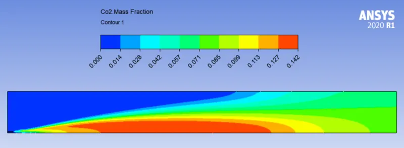
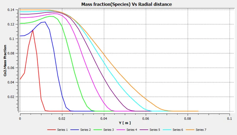
CO2 mass fraction contour and plot -
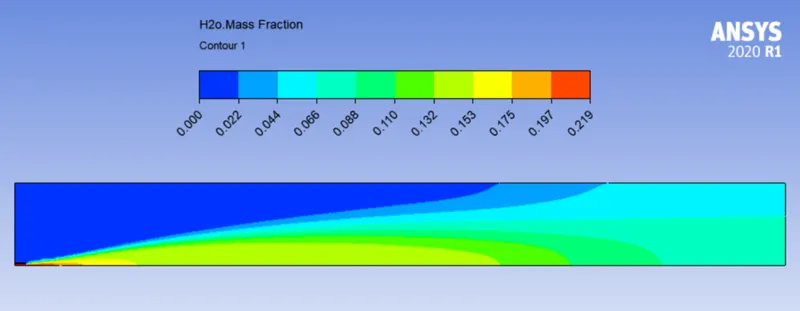
H2O mass fraction contour and plot -
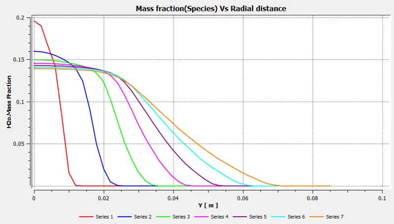
CH4 mass fraction contour and plot -
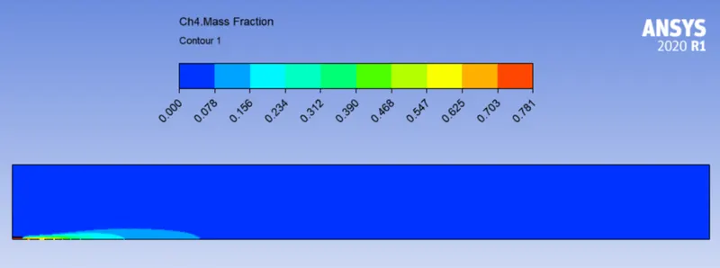
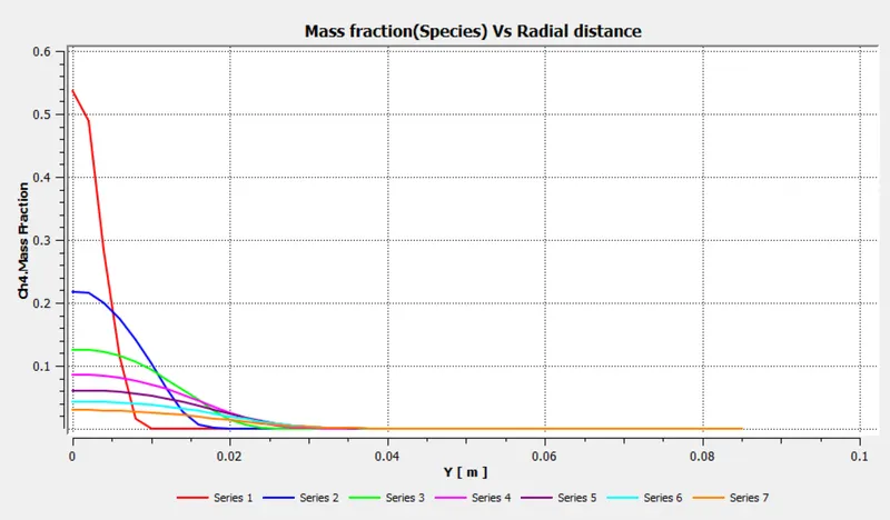
N2 mass fraction contour and plot -
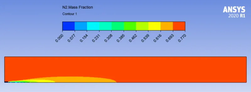
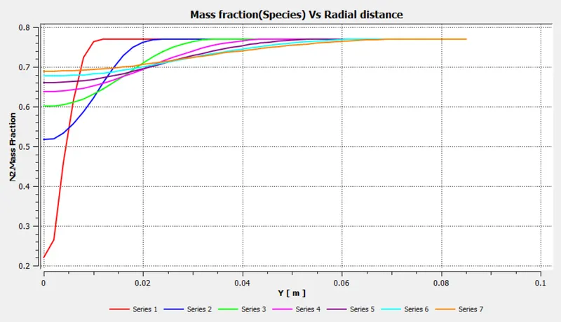
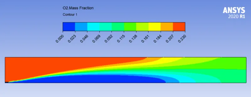
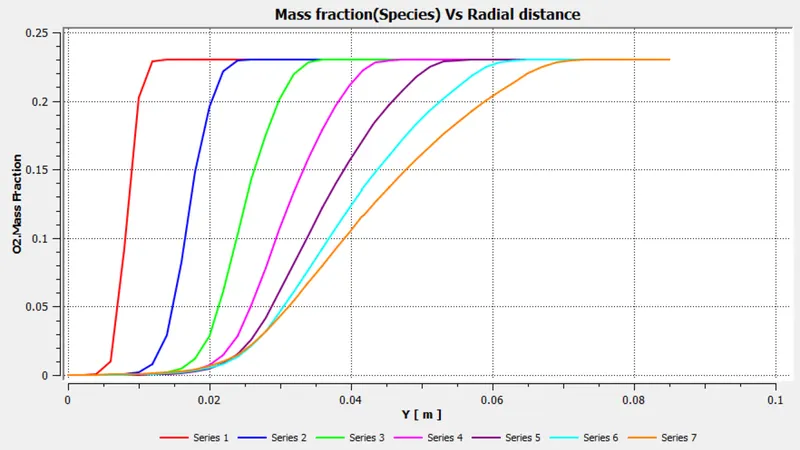
O2 mass fraction contour and plot -
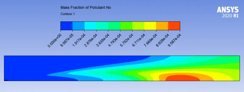
NOX mass fraction contour and plot -
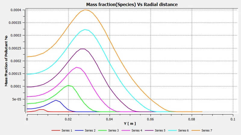
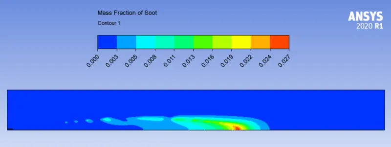
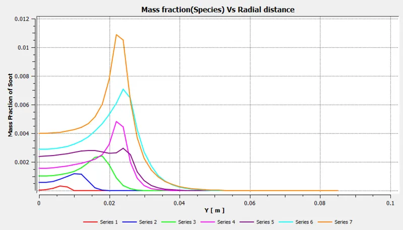
Soot mass fraction contour and plot -
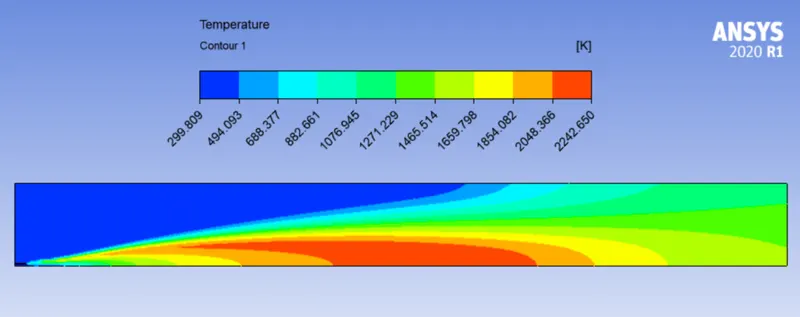
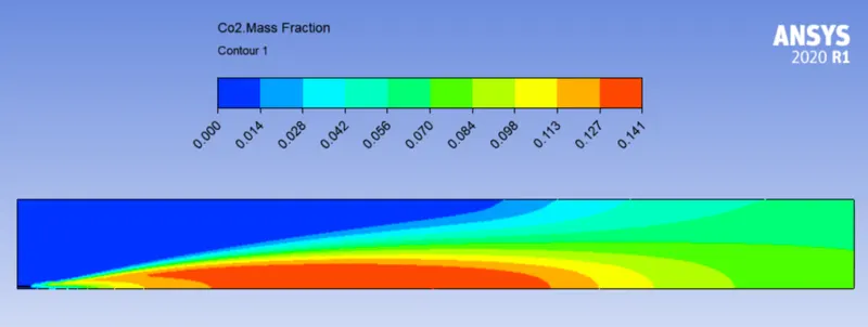
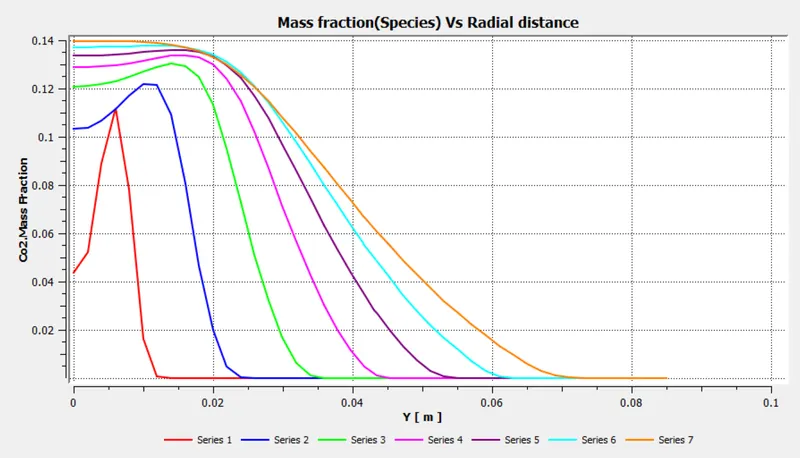
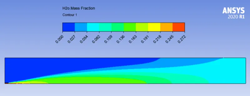
DP4 - CH4 - 75% , H2O - 25%
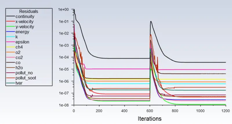
Residual -
Temperature Contour -
CO2 mass fraction contour and plot -
H2O mass fraction contour and plot -
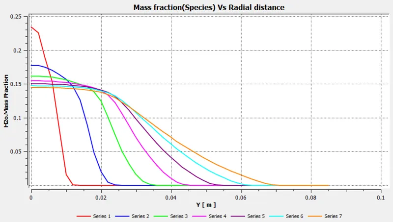
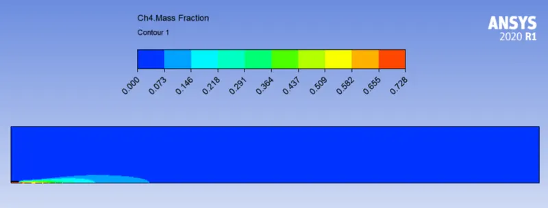
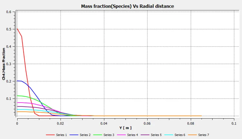
CH4 mass fraction contour and plot -
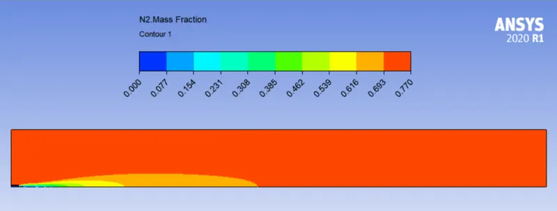
N2 mass fraction contour and plot -
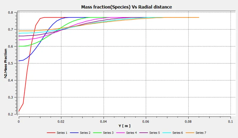
O2 mass fraction contour and plot -
NOX mass fraction contour and plot -
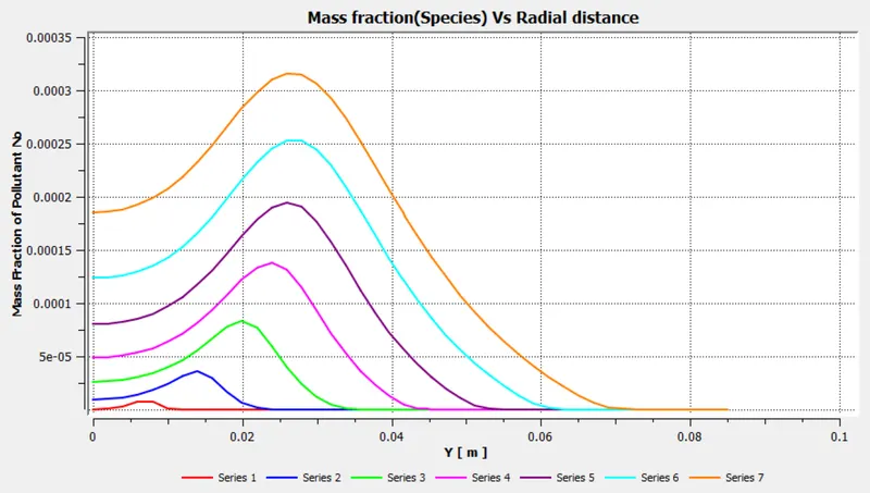
Soot mass fraction contour and plot -
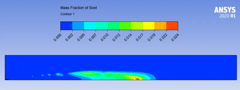
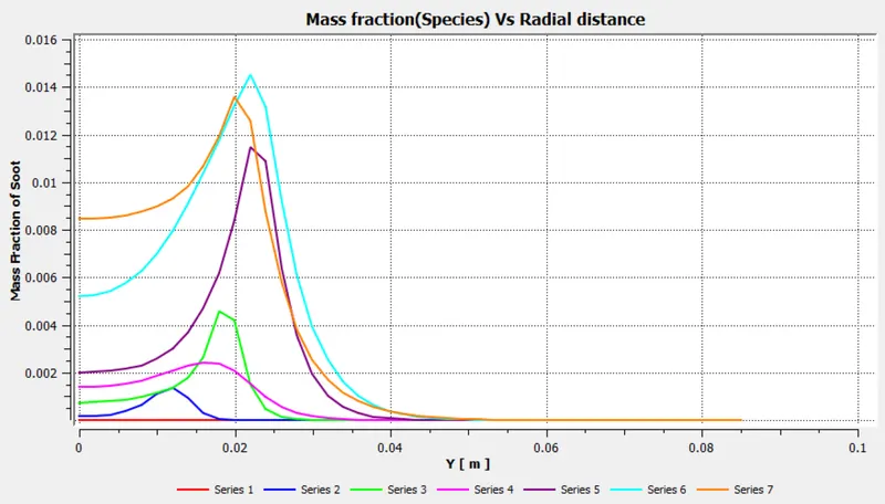
DP5 - CH4 - 70% , H2O - 30%
Residual -

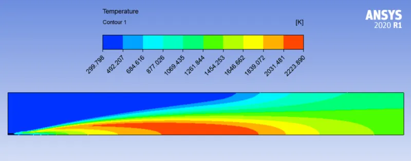
Temperature Contour -
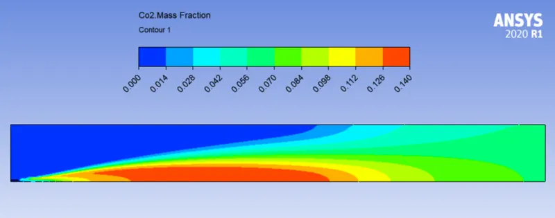
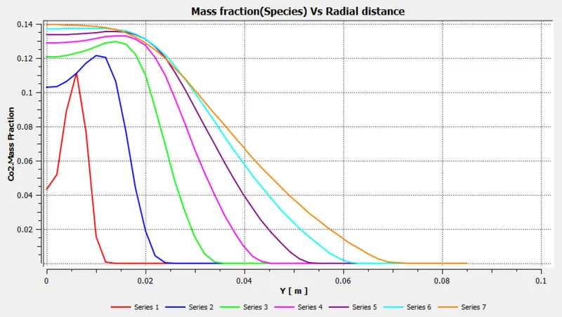
CO2 mass fraction contour and plot -
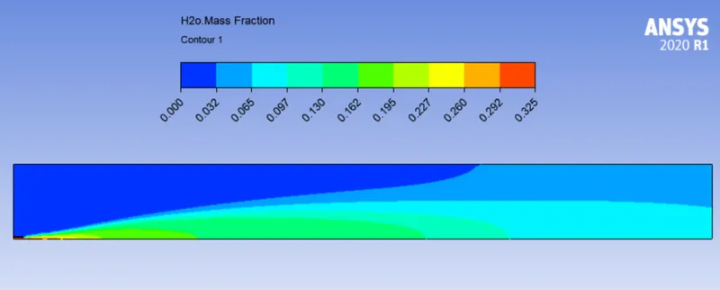
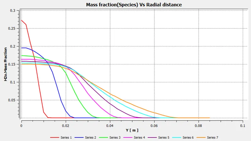
H2O mass fraction contour and plot -
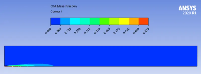
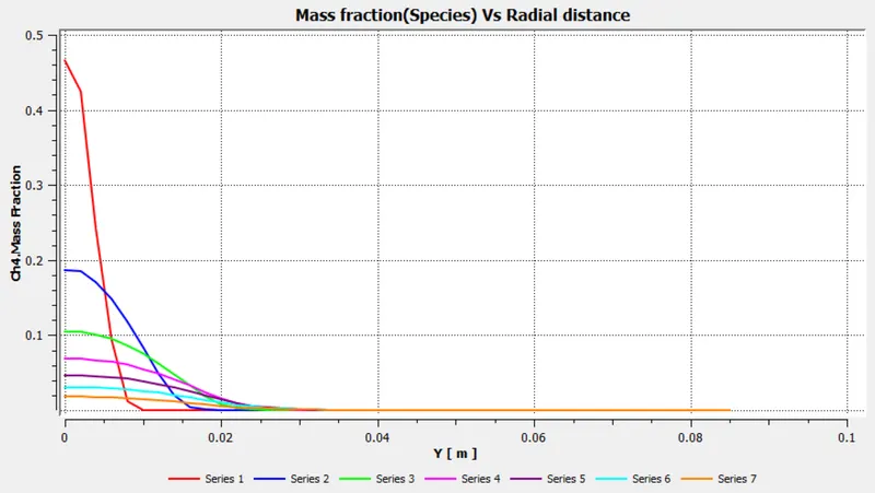
CH4 mass fraction contour and plot -
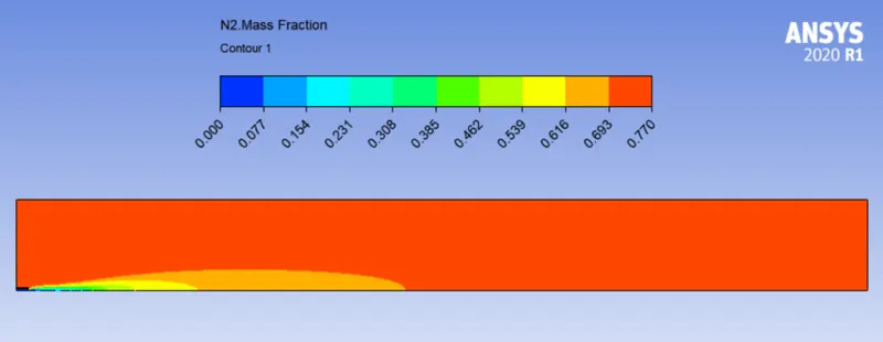
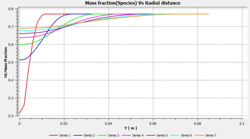
N2 mass fraction contour and plot -
O2 mass fraction contour and plot -
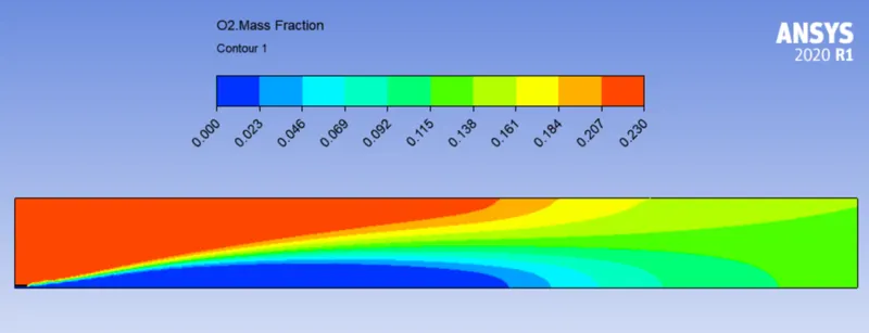
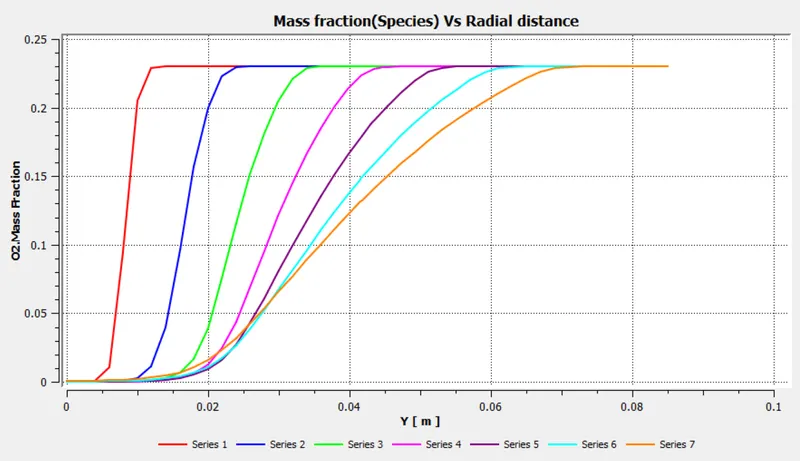
NOX mass fraction contour and plot -
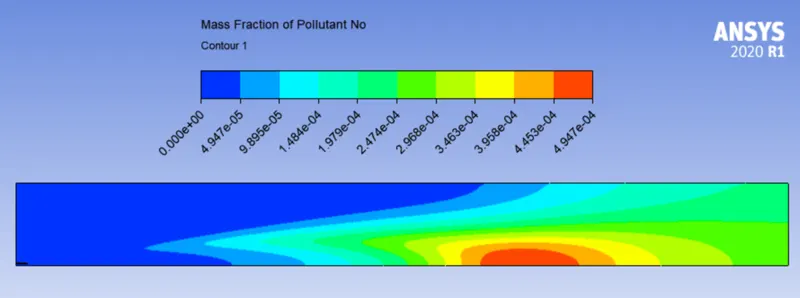
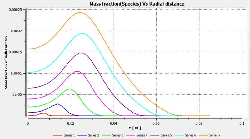
Soot mass fraction contour and plot -
Conclusion -
- From the contour plots, it can be seen that max dissociation of N_2 starts near the mid-region in the chamber. This is also where the flow reaches max temperatures.
- Line probes & line plots reveal that maximum soot production occurs approximately 325 mm away from the inlet near the axis of combustor.
- Radial distribution of 02 shows that combustion occurs mainly along the combustor axis.
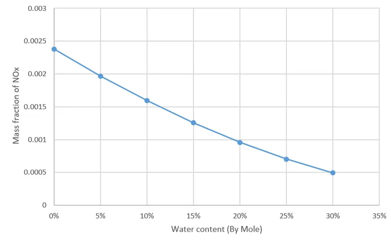
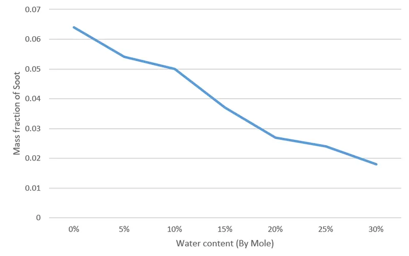
- The trends of max. temperature, NO & soot formation are shown below.
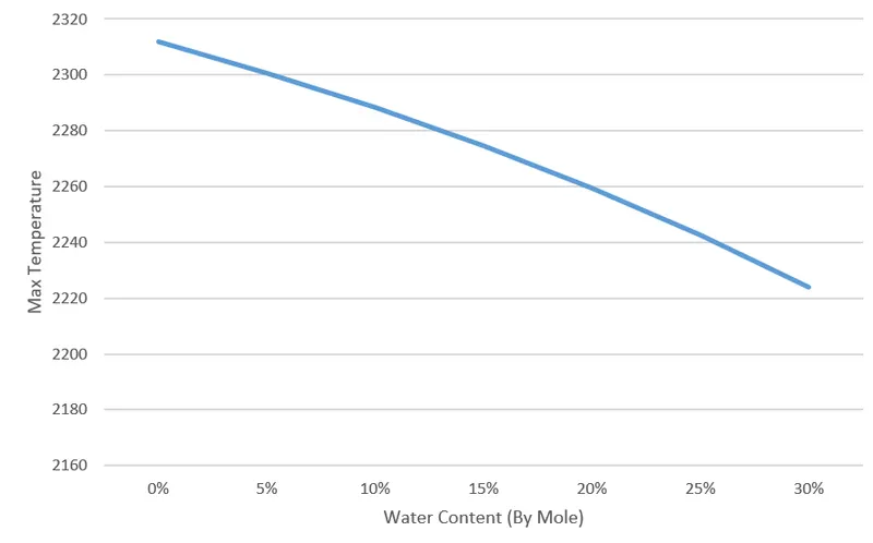
- As water absorbs latent heat during vaporization, the maximum combustion temperature reduces with water content.
- Most thermal NOx is formed in high-temperature stoichiometric flame pockets downstream of the fuel injectors where combustion air has mixed sufficiently with the fuel to produce the peak temperature fuel/air, hence max temperature reduction leads to NOx reduction at the outlet with water content.
- It is seen that water exponentially reduces soot formation in the combustor.