Simulating Combustion of Natural Gas in a cylindrical combustion chamber using species transport model in ANSYS Fluent.
AIM: To perform a combustion simulation on a given combustor model and to observe the variation of mass fraction of different species in the simulation.
OBJECTIVE:
Part 1
1) Perform a combustion simulation and plot the variation of mass fraction of different species in the simulation using a line probe at different locations.
2) Setup NOx and soot model to observe NOx emissions and soot formation.
Part 2
1) Add water content in the fuel from 5% to 30% by mole.
2) Provide necessary plots and contours from the CFD results.
INTRODUCTION: Combustion is defined as a chemical reaction in which a hydrocarbon fuel reacts with an oxidant to form products, accompanied by the release of energy in the form of heat. Being an integral part of various engineering applications like internal combustion engines, furnaces, and power station combustors, combustion exhibits itself as a wide domain during the design, analysis, and performance characteristics stages of the above-mentioned applications. To solve the complex equations from chemical kinetics and to yield information about the reaction mechanism, proper physical modeling has to be done. In this project, the combustion process is simulated with the help of CFD software ANSYS fluent. When the combustion is incomplete, various pollutants are formed, some pollutants are carbon dioxide, carbon monoxide, lead, and nitric oxide. In this project, the formation of pollutants from NOx emission which mainly consists of No, No2, N2o, and soot formation which is a mass of impure carbon particles are simulated and the variation of mass fraction of pollutants from NOx emission and soot formation with the addition of water into the fuel in studied.
Possible types of combustion simulations in FLUENT.
Computational fluid dynamics modeling of combustion calls upon the proper selection and implementation of a model suitable to faithfully represent the complex physical and chemical phenomenon associated with any combustion process. The model should be competent enough to deliver information related to the species concentration, their volumetric generation or destruction rate, and changes in the parameters of the system like enthalpy, temperature, and mixture density. The model should be capable of solving the general transport equations for fluid flow and heat transfer as well as the additional equations of combustion chemistry and chemical kinetics incorporated into that as per the simulating environment desired.
BASED ON MIXING
Non-Premixed Combustion: In this type of combustion, fuel and oxidizer enter the reaction zone in distinct streams. Mixing takes place at the time of combustion. Pre-Mixed Combustion: In this type of combustion, fuel and oxidizer are mixed at the molecular level before combustion.Partially Mixed Combustion: In this type of combustion, the fuel and oxidizer are partially pre-mixed at nonuniform ratios before combustion.
BASED ON PHASE
- Fluid Phase (Volumetric Reaction): Combustion takes place when the fuel is in the fluid phase.
- Wall (Surface Reaction): Combustion takes place on a wall or the surface.
- Particle (Surface Reaction): Combustion takes place on the surface of the particles.
POROUS REGIONS: Combustion takes place inside the pores.
Eddy Dissipation Model :
This model is used when turbulent mixing of the constituents has to be taken into consideration. The k/Ɛ turbulent time scale is used to calculate the reaction rate. A comparison between the turbulent dissipation rates of the fuel, oxidant, and products is done and the minimum amongst all is taken as the rate of the reaction. The transport equations for the mass fractions of the constituents are solved using this rate of reaction. Apart from this a mean enthalpy equation is also solved and temperature, density, and viscosity are calculated accordingly. The model can also be implemented when a finite rate kinetically controlled reaction is to be simulated. In such a situation, while deciding the rate of the reaction the Arrhenius kinetic rate expression is also taken into account and the rate of reaction is taken as a minimum amongst the turbulent dissipation rates of all the constituents and the Arrhenius kinetic rate expression. Since turbulent mixing governs the characteristics of this model, there exists a limit to the quality of the combustion simulation depending upon the type of the turbulent model implemented to represent the flow. The model can also be modified to account for the mixing of fine structures during the turbulent reaction. This modification of the model results in the eddy dissipation model which considers the mass fraction of fine structures in its calculations.
Combustion simulation on the model
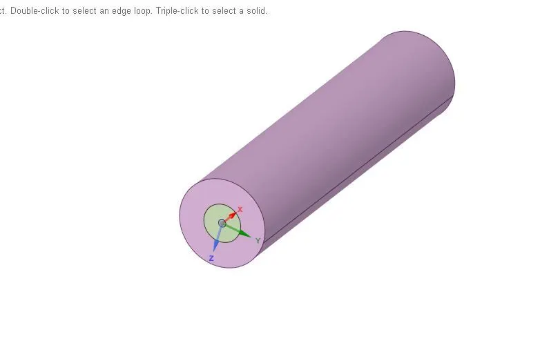
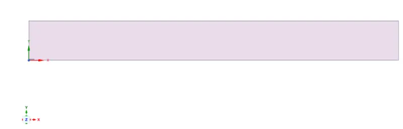
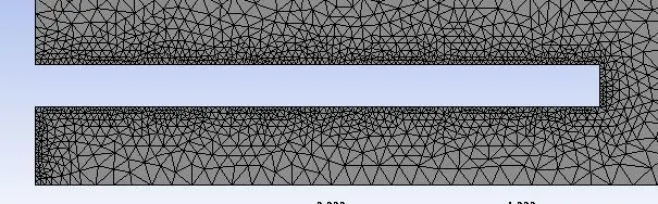
Finding the result using this 3D model will increase the computational cost and time to run the simulation and also in an Academic license there are limitations for mesh generation. So we are extracting the 2D model from the 3D model and doing a simulation on it.
MESHING
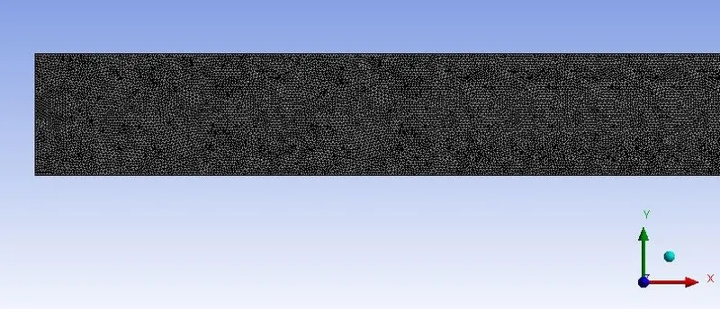
For refining the mesh for this case we are using the all triangle method.
- Element size = 1.5 mm
- Capture proximity ON
- Proximity minimum size = 0.025 mm
- Number of cells across gap = 4
- Number of Nodes = 19850
- Number of Elements = 38515

SIMULATION SETUP:
Setting up the physics for Combustion in ANSYS fluent.
- Solver: For this case, we are using a pressure-based Steady-state solve
- Velocity formulation - Absolute
- 2D space - Axisymmetric
Follow the Energy Equations
- Viscous Model
model - k-epsilon
- SpeciesModel -
The species model in ANSYS Fluent allows for the modeling of the mixing and transport phenomena for different chemical species through a solution of conservation equations including convection, diffusion and reaction source(s) terms for each of the component species involved for the given set of reactions. During the solution of conservation equations, ANSYS Fluent evaluates the local mass fraction of each species for the total number of species involved in the reaction by solving for the diffusion flux of species as a result of fluctuations in its concentration and temperature using Fick's Law in the case of laminar flows while introducing the turbulent Schmidt number SctSct for turbulent flows. Additionally, transport of enthalpy at the time of species diffusion is also accounted for due to its impact on the enthalpy field by providing for the necessary treatment along with the diffusion of species at the inlet. The reaction rates for the given computational problem are determined by using the eddy-dissipation model in which turbulence or turbulent mixing is considered over the effect of the chemistry timescales thereby avoiding the Arrhenius chemical calculations which are expensive to perform making this approach computationally cheaper. The chemical reaction rate of the eddy-dissipation model is controlled by the large-eddy mixing time scale, kεkε of the k-εε turbulence model, such that combustion takes place when its value is greater than 0 and therefore does not require an ignition source.
Setup of the Species model:
The Species model is found in the same location as the Viscous model. The options enabled included selecting 'Model' as 'Species Transport', and 'Reactions' as "Volumetric" because we are dealing with the amount or concentration of species by its volumetric presence, and such an analysis is usually employed in determining the composition of fuel gases and combustion products, 'Chemistry Solver' to 'None-Explicit Source' as chemistry source terms were being used in the species transport equations, "Inlet Diffusion" and "Diffusion Energy Source" were checked under "Options" to take into consideration the diffusion flux of species at the inlet and the effect of transport of enthalpy as a result of diffusion of species in the energy equation, and 'Turbulence-Chemistry Interaction' as "Eddy-Dissipation". 'Mixture Material' for the given numerical analysis was set to "methane-air" and "methane-air-2step" with the latter allowing for the addition of water, in this case in the fuel.
 ......................... (eq.1)
where
`ar(underset( 2)(O)+3.76⋅underset( 2)(N)) `represents the number of moles of air reacting with methane to form the end combustion products as seen on the right-hand side of (Eq. 1). Since, O2O2 occupies almost 21% by the volume in the air while N2 occupies almost 79%, the resulting combination of O2 and N2 is expressed as the second term on the left-hand side of (Eq. 1). In order to derive the quantitative relationship between products and reactants, stoichiometric coefficients are required to be determined which is done by balancing the number of moles of each atom on either side of (Eq. 1) to develop the following equalities:
`1=a`
`ar=2*a+b`
`4=2b` and
`3.76*ar=c`
evaluating the above expressions, we get values of a number of moles for 'a' (representing carbon) as 1, 'b' (representing hydrogen) as 2, 'ar' (representing air mixture) as 2 and 'c' (representing nitrogen) as 7.52. The specification of the derived values of 'a', 'b', and 'c' in reference to mole fraction can be expressed as follows:
At the inlet allowing only entry of fuel, methane will be injected or driven into implying the mole fraction of CH4 species at this boundary is 1 which is also the same value in the case of the mass fraction. However, at the inlet permitting entry of air stream, the number of moles of components comprising the air mixture is the sum of two moles of O2 species and 7.52 moles of N2 species equating to a combined total of 9.52 moles. Therefore, the mole fraction of O2O2 species in the air is the ratio of the number of moles of O2 species to the total number of moles in the air i.e., `2/9.52=0.2129` while the mole fraction of N2 species in the air is the ratio of the number of moles of N2 species to the total number of moles of air i.e., `7.52/9.52=0.797`.
The molar mass of one mole of O2 species is 16g/mol equating to a mass of two moles of the same as 32 grams while the molar mass of one mole of N2 species is 14g/mol equating to a mass of 7.52 moles of the same as 105.28 grams and their combined mass sums to a total of 137.28 grams. Therefore, the mass fraction of O2 species in the air is the ratio of the mass of O2 species to the total mass of air i.e., `32/137.28=0.23` while the mass fraction of N2 species in the air is the ratio of the mass of N2 species to the total mass of air i.e., `105.28/137.28=0.77`. In the case of the methane-air-2step mixture model and to add water content in the fuel from 5% to 30% by mole, the mass fraction of CH4 species is reduced in intervals of 0.05 while the mass fraction of H2O species is conversely increased by the same intervals.
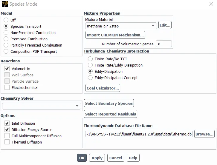
- Species Transport
- Reactions - Volumetric
- Chemistry solver - None-Explicit source
- Options - Inlet diffusion, Diffusion Energy Source
- Mixture Material - methane-air
- Turbulence-Chemistry Interaction - Eddy-Dissipation
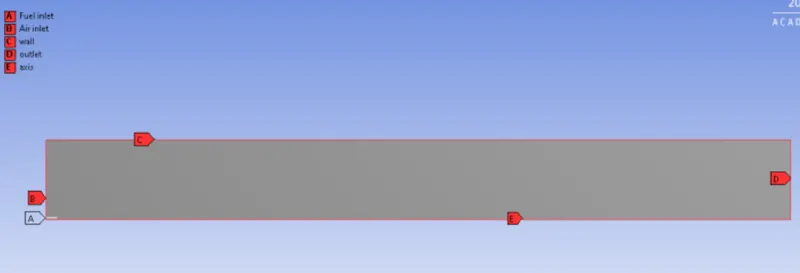
Air-Inlet
- Velocity = 0.5 m/s
- Temperatures = 300 K
- Species mass fraction = O2 - 0.23
Fuel-Inlet
- Velocity = 80 m/s
- Temperatures = 300 K
- Species mass fraction = CH4 - 1
Outlet
pressure-outlet = 0 pascal (gauge pressure)
Soot Model
The Soot model is used for determining the formation of soot by calculating its concentration typically utilized for combustion systems such as in the case of the given numerical analysis.
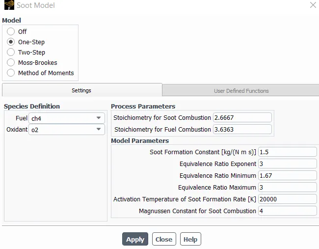
Soot model is available for setup only when the Species model is activated and is found in the Models section under the Physics Tab. In the soot model window, the 'Model' enabled was "one-step" with 'Fuel' selected as `Cunderset( 4)(H)` species and oxidant as `underset( 2)(O)` species under the 'Species Definition' section of the 'Settings' tab while the remaining parameters were retained to their default values. The "one-step" is the default soot prediction model developed by Khan and Greeves [1][4] that evaluates the rate of soot formation on the basis of an empirical relation through the solution of a single transport equation for the soot mass fraction.
NOx Model
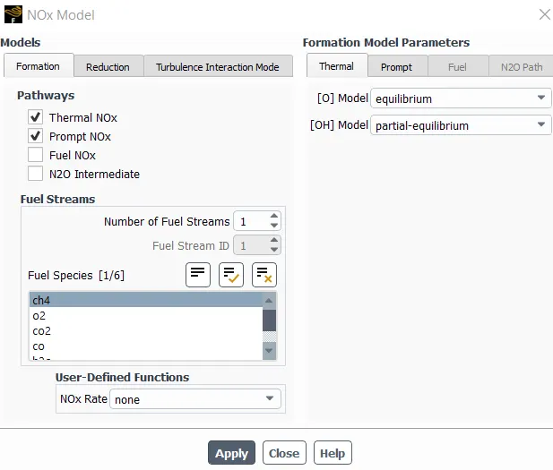
The NOx model is turned on which helps in predicting the formation of pollutant No in the process of combustion. The NOx formation takes place by the oxidation of atmospheric nitrogen present in the combustion air hence, thermal NOx is enabled. The prompt NOx is enabled as the high-speed reactions at the flame front cause NOx formation.
The NOx model was available for setting up in the same location as the soot model and only after the Species model was activated. In the NOx model window, 'Thermal NOx' and 'Prompt NOx' pathways were checked and fuel species were selected as CH4 with the rest of the variables retaining their default values. Similar to the soot model, a transport equation is required to be solved for determining the nitric oxide (NO) concentration from the evaluated flow field and solution of combustion properties. Thermal NOx accounts for the product(s) formed as a result of the chemical reaction of oxidation of atmospheric nitrogen in the combustion air while Prompt NOx refers to the products formed at a rapid rate in the presence of the combustion flame generally taking place between hydrocarbon radicals and molecular nitrogen to give rise to intermediate groups like HCN and CN that eventually decays to form NO.
In part 1 of the simulation, the mass fraction of H2o is 0 and Ch4 is 1 at the fuel inlet and in part 2, the mass fraction of H20 is increased from 5% to 30% by mole. The results obtained from the simulation are discussed below.
RESULTS
Residual Plots
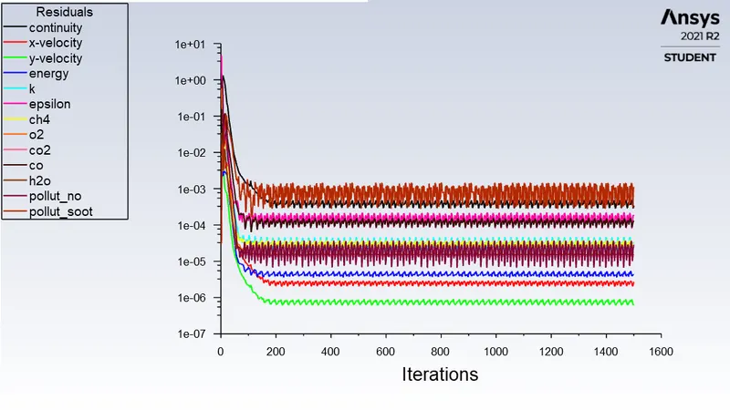
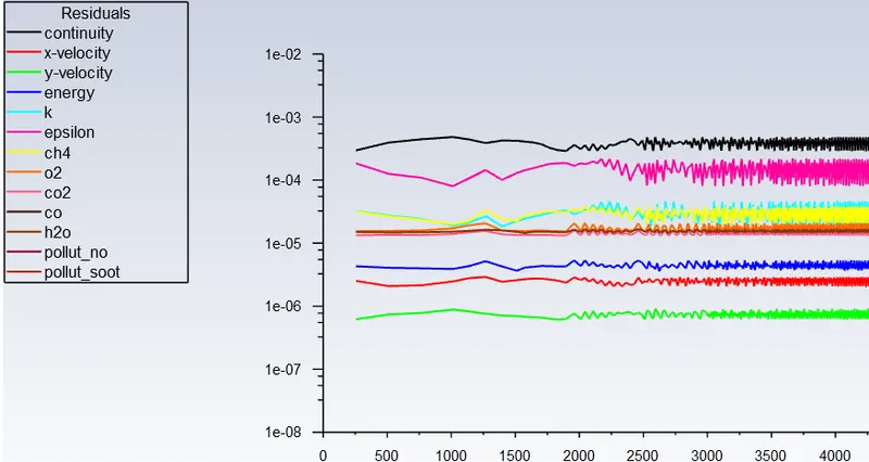
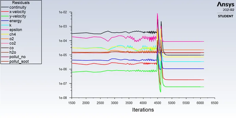
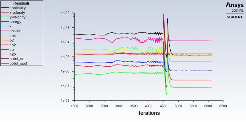
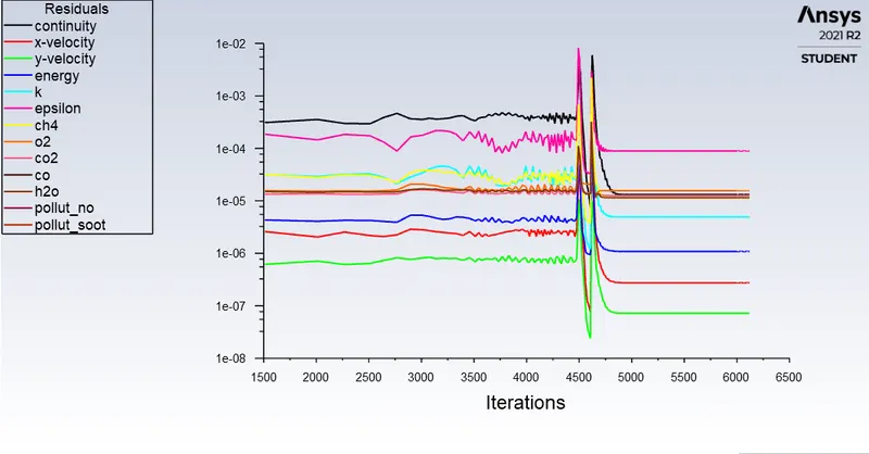
By looking at the residuals iterations of 1500 can be confirmed as converged.
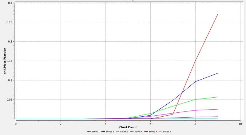
Line probes at different locations of the combustor

________________________________________________________________________________________________
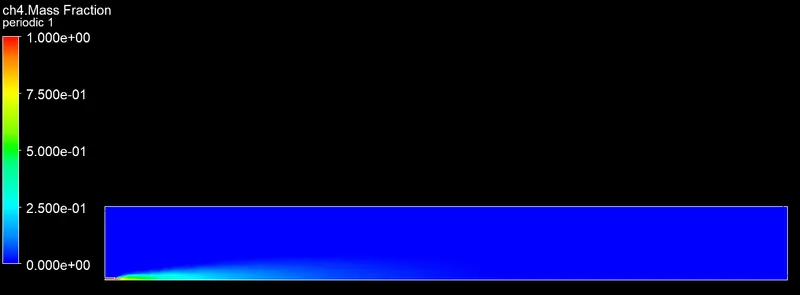
Mass Fraction of CH4
_______________________________________________________________________________________________
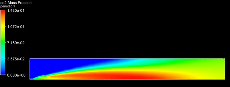
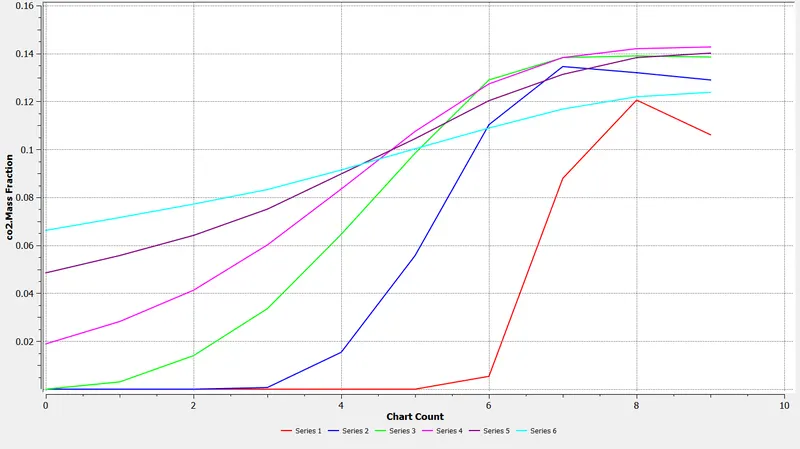
Mass Fraction of Co2
_______________________________________________________________________________________________
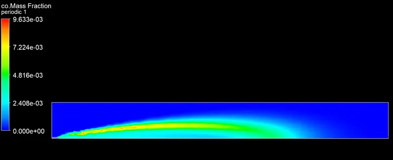
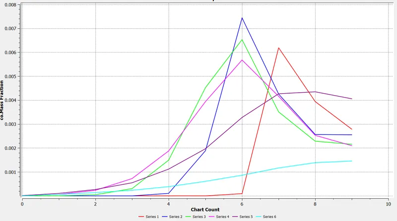
Mass Fraction of CO
 ______________________________________________________________________________________________
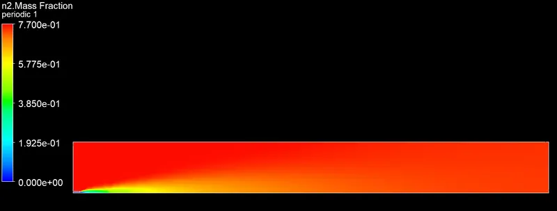
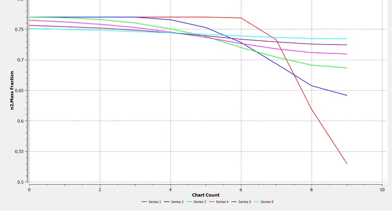
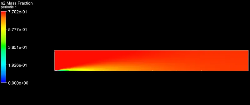
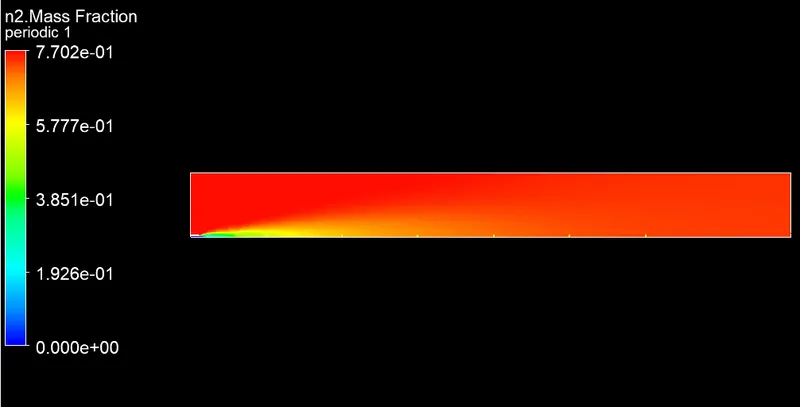
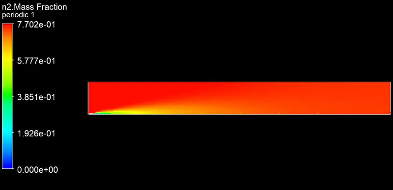
Mass Fraction of N2
_____________________________________________________________________________________________
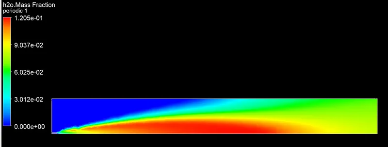
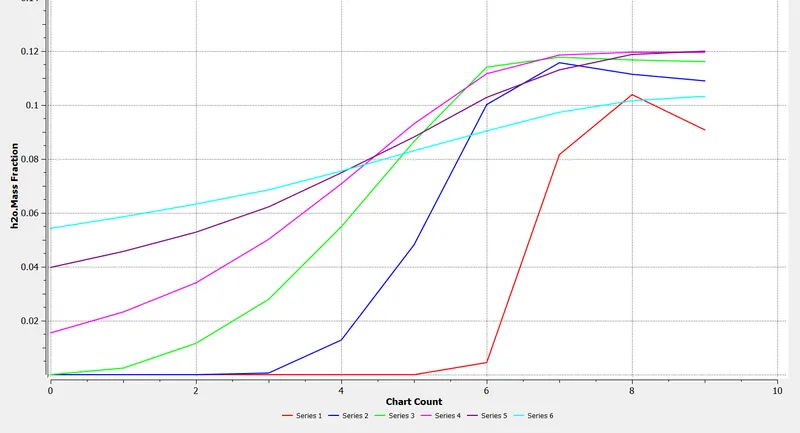
Mass Fraction of H2o
 _____________________________________________________________________________________________
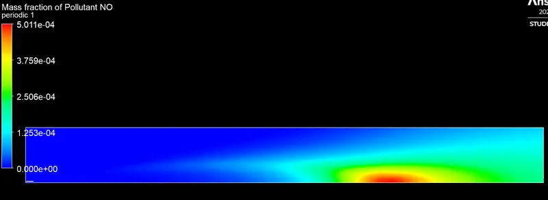
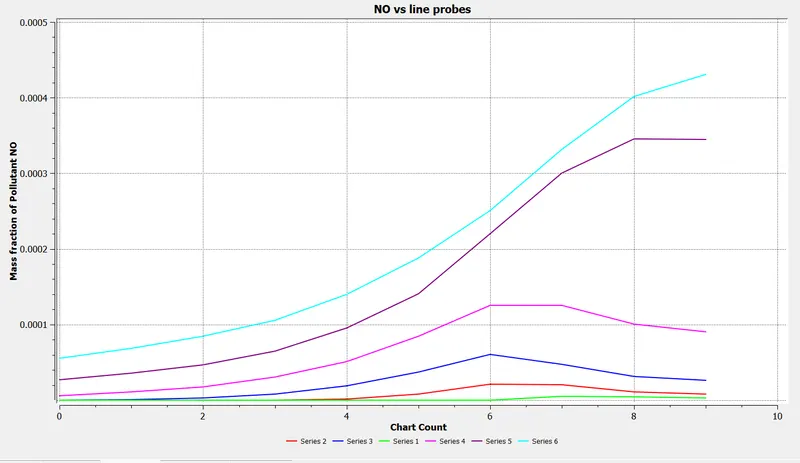
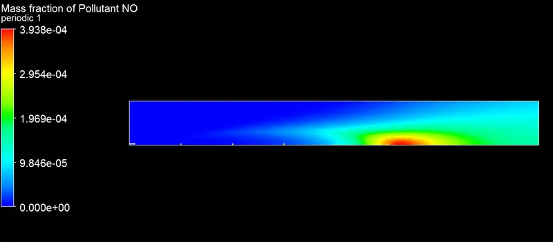
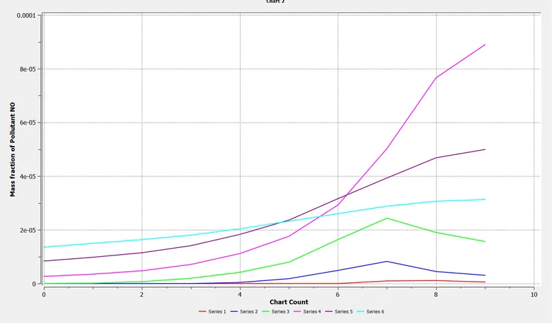
Mass Fraction of NOx
 _____________________________________________________________________________________________
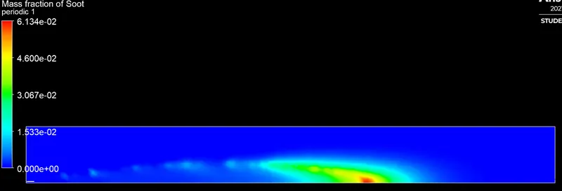
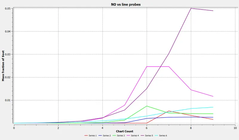
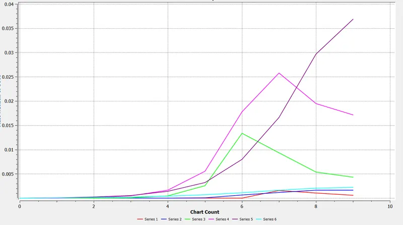
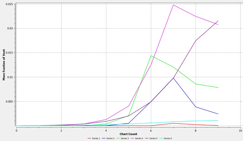
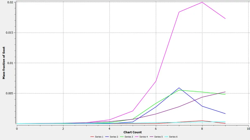
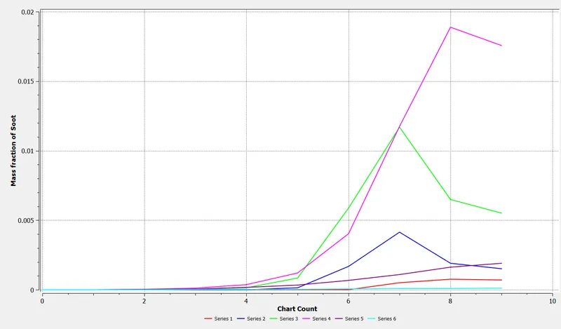
Mass Fraction of Soot
 _____________________________________________________________________________________________
OBSERVATIONS FROM PART 1 SIMULATION
1. In the temperature contour, it can be seen that the highest temperature is observed ahead of the inlet of the combustor where the mixing of fuel-air mixtures takes place.
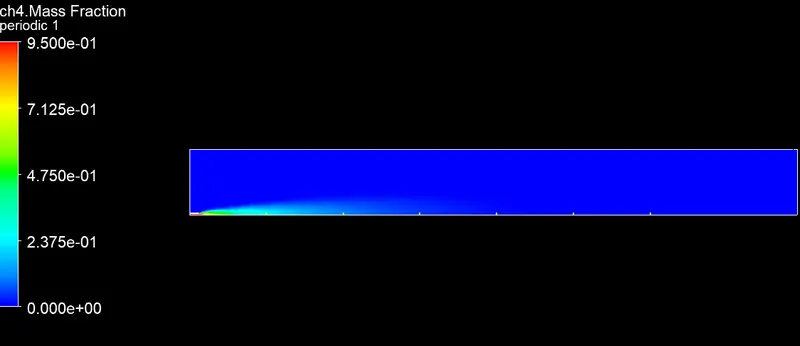
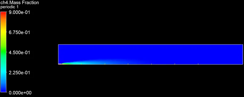
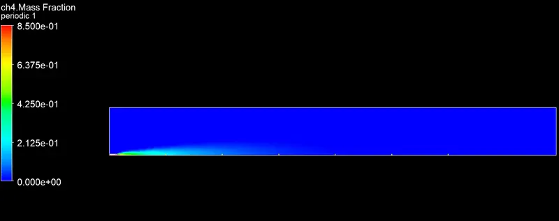
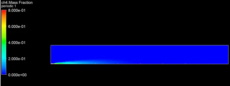
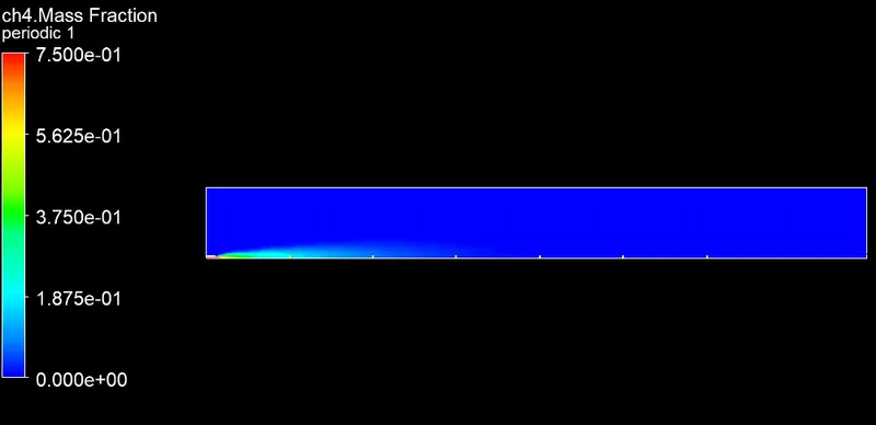
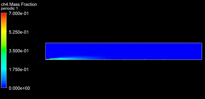
2. In the Ch4 mass fraction contour, the highest mass fraction of Ch4 is observed near the fuel inlet where the fuel is discharged and as combustion takes place Ch4 mass fraction decreases.
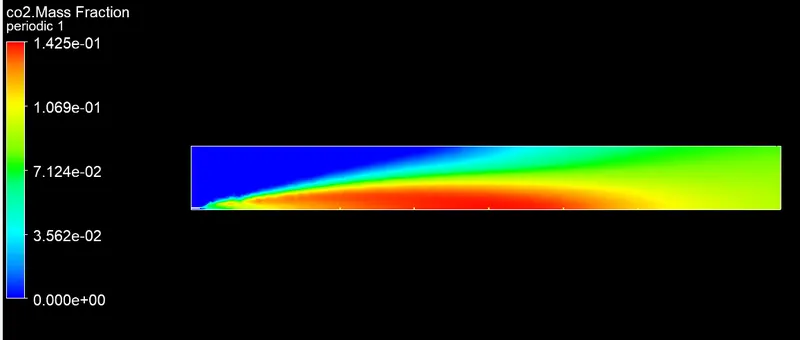
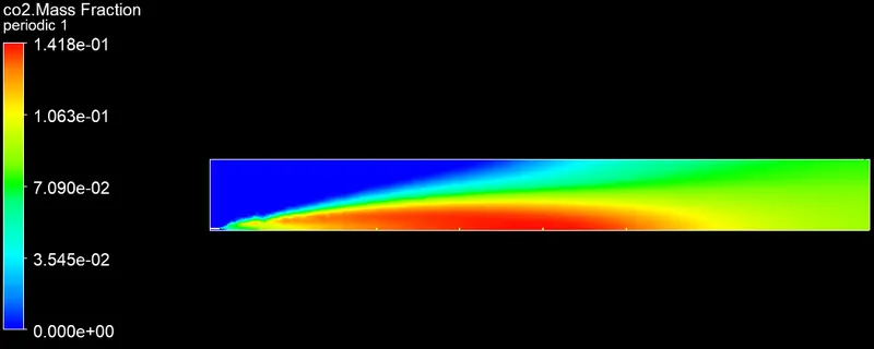
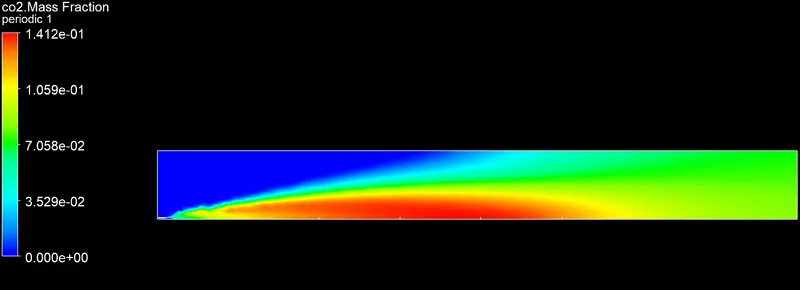
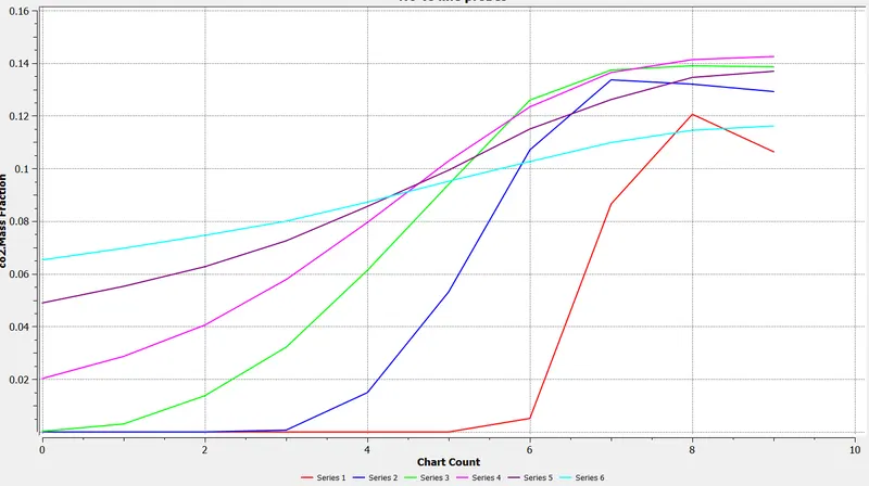
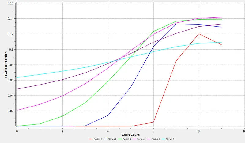
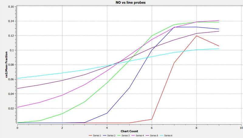
3. the Highest mass fraction of Co2 and H2o is observed in the high-temperature zone.
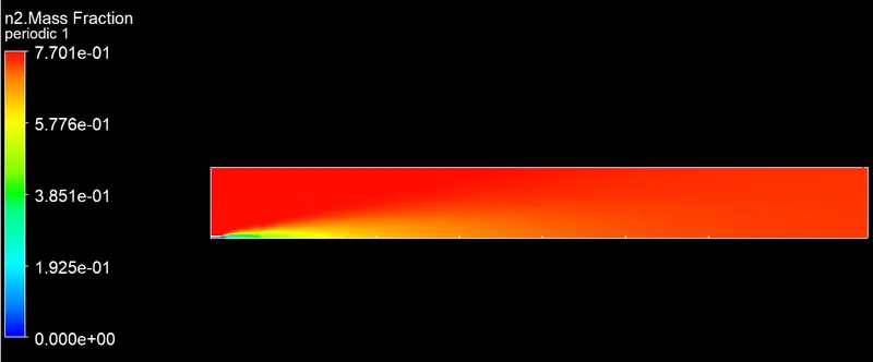
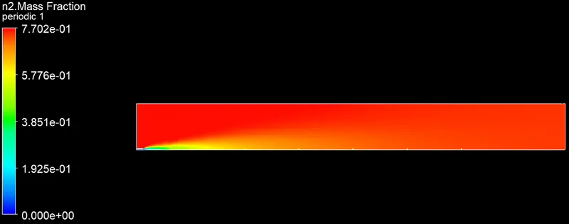
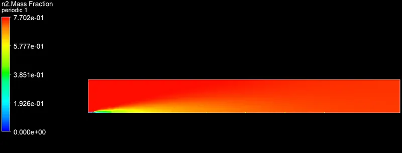
4. From the N2 mass fraction contour, it can be seen that the N2 is almost distributed uniformly across the combustor.
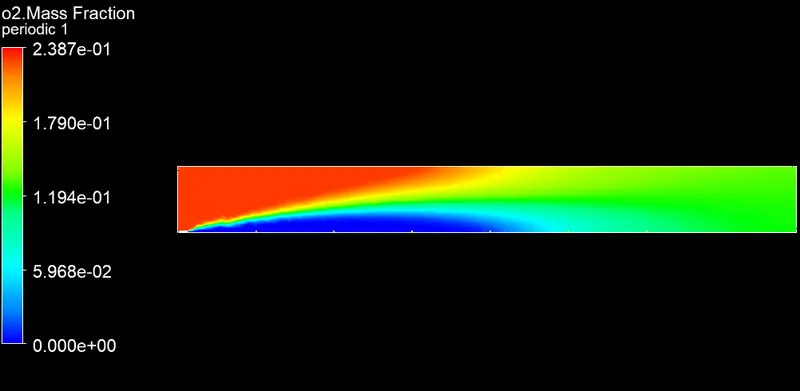
5. The oxygen mass fraction is highest near the air inlet.
6. The pollutant like Nox and soot mass fraction is more near the outlet of the combustor.
Part 2
Boundary conditions
Air inlet
Velocity = 0.5 m/s T
Temperature = 300 K
Species
| Species | Species mass fraction |
| CH4 (Methane) | 0 |
| O2 (Oxygen) | 0.23 |
| CO2 (Carbon-di-oxide) | 0 |
| CO (Carbon Monoxide) | 0 |
| H2o (water) | 0 |
Fuel inlet
Velocity = 80 m/s
Temperature = 300 K
Species
| Species | Species mass fraction |
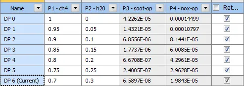
| CH4 (Methane) | Parameter 1 |
| O2 (Oxygen) | 0 |
| CO2 (Carbon-di-oxide) | 0 |
| CO (Carbon Monoxide) | 0 |
| H2o (water) | Parameter 2 |
Top surface
Boundary type = wall
Axis
x-axis = axisymmetric
Output parameters
| Parameter 3 | Nox mass fraction |
| Parameter 4 | Soot mass fraction |
_____________________________________________________________________________________________
Results of part 2
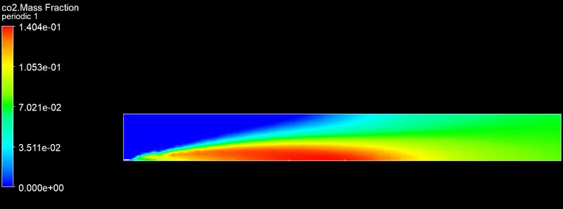
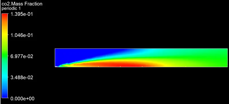
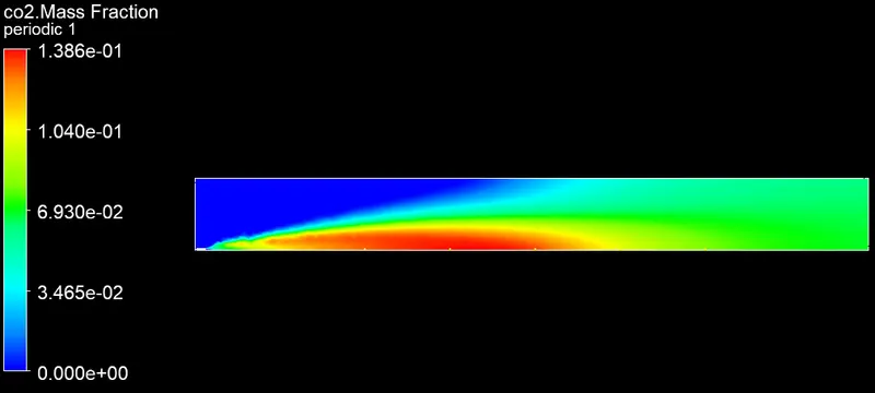
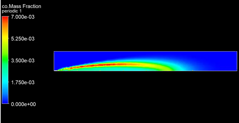
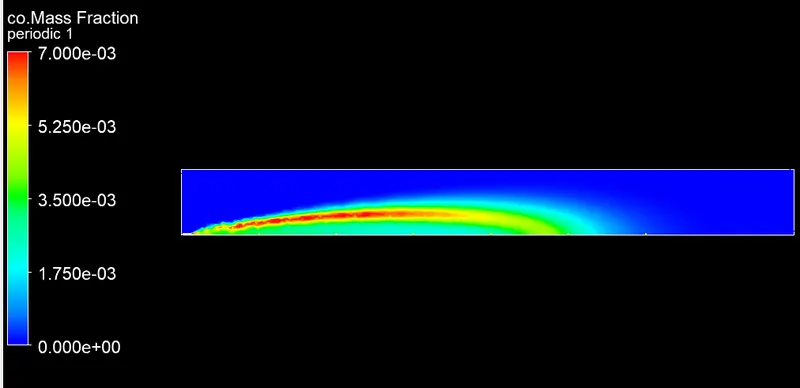
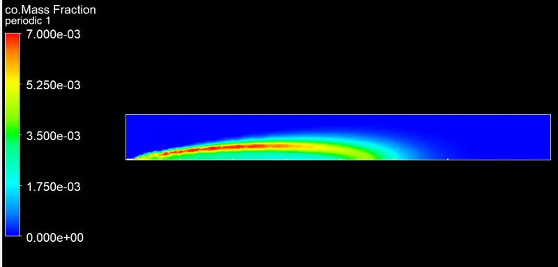
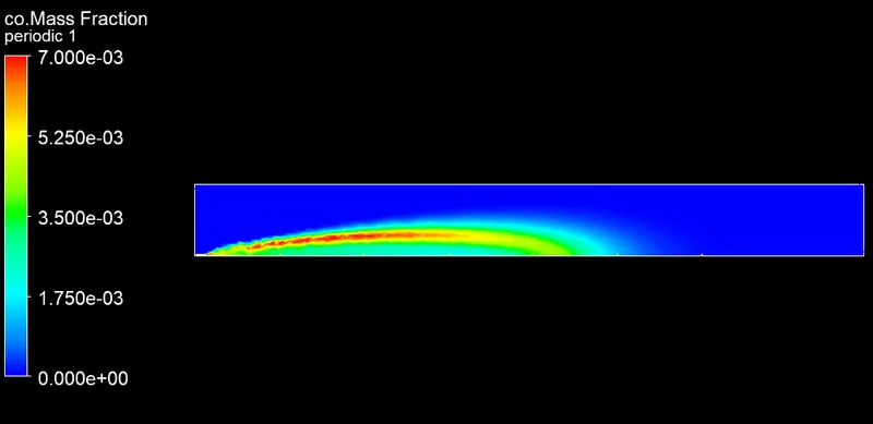
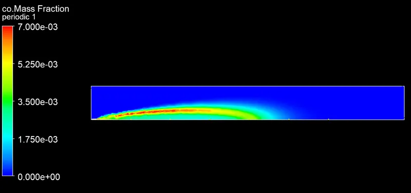
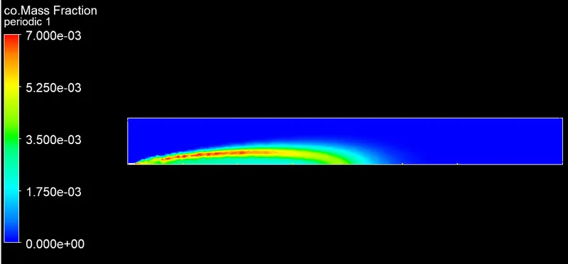
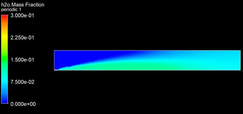
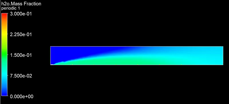
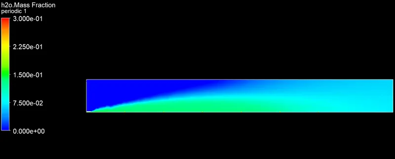
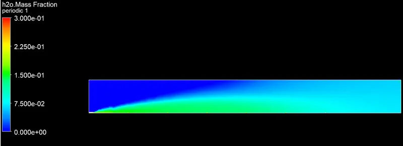
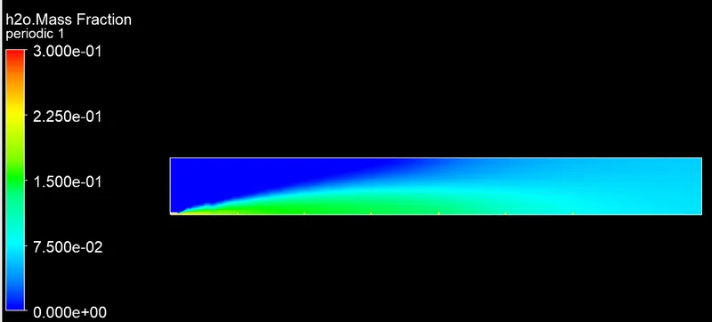
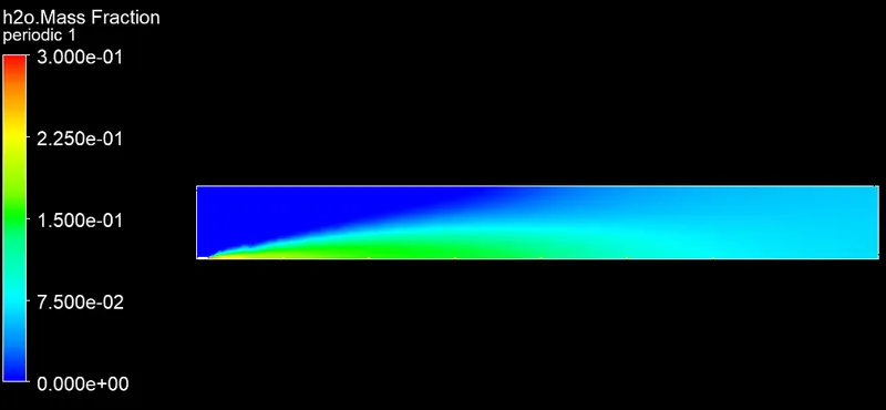
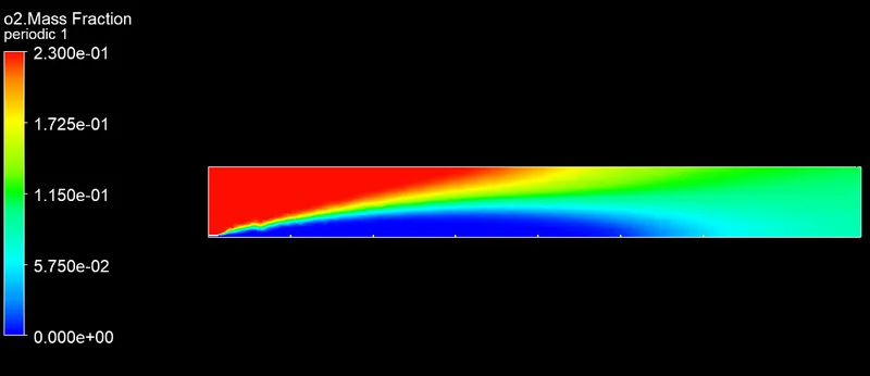
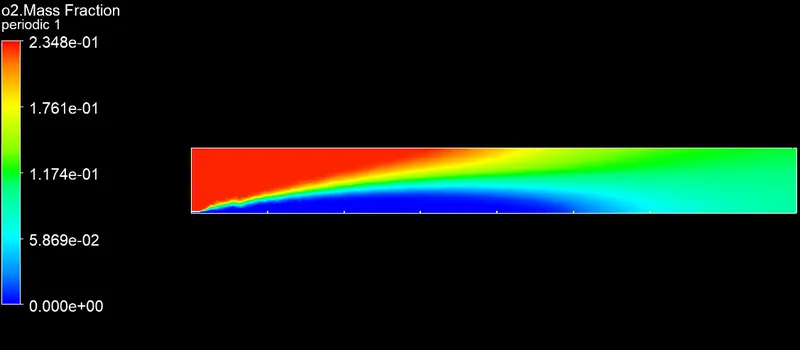
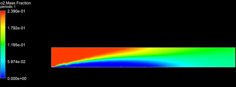
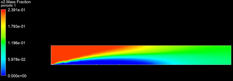
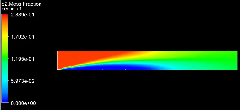
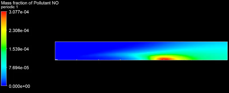
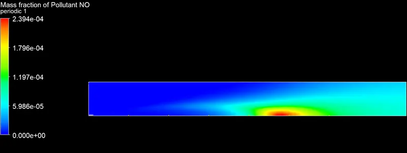
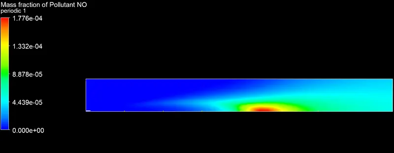
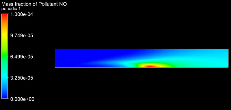
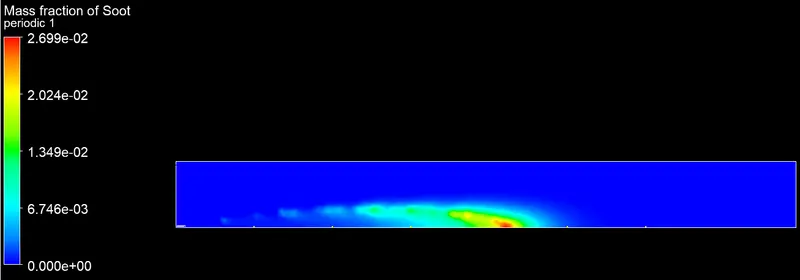
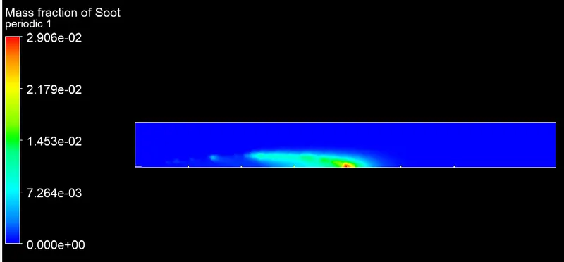
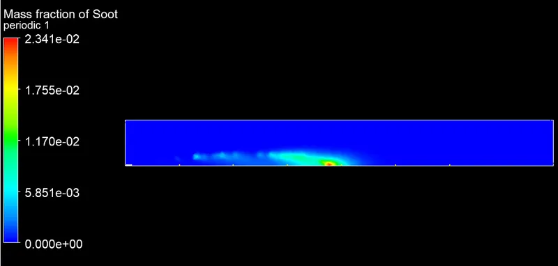
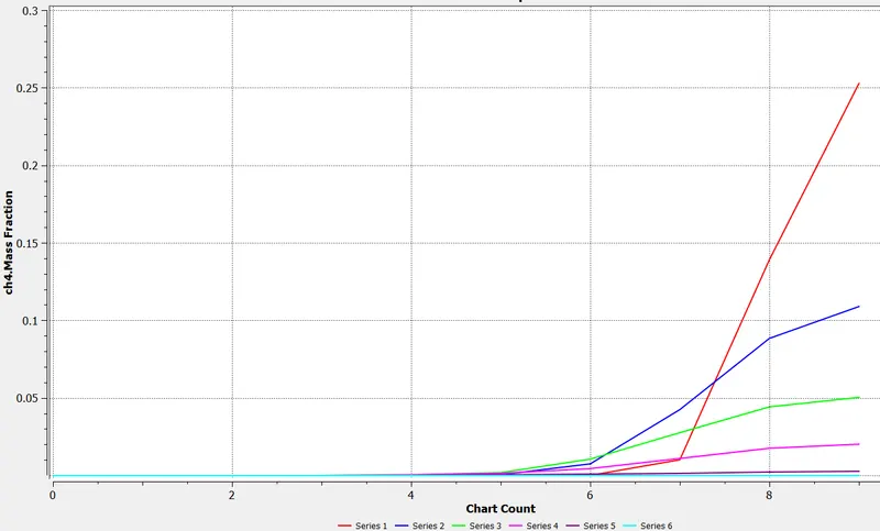
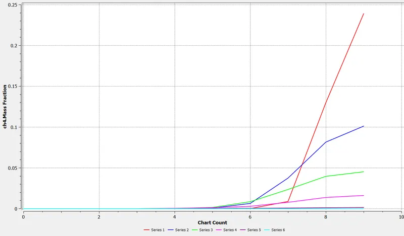
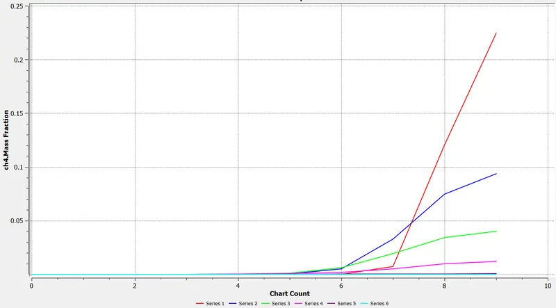
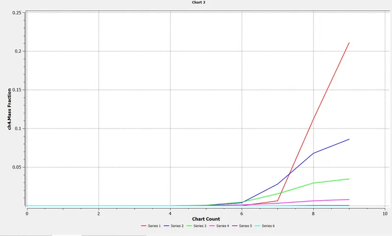
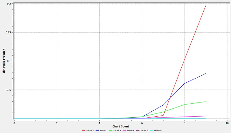
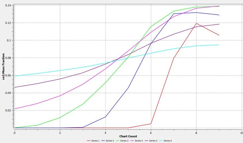
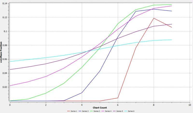
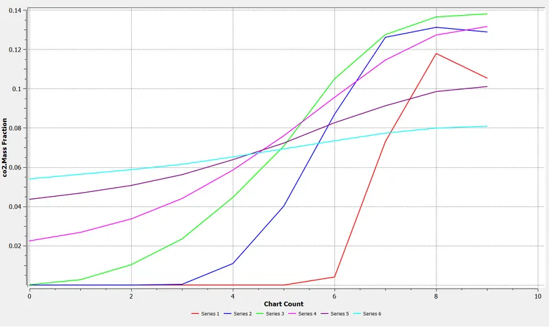
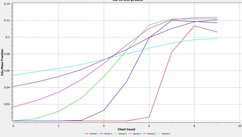
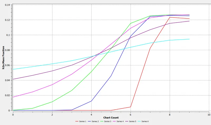
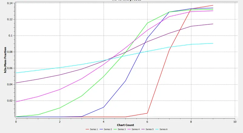
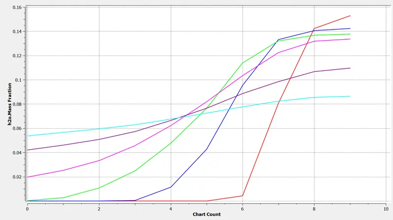
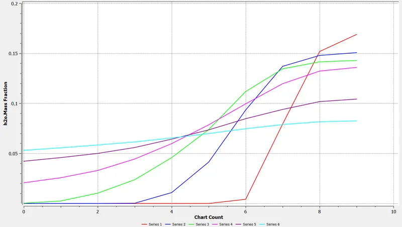
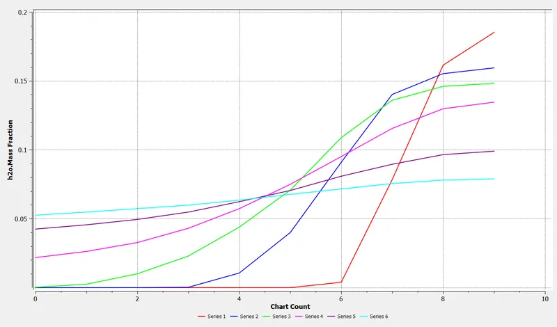
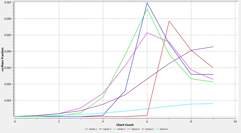
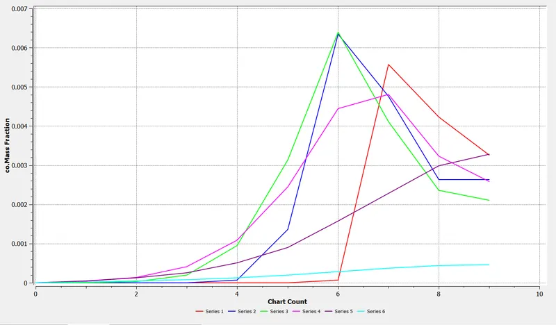
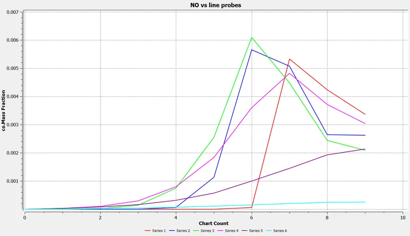
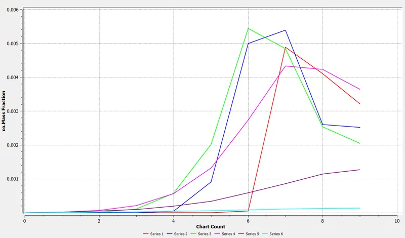
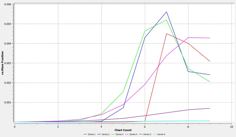
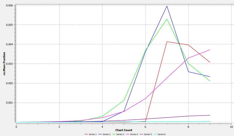
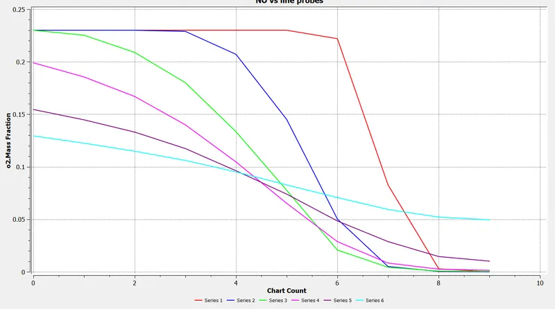
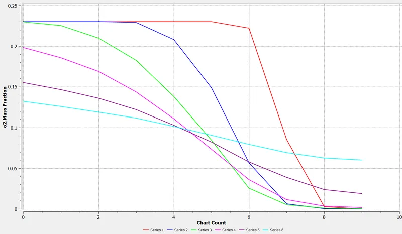
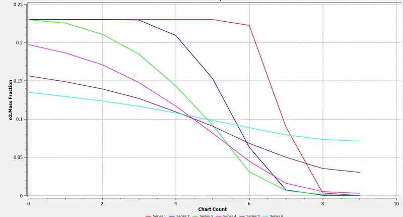
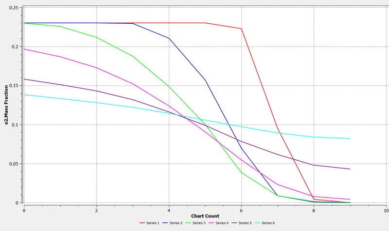
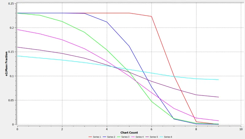
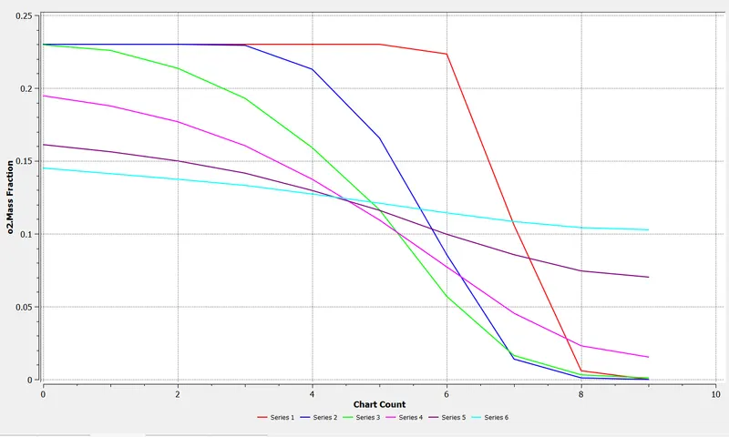
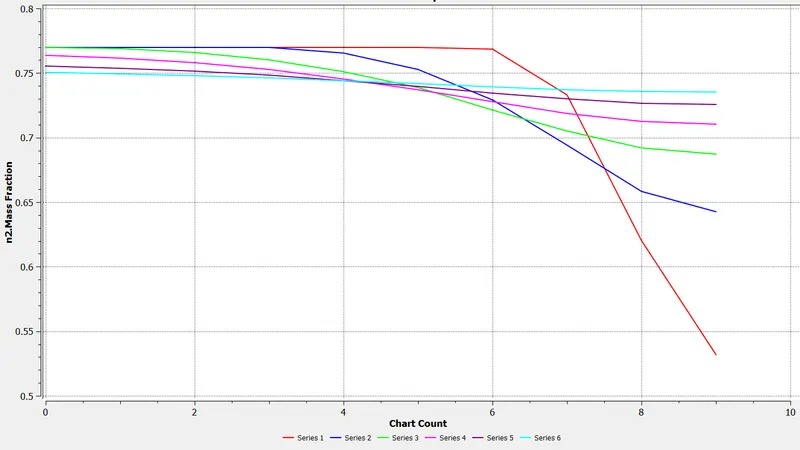
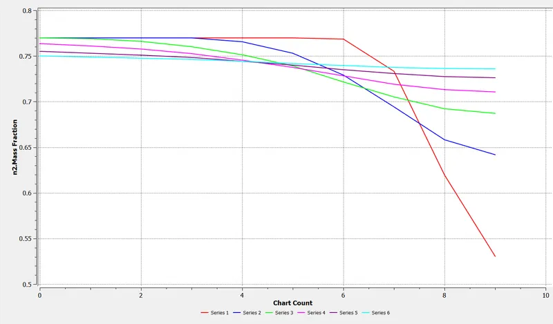
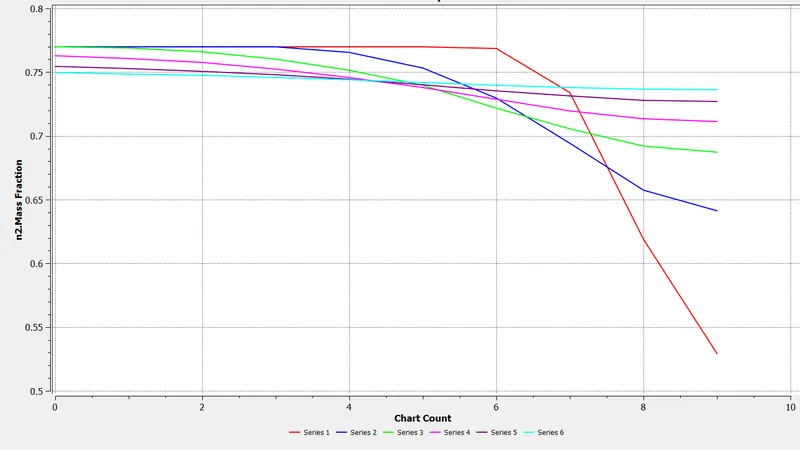
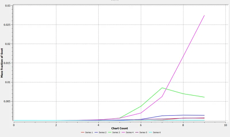
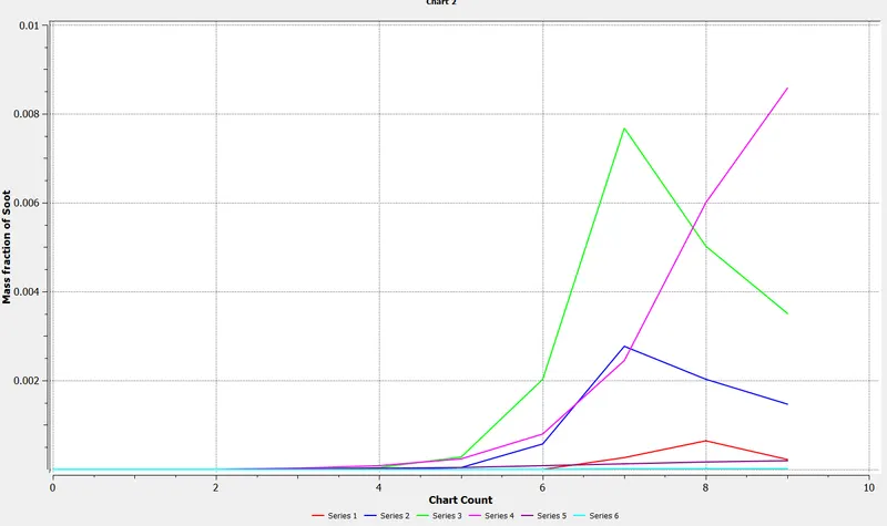
Mass Fraction plots along for different water content values in the fuel by mole [a) 0%, b) 5%, c) 10%, d) 15%, e) 20%, f) 25%, g) 30%]
Residuals
________________________________________________________________________________________________
MASS FRACTION CONTOURS OF CH4
________________________________________________________________________________________________
MASS FRACTION OF CONTOURS OF CO2
________________________________________________________________________________________________
MASS FRACTION CONTOURS OF CO
________________________________________________________________________________________________
MASS FRACTION CONTOURS OF H2O
________________________________________________________________________________________________
MASS FRACTION CONTOURS OF O2
________________________________________________________________________________________________
MASS FRACTION CONTOURS OF N2
________________________________________________________________________________________________
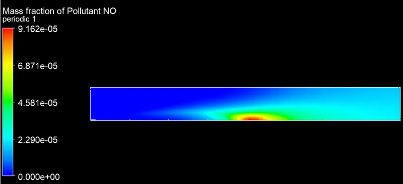
MASS FRACTION CONTOURS OF NOx
________________________________________________________________________________________________
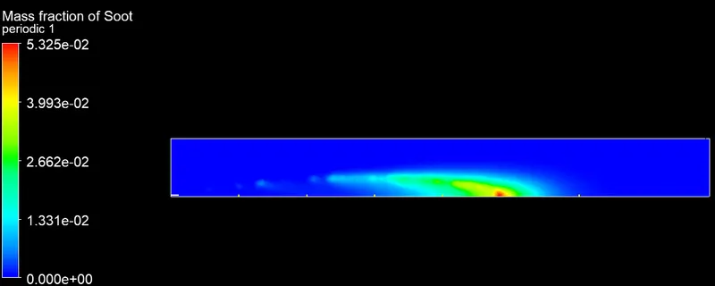
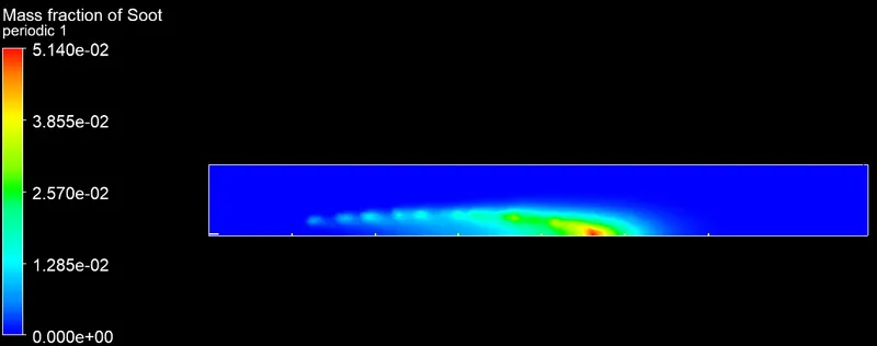
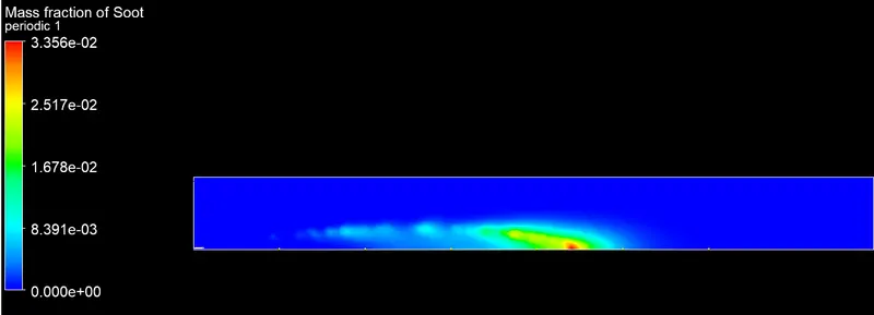
MASS FRACTION CONTOURS OF SOOT
 ________________________________________________________________________________________________
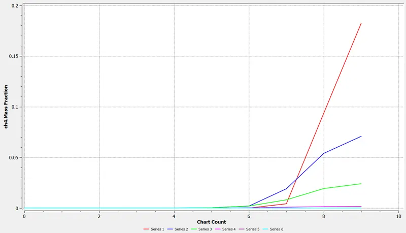
MASS FRACTION LINE PLOTS OF CH4
________________________________________________________________________________________________
MASS FRACTION LINE PLOTS OF CO2
________________________________________________________________________________________________
MASS FRACTION LINE PLOTS OF H2O
________________________________________________________________________________________________
MASS FRACTION LINE PLOTS OF CO
________________________________________________________________________________________________
MASS FRACTION LINE PLOTS OF O2
________________________________________________________________________________________________
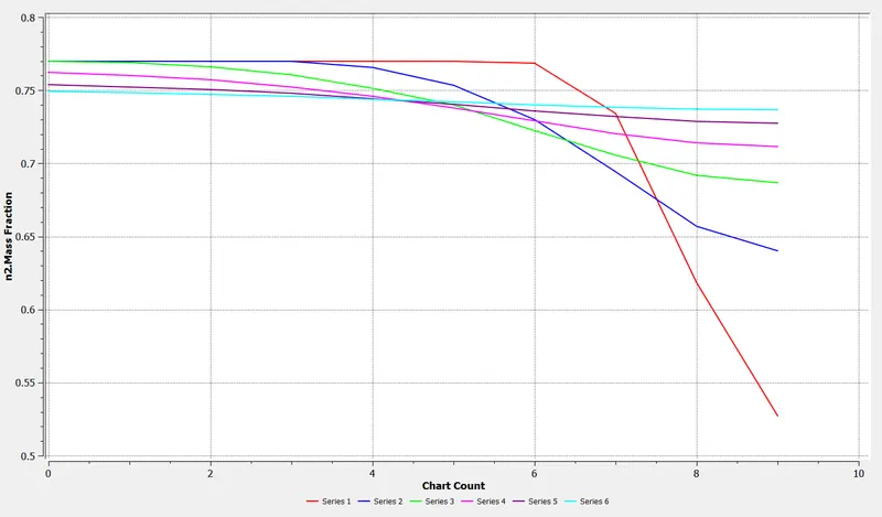
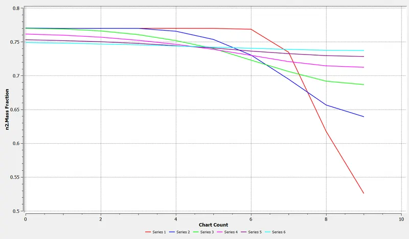
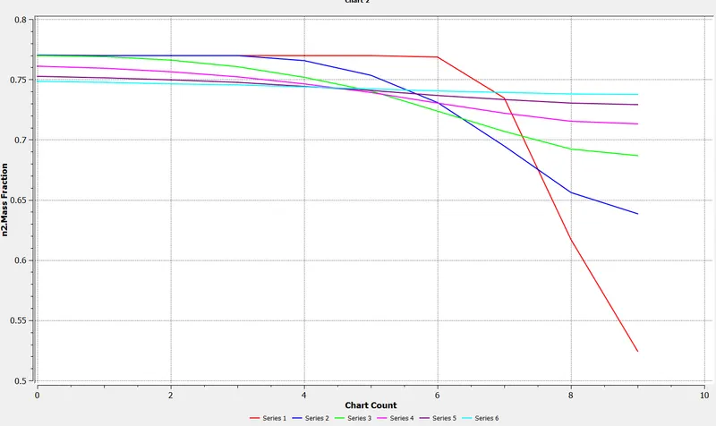
MASS FRACTION LINE PLOTS OF N2
________________________________________________________________________________________________
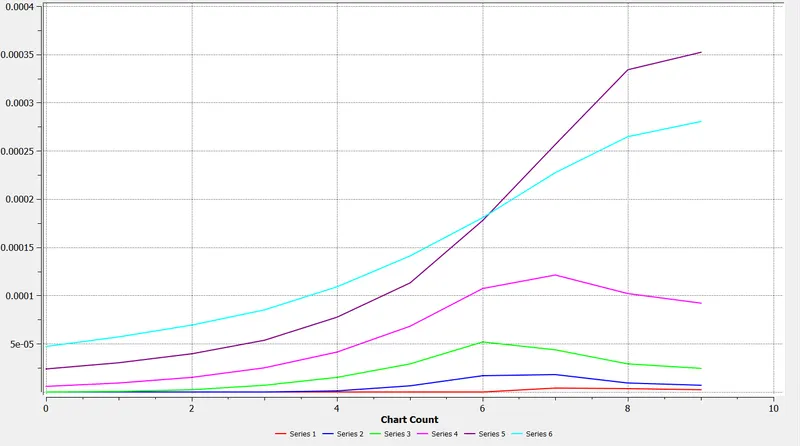
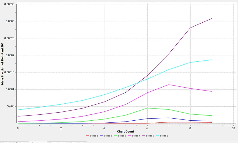
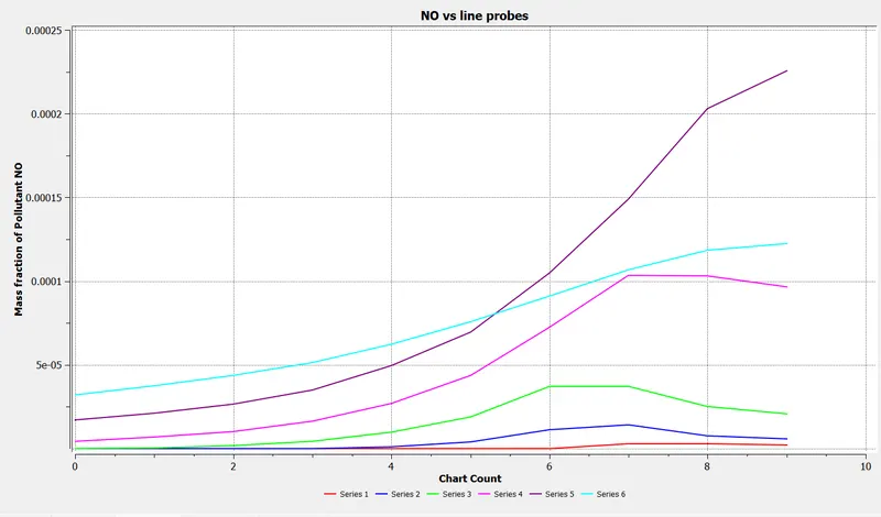
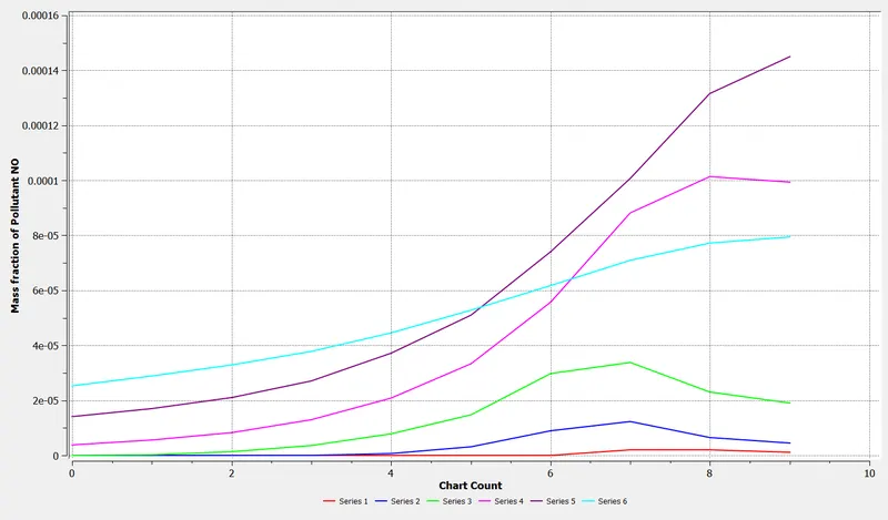
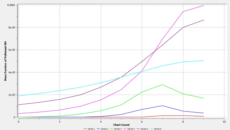
MASS FRACTION LINE PLOTS OF NOx
________________________________________________________________________________________________
MASS FRACTION LINE PLOTS OF SOOT
PARAMETRIC STUDY
OBSERVATIONS FROM PART 2 SIMULATION
1. The temperature drops from 2302 K to 2229 K as the water content is increased from 5% to 30% in the fuel.
2. The mass fraction of Co increases from 0.02 to 0.04 as the water content is increased in the fuel.
3. No variation of N2 and O2 mass fraction is observed.
4. The mass fraction of pollutants like NOx and soot decreases as the water content in the fuel is increased.
CONCLUSION
The numerical analysis for the given combustor model under steady-state conditions for rich fuel conditions and different values of water content in the fuel by mole, using the Realisable k-ε turbulence model, Species model, and NOx and soot models in ANSYS Fluent 2021 was well understood. It was realized that for a sufficient value of the large-eddy mixing time scale, kε, a combustion process could be initiated and driven by turbulence using the eddy-dissipation model, and the presence and concentration of different species, in terms of their mass fractions, involved could be visualized both along and across the combustor model. A significant decrease in the mass fraction of soot and NOx species was observed due to the addition of varying water content in the fuel by mole, however, this technique also tends to enhance the presence of CO (carbon monoxide) and HC levels during emissions beyond a certain limit which is its major drawback. Moreover, the water needs to be treated before being used in fuel depending on the application, which presents its own challenges in terms of storage, pumping, and handling of water also varying in capacity therefore this approach has largely been employed in standalone industrial plants that are often located near the vicinity of a large reservoir.