Week 10: Project 1 - FULL HYDRO case set up (PFI)
OBJECTIVE:FULL HYDRO SIMULATION OF PFI ENGINE
SPRAY MODELLING:
Generally there are two spray solvers
1.Eulerian solver
2.Lagrangian solver
For gaseous spray eulerian solver is used and for liquid spray lagrangian solver is used .Lagrangian solver is used to model discrete parcel whereas eulerian solver is used to model continuous fluid domain
In eulerian solver species mass fraction and mass flow rate is set at inflow boundary.Parcels are the collection of drop into the domain at the injector.Each parcel represents a group of identical drops which is same radius same velocity, temperature etc .Converge solves for radius ,velocity etc on per parcel basis rather than per drop basis.The parcel statically represent the entire spray field field Parcel undergoes several physical process such as primary breakup, secondary break up, drop drag, collision and coalescence ,turbulent dispersion and evaporation.As the fuel, thanks to the high injection pressure, exits from the injector’s holes at high speed, the liquid flow breaks into ligaments and further into droplets (churning flow). In this dense or thick spray region, the jet assumes a cone shape and the liquid droplets occupy a considerable volume fraction with respect to the gas part. Going downstream the distance between droplets increases due to the conical spray shape and the volume fraction occupied by the gas too. This is the thin spray region. Here, as in the thick zone, the small relative distance promotes droplet–droplet interactions such as collision and coalescence. Thus, the flow cannot be treated without taking into account these phenomena. Finally, there is the dilute or very thin region where the liquid mass fraction becomes negligible and there are just isolated droplets surrounded by gas.The breakage of the fuel spray into these droplets and filaments occurs in two steps: primary and secondary breakup. Primary breakup takes places just outside the injector’s hole and consists in the splitting of the intact liquid core into the first droplets.
A relevant pressure drop, across the injector nozzle, accelerates the liquid flow and consequently generates high levels of turbulence at the gas–liquid interface that have a destabilizing effect on the jet, creating the condition for having the droplets breakup. Furthermore, at the nozzle exit there is a reduction of the stream diameter (vena contracta) that, according to Bernoulli’s law, leads to another static pressure reduction that could be lower than the fuel vapour pressure and create cavitation bubbles inside the nozzle. Once these bubbles are dragged out of the nozzle, they implode and contribute to the disintegration of the spray
For spray break up, collision and drag O’Rourke’s and NTC method is used. Both the models are discussed briefly in literature review section. For break up and stability of spray Kelvin Helmholtz and Rayleigh Taylor model is used and both of these models are discussed in literature review section. The injector shape is conical and injection drop distribution is based on blob model. The injection timing and duration is also inputted in the software.
COMBUSTION MODELLING:
Detailed SAGE chemistry solver is used to model ignition and flame propagation. It is the most predictive and accurate way to model combustion.SAGE detailed chemistry solver uses local conditions to calculate the rate based on principal of chemical kinetics. It solves chemical kinetics during combustion and determines phenomena such as engine knock and emission.Couples with transport solver via source term in species transport equation. Reads in reaction mechanism in chemkin format and solves ODE to find the reaction rates.The change in species mass fraction is treated as source term in transport equation.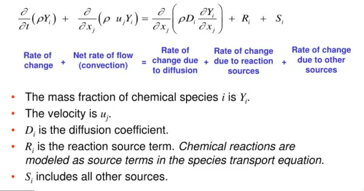
SAGE is very slow so in order to speed up SAGE there are several method,Re-solve method: To maintain solution accuracy it is recommended that resolve temperature is not greater than 2k
For solving ODE Newton Raphson solver which computes jacobian and the analytical Jacobian option is recommended for reaction in Arrhenius form.Grouping sells into bins which is based on two or more variables like temperature, equivalence ratio, reaction ratio etc. Bins calculate average quantities.Using the SAGE solver once per bins instead of once per cell which saves a lot of time.
TURBULENCE MODELLING:For turbulence RANS (Reynolds averaged Navier stokes equation) based K-epsilon turbulence model is used. K-epsilon turbulence model is used for high turbulent flow.
MESHING:
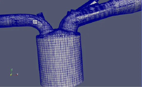
The converge has edge over other CFD software because of autonomous mess generation feature due to which it saves a lot of time for meshing complex geometries.In order to improve the accuracy of numerical simulation Converge uses AMR(adaptive mess refinement) technique. Adaptive Mesh refinement technique is used in cylinder and intake port region where the mesh need to refined locally. The mesh in other region is same as base grid size but in the intake port and cylinder region finer mesh size is used, hence AMR is used to monitor the curvature in temperature and velocity. In this problem temperature and velocity based adaptive mesh refinement is used which means that if the temperature and velocity curvature is greater than or equal to the sub grid scale of 1 than new mesh refinement region with embedded level 3 will generate. In the above model base grid size is 4mm.
RESULTS AND DISCUSSION
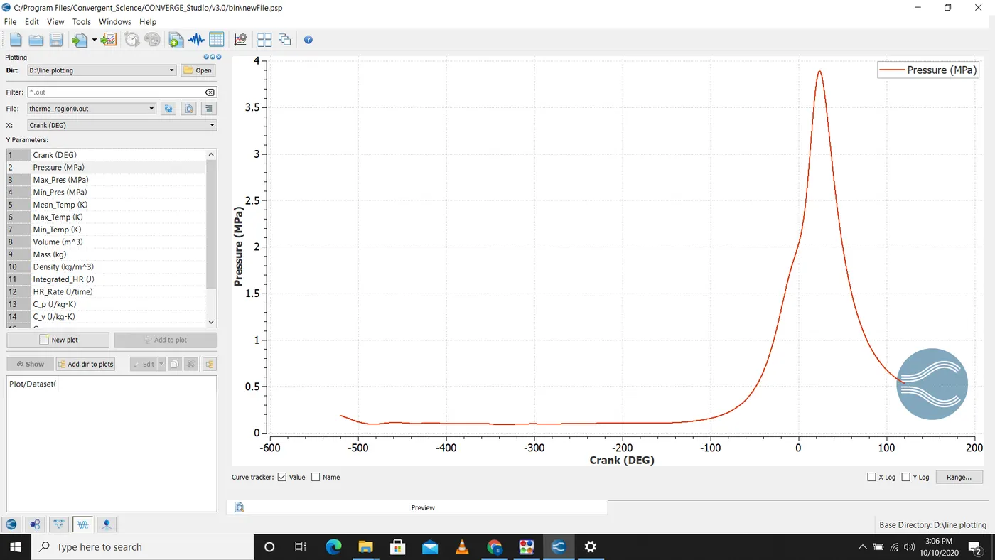
The Pressure vs crank angle shows similar trend to that of S.I engine and notice that combustion start when there is sudden increase in pressure value which is shown in the above figure.
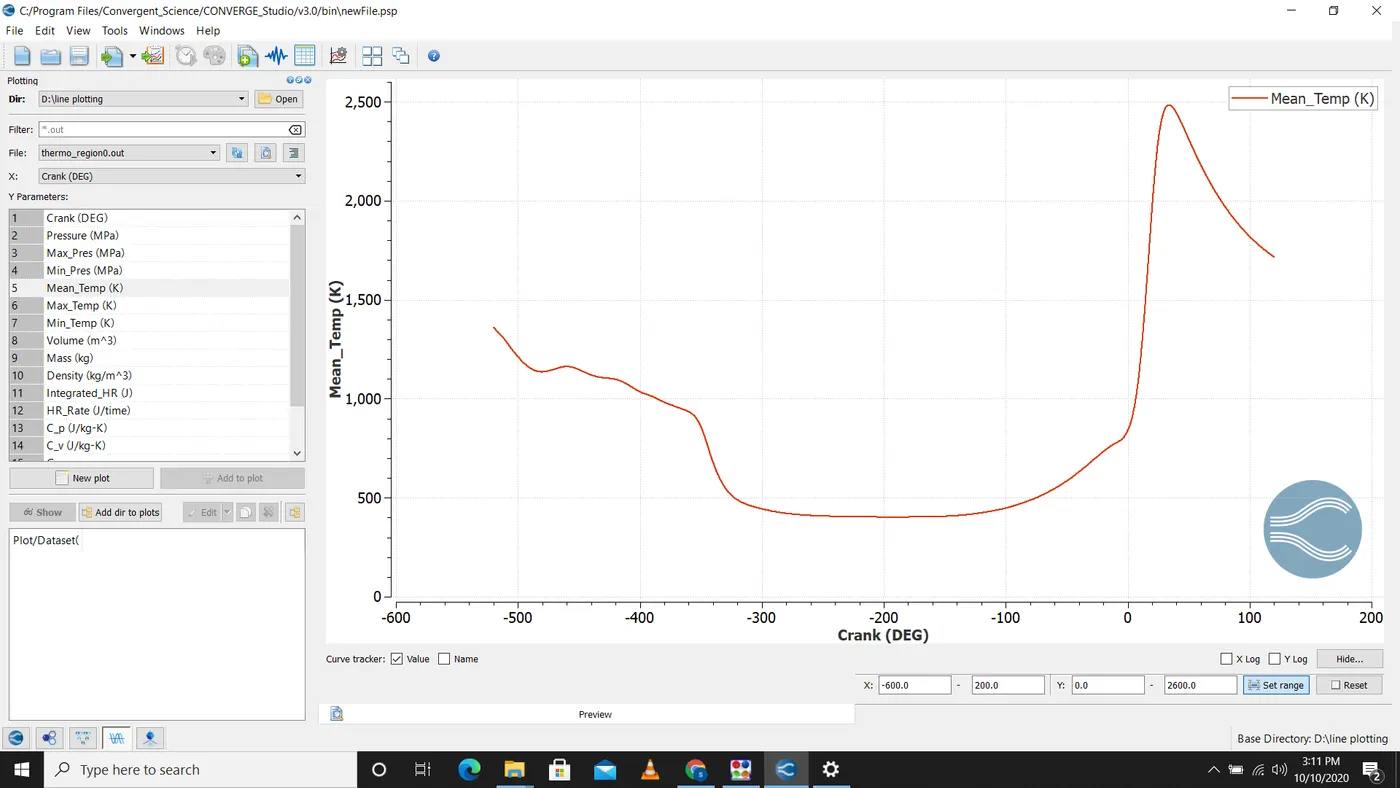
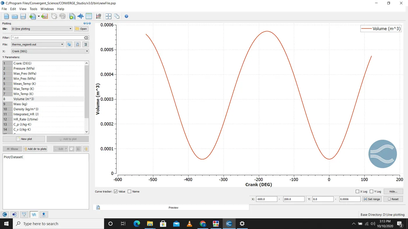
From the above graph we can calculate the compression ratio which is given by max volume/min volume
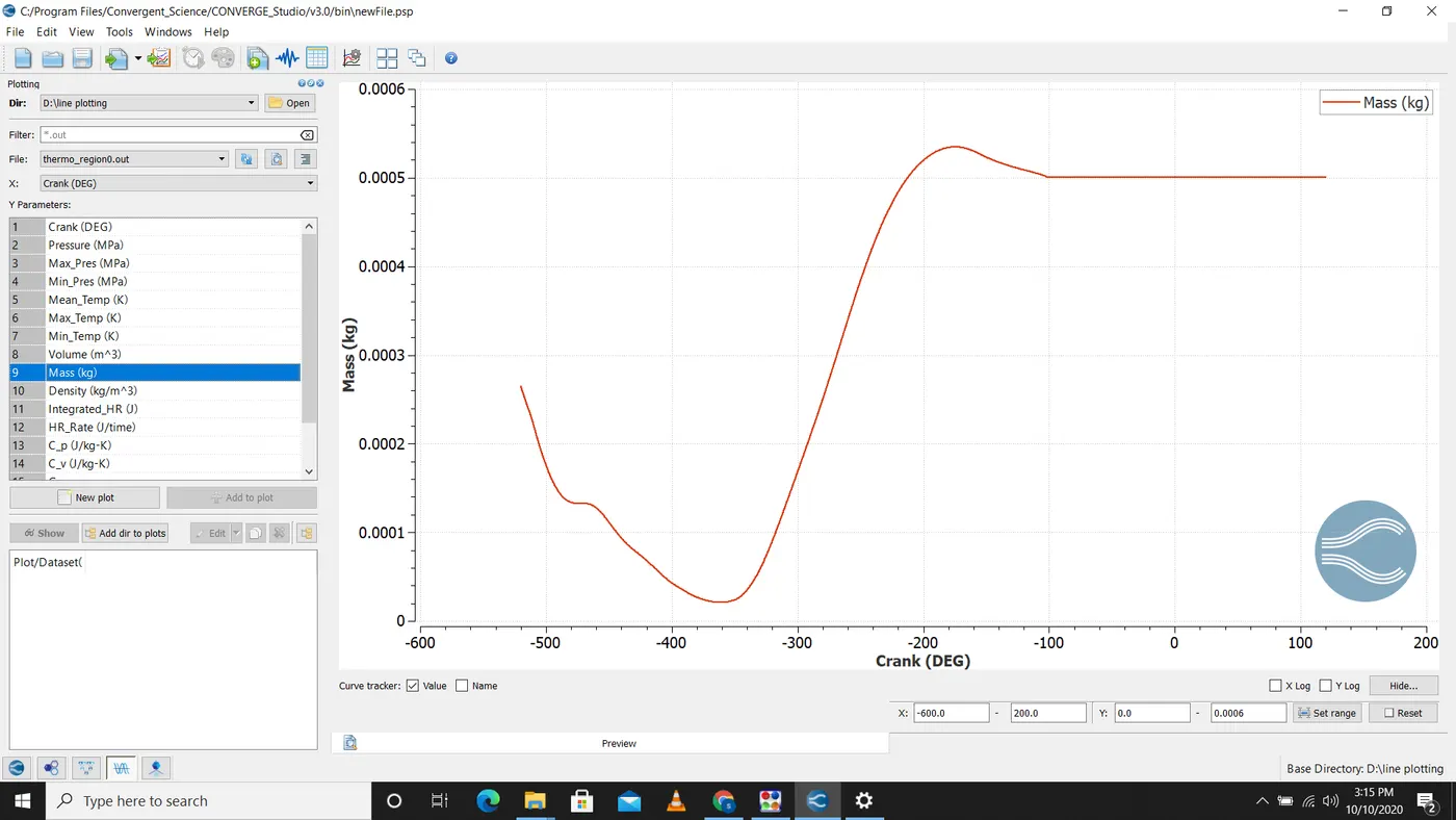
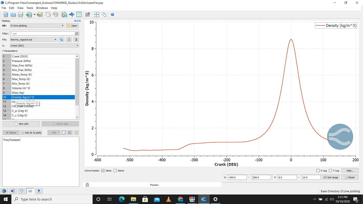
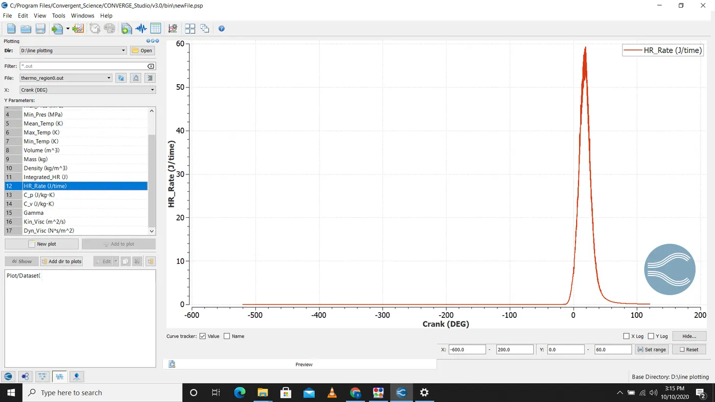
Heat release rate determine how much heat energy is required per crank angle
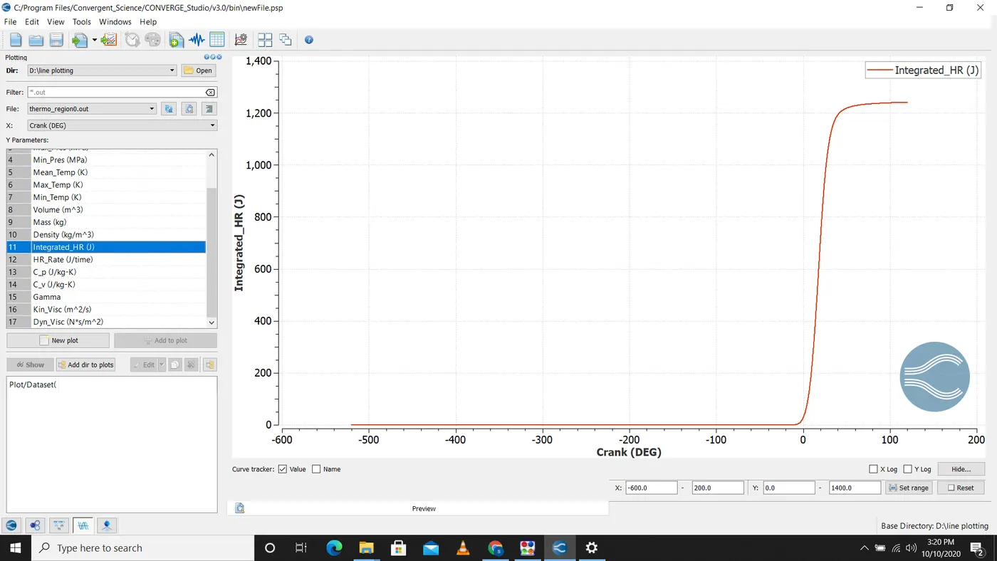
integrated heat release is the total heat energy released by combustion process.This value is important as it helps us to determine the combustion efficiency.
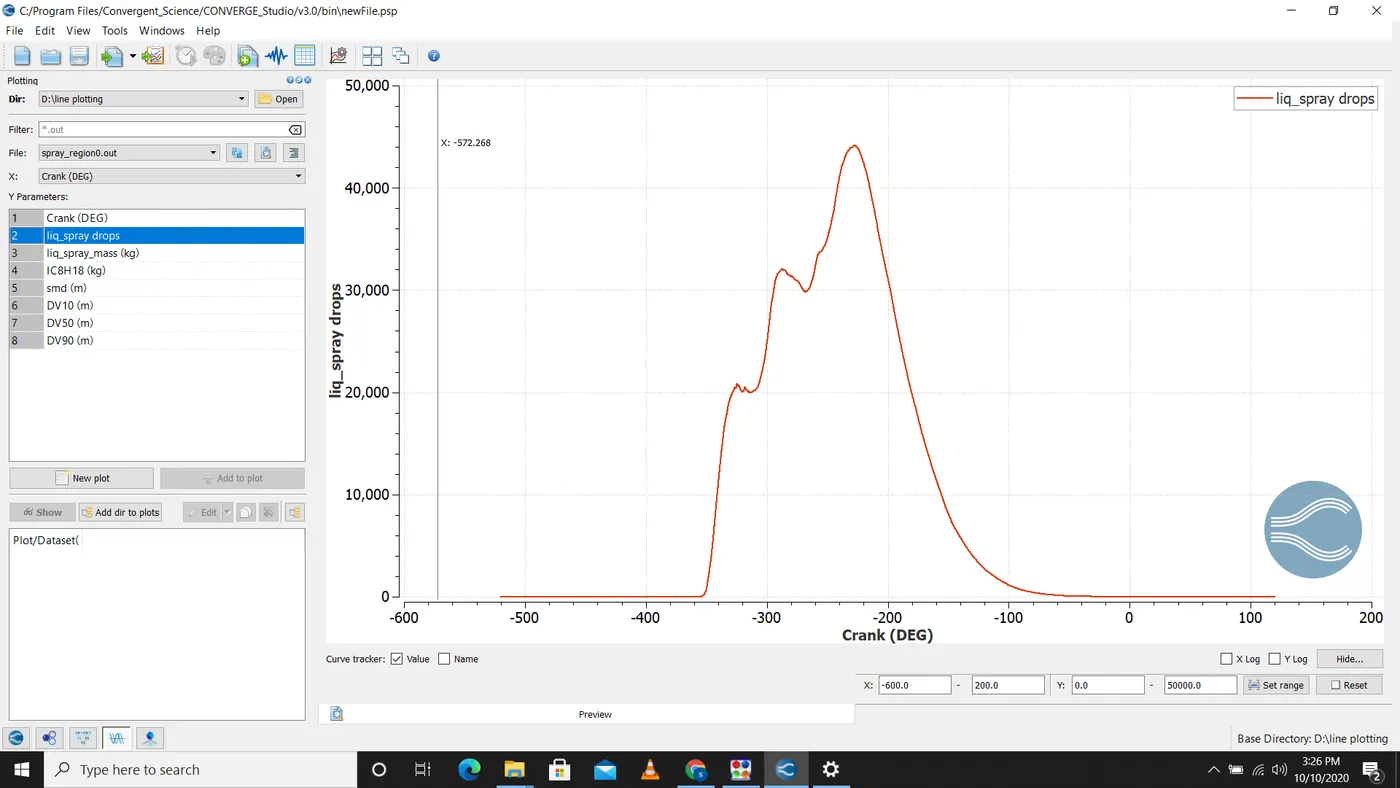
liquid spray drops determine the number of lagrangian parcel that are active in the domain.The parcel value drops due to vapourisation and combustion.Towards the end there is zero drops that means there is no unburnt hydrocarbon or fuel left.
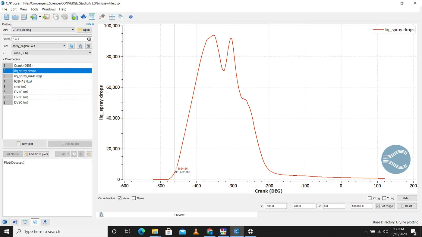
Region 3 is the region in the intake port which is attached to the combustion chamber.In this region there are some amount of fuel which are vapourised and some amount of fuel which gets trapped inside this region.
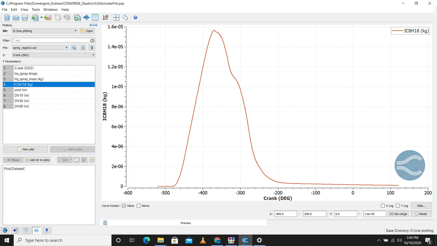
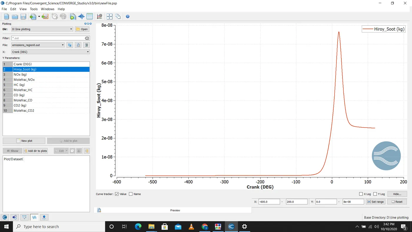
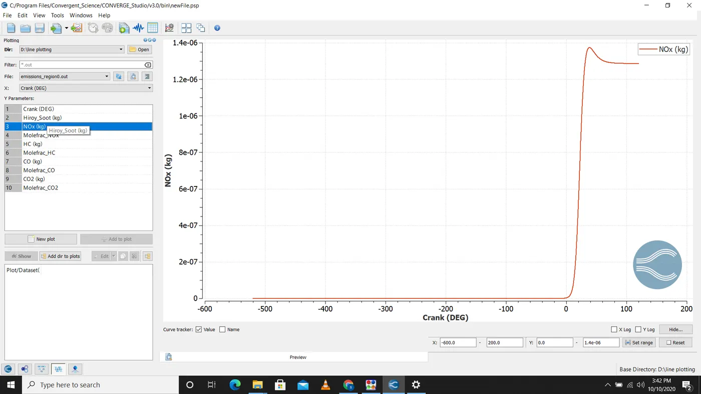
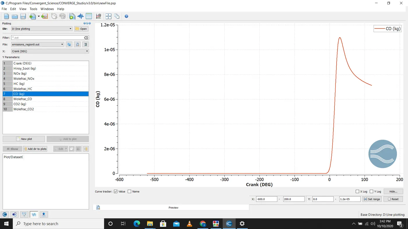
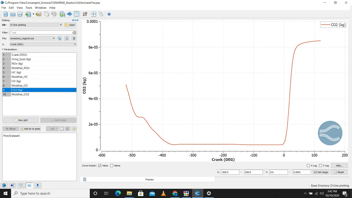
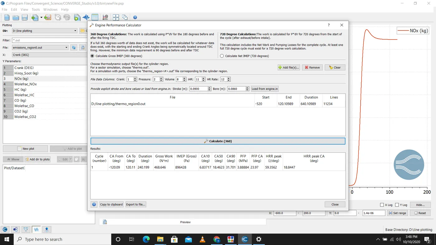
From the engine performance paramaters work output = 468.646
power = work done/time
3000 rpm = 50 rps
18000 degree per second
1 degree=1/18000
240 degree=1/18000*240=0.01333seconds
power=468.646/0.01333=35.148kw
power =(2*π*N*T)/60
T=111.90Nm
Combustion efficiency = Max heat released/mf*cv
mf=7.5e-4kg/sec
cv=45000KJ/kg
where cv=calorific value
combustion efficiency=1356/(7.5e-4*45MJ)=40.17%
We need to model wall heat transfer because during case set up we used stream id 0 which is used to solve navier stokes equation for fluid flow but to predict wall heat temperature we need to solve energy equation.Inside the cylinder region due to spark ignition and combustion the flame propagate and travels towars the cylinder liner which than transfer heat to the cylinder wall by convection and conduction and also there is turbulece due to combustion.Because of various combustion and flame propagation and turbulence it is very difficult to predict wall heat transfer using CFD simulation so we need prper model to predict wall heat transfer.