Week 10 - MRF Electronic Cooling Simulation
AIM : To Simulate a electronic cooling of the given cabinet via Forced Convection by implenting the MRF Model technique in Ansys ICEPAK.
OBJECTIVES :
- Unpacking the given .tzr file of the Electronic device setup.
- Setting up the MRF model across the Fan Geometry.
- Create optimal meshing for the model.
- Setup the model for the Analysis.
- Run the simulation and Post Process the results.
INTRODUCTION :
The Moving Reference Frame (MRF) approach is a steady-state method employed in industrial Computational Fluid Dynamics (CFD) to model problems with rotating parts. It is considered to be less computationally expensive and yet accurate enough for most industrial problems.
This strategy’s underlying principles are straightforward but elegant. During the meshing phase, a small volumetric zone of mesh cells is produced around the spinning body, and the MRF zone encompasses this area.
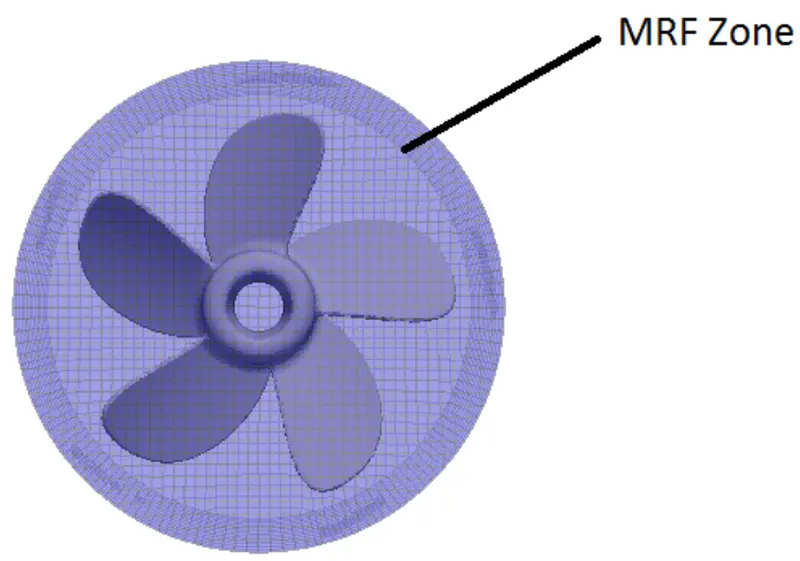
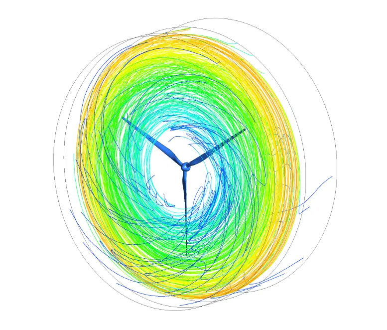
The MRF zone is rotated around the body’s axis while the body remains still during the simulation phase. In a reference frame that rotates or moves at the same speed as the rotating or moving geometry, governing equations are solved. On a physical level, it means that we see the flow field around the moving body while seated on it. The flow field becomes stable concerning the geometry as a result.
STEPS / PROCEDURE :
1) Geometry
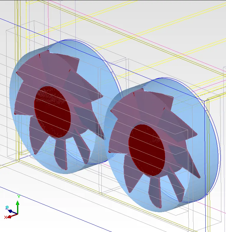
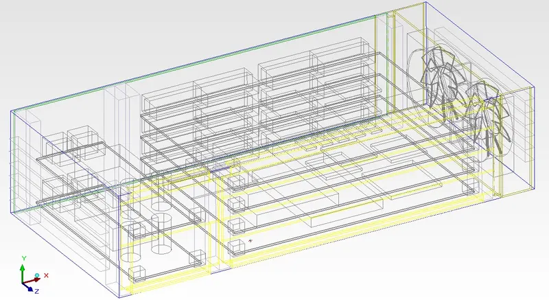
The MRF .tzr file is unpack in the Icepak Electronic Device which is to be analyzed.
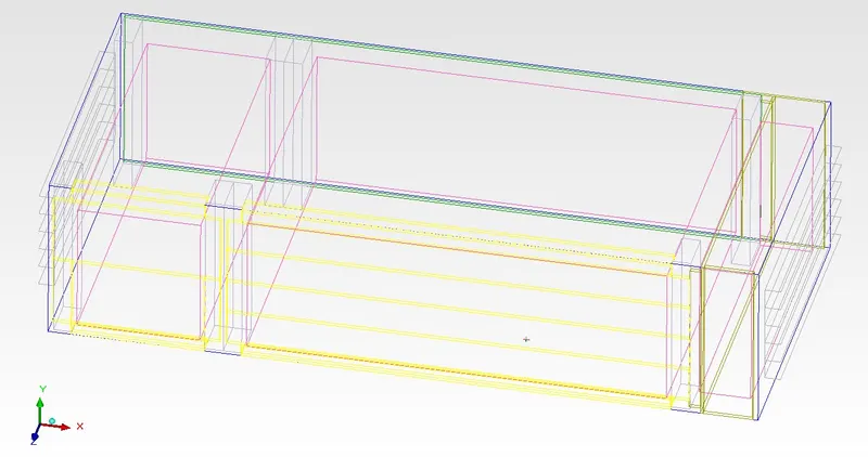
The geometry of the cad model is in the dimension of 730x12x180, with inlet and outlet vents.
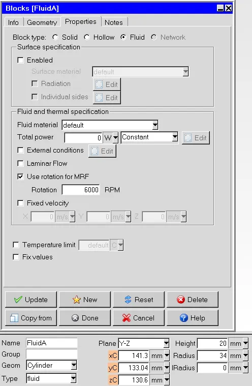
The fluid region around the fan is created.
2) Meshing
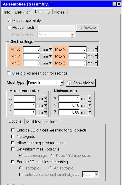
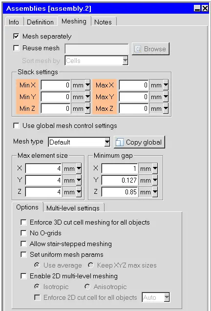
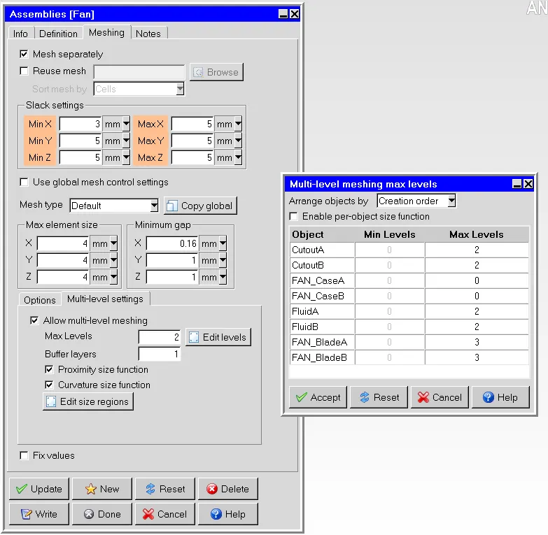
We have created a non-conformal mesh assembly accross the component assembly. To have fine mesh near to the components and coarser mesh across the enclosure and its ambient.
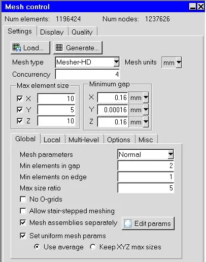
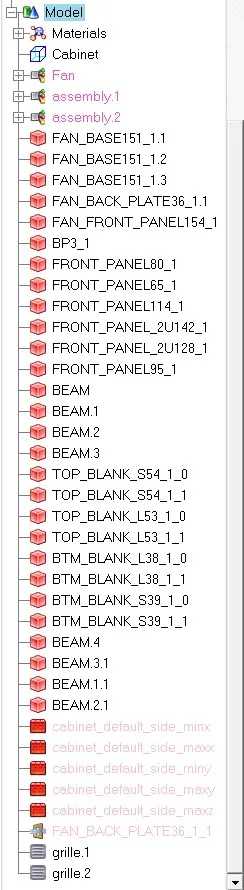
Following is setting used for global mesh and the assembly mesh settings -
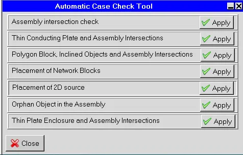
Case check tool in Macros options-

Mesh Quality Verification-
Following is the surface mesh of the Case Setup -
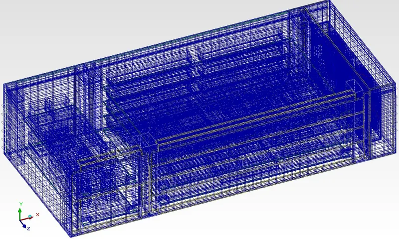
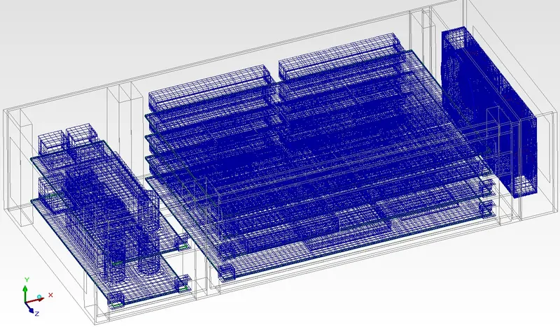
Following is the visualising the mesh inside the cabinet-
- Cut plane of XY plane at 50% of the cabinet in Z-direction from origin (Top Plane)
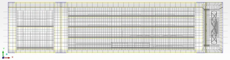
- Cut plane of YZ plane at 50% of the cabinet in X-direction from origin (Front Plane)
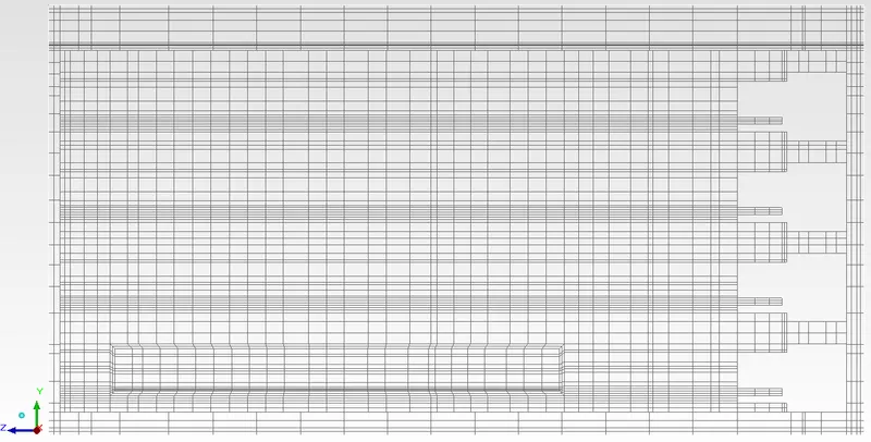
- Cut plane of XZ plane at 50% of the cabinet in Y-direction from origin (Right Plane)
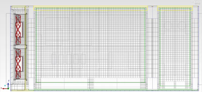
- Mesh across the the Fan Geometry and MRF Region
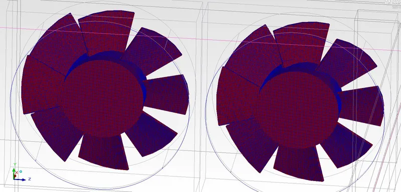
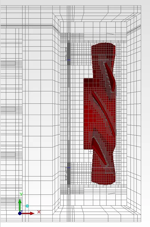
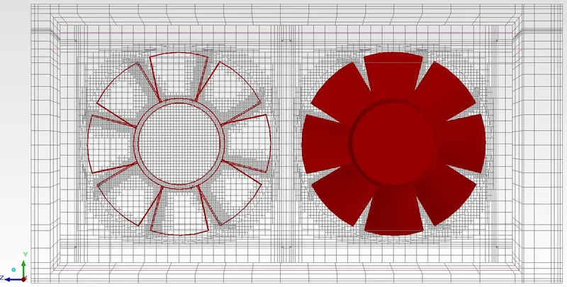
Mesh Quality Parameters -
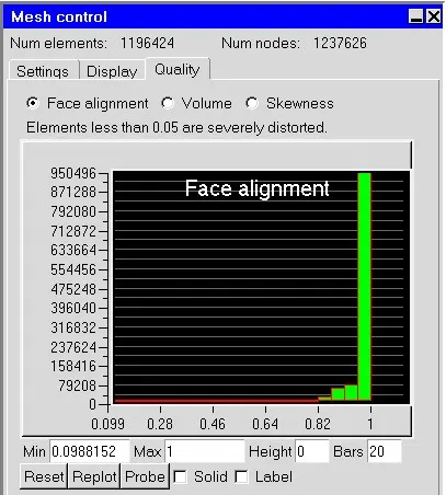
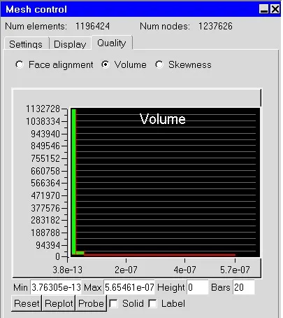
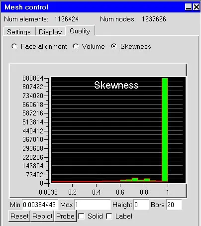
We can the mesh quality is very satisfied. 90% of the mesh cell are lying on good quality range.
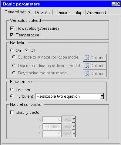
Solver Settings -
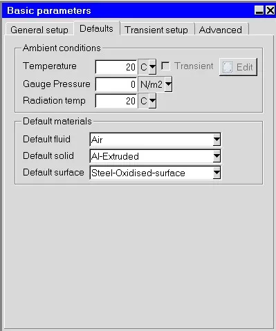
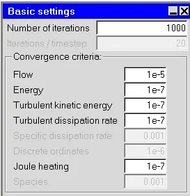
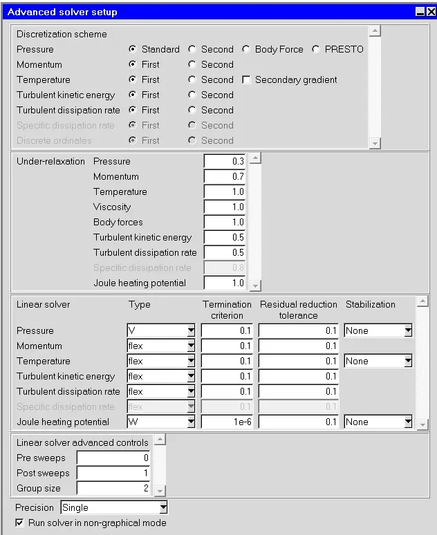
POST PROCESSING :
Outputs
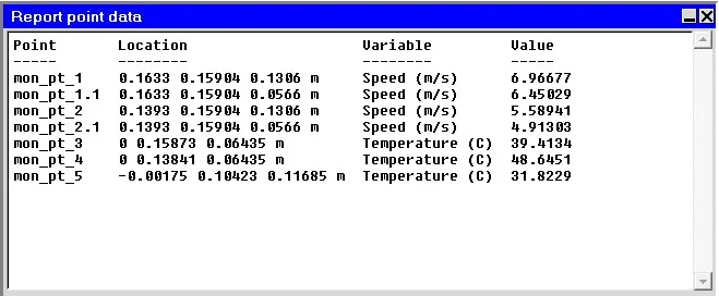
Residuals and Monitor Points -
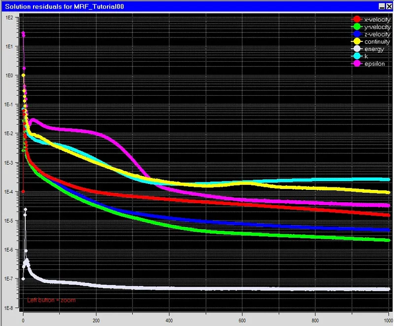
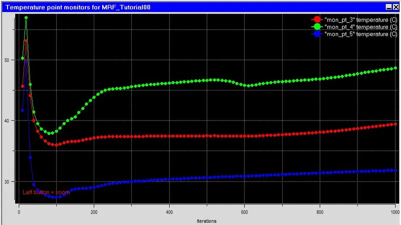
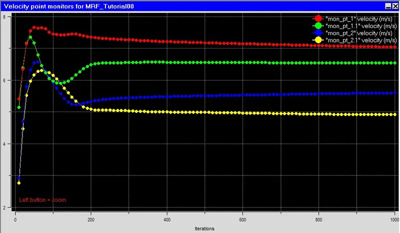
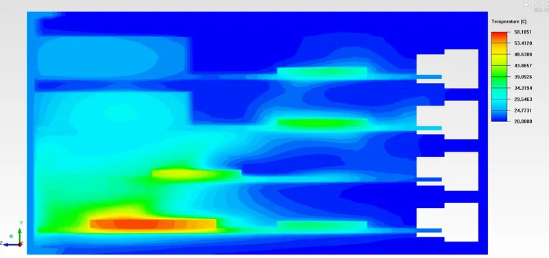
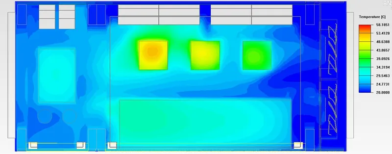
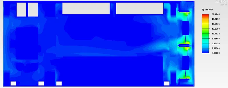
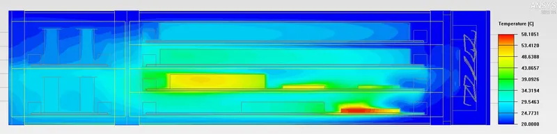
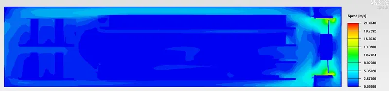
Temperature and Velocity Contours -
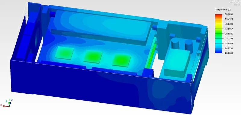
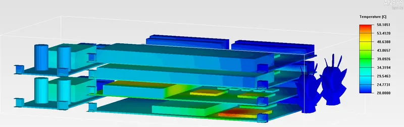
Along X Direction-
Along Y Direction-
Along Z Direction-
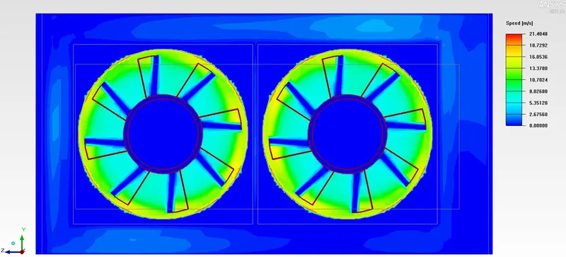
Velocity Across the Fan Blades -
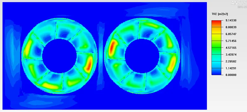
Turbulent Kinetic Energy at Fan Region -
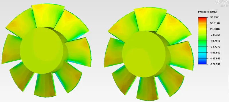
Pressure on the Blades -
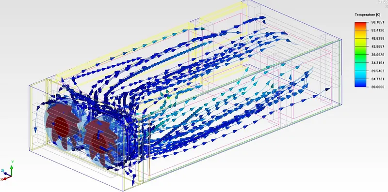
Particle Trace / Streamline Visualisation of the Velocity -
RESULTS :
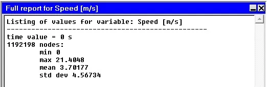
The Following are the results of the simulation, generated simulation report Monitor point, Velocity and the Max. temperatures of the different bodies acting in the simulation -
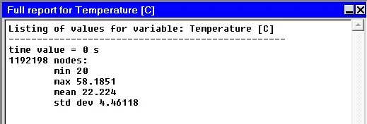
The maximum temperature within the computational domain is 58.1851 Deg.C.
The maximum air velocity within the computational domain is 21.4048 m/s.
CONCLUSION :
We have successfully performed the simulation analysis of the Forced Convection cooling via MRF approach.
The solver was set up using suitable settings to incorporate the physical phenomena.
We were able to generate required contours for temperature, speed, Streamline/particle traces, etc.
The following conclusions can be drawn based on the simulation results after running upto 1000 iterations :
- We can see the temperatures attained are realistic and all the residuals are less than 10e-3.
- Maximum air velocity within the computational domain is 21.4048 m/s.
- Maximum temperature within the computational domain is 58.1851 Deg.C.
The MRF approach gives or predicts better information about the particle movements, temperature and velocity distribution in the vicinity of the fan when compared with the normal fan available in ICEPAK library.
REFERENCES :
Multiple Reference Frame (MRF) Approach for Turbomachinery, https://youtu.be/oa-xcE0_0UY
How to model Rotating Elements in CFD, https://youtu.be/zFSXtRGk_H8