Week 10 - MRF project
Aim:
Unpack Icepak model of fan blades and create the rotating MRF fluid blocks to create flow in the model. Perform problem setup and solution settings for an MRF model, Use good meshing technique for good results
Description:
An Icepak 3D fan object may sometimes behave differently from real fan behavior. Typically this is due to flow features like swirl and centrifugal spread resultant from the spinning fan rotor as well as the rotor blade geometry. In an Icepak fan based setup, this swirl is estimated and calculated off a 2D annular flow face rather than off the physical surfaces of the blade.
The MRF approach allows for a more accurate representation of the internal geometry of the fan and therefore results in a better modeling of the flow features. In Icepak MRF simulations, the actual blade geometry is modeled as a CAD block object and a fluid cylinder rotates into contact with the surfaces to create a spinning flow.
Moving reference frame:
1.The Moving reference frame approach is a steady-state method employed in industrial Computational Fluid Dynamics (CFD) to model problems with rotating parts.
2.It is considered to be less computationally expensive and yet accurate enough for most industrial problems.
3.The underlying physics behind this approach is simple.
4.A thin volumetric region of mesh cells is created around the rotating body during the meshing phase. This region is known as the MRF zone.
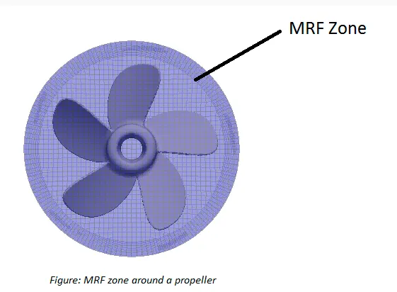
5.During the simulation phase, the MRF zone is rotated about the axis of the body and the body is kept stationary.
6.In order to preserve the direction of Coriolis Forces on the body, the rotational velocity of the ball is reversed in the MRF zone.
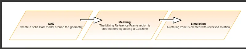
Flow chart:
Geometry:
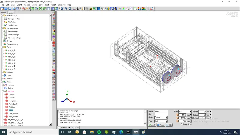
1.Unpack geometry into icepak
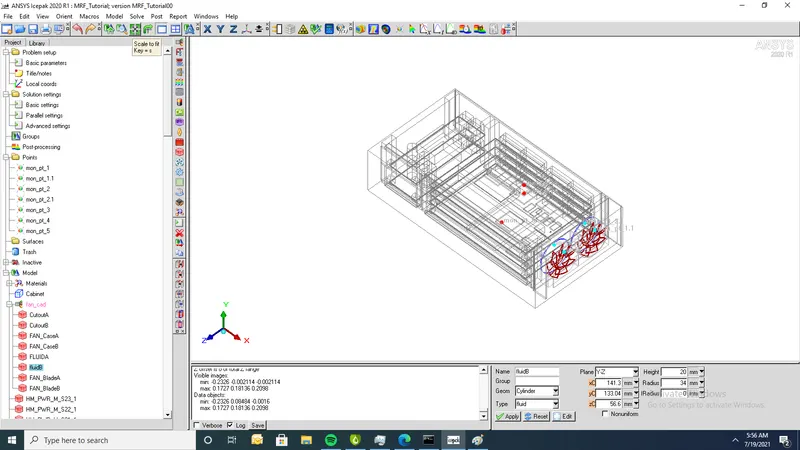
2. Create assembliey based on priorties of meshing
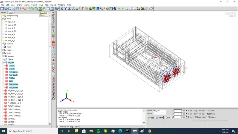
3. Apply geomtry to fluid b which is surrounded around fan b
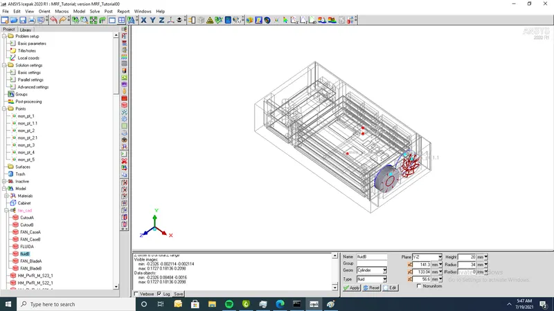
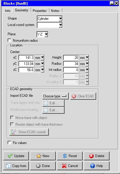
4.Geometry of fluid B
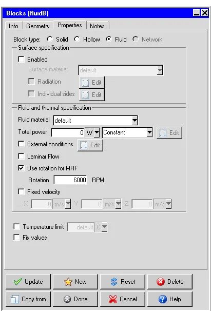
5.Properties of fluid B fan rotating with 6000 r.p.m
6. For fluid A geometry is translated by z=56 and fan rotating with R.p.m as shown
7. Fluid A & Fluid B are shown as follows
Meshing:
1.Before generating mesh, created assembly is meshed seperately and multi level meshing also performed
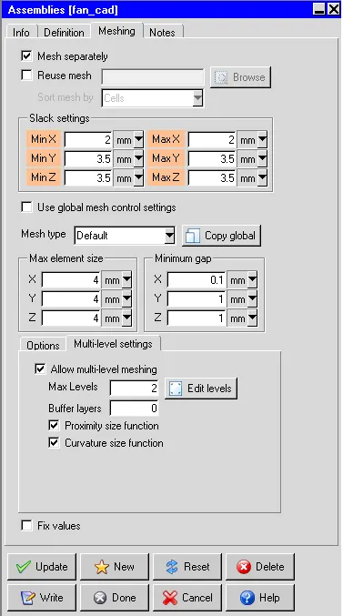
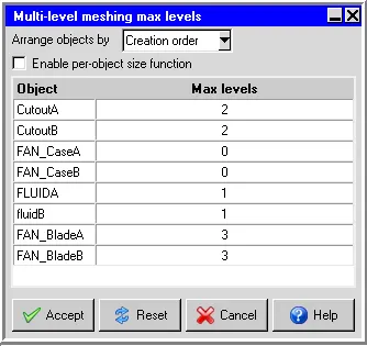
2. Enable Multi level meshing
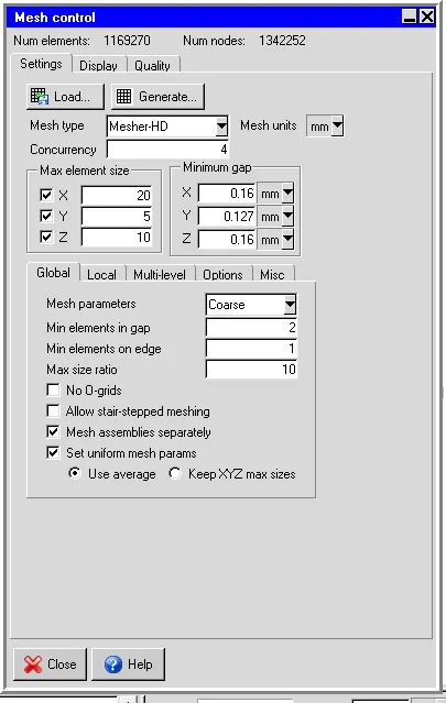
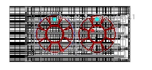
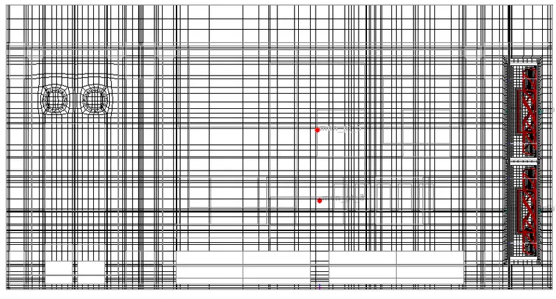
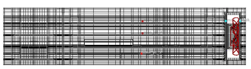
2.Generate mesh after multilevel meshing and it shows No of Elements=1169270 and No of Nodes= 1342252
3.Cutplane through x-plane
4. Cutplane through y-plane
5.Cutplane through Z-plane
Setup:
1.solve for velocity,Pressure and temperature
2. Flow has inlet/outlet (Forced convection)
3.Set flow regime as turbulent
4. Turbulent model (K-epsilon)
5.ignore heat transfer due to radiation
6.Apply steady state
7.Run 500 iterations
Contours:
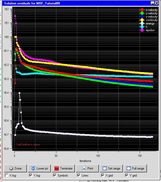
Residuals:
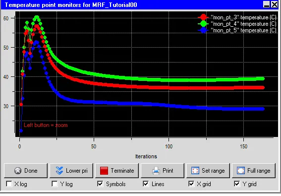
Temperature monitor points:
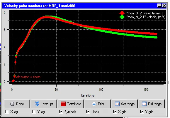
Velocity monitor points:
Temperature contour:
1.Min temp of model=19.99oC and max temp=48.87oC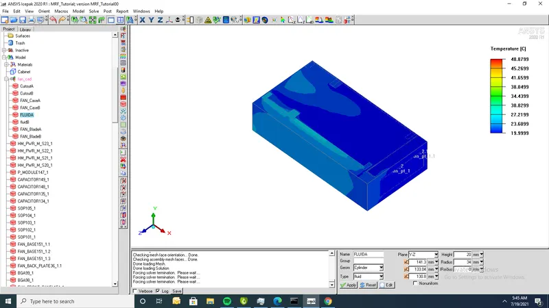
Cutplane temperature:
1.Cutplane through x
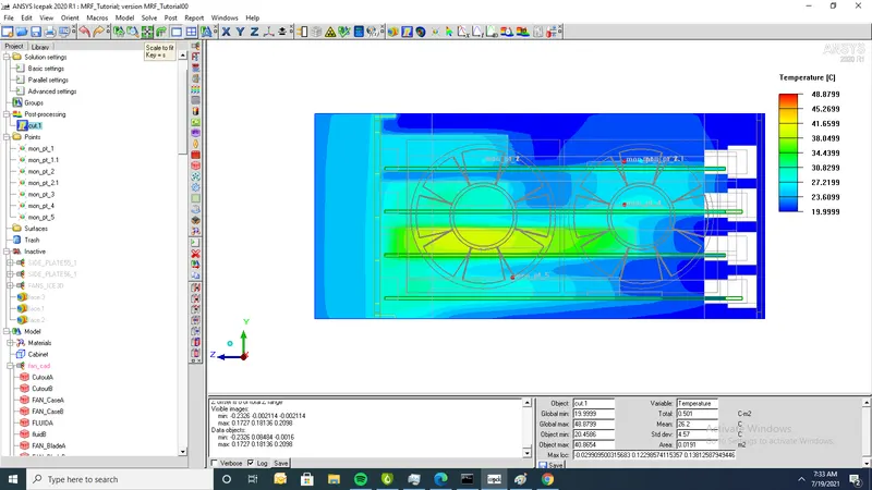
2. .Cutplane through y
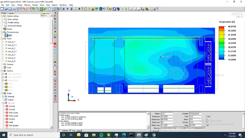
3..Cutplane through Z
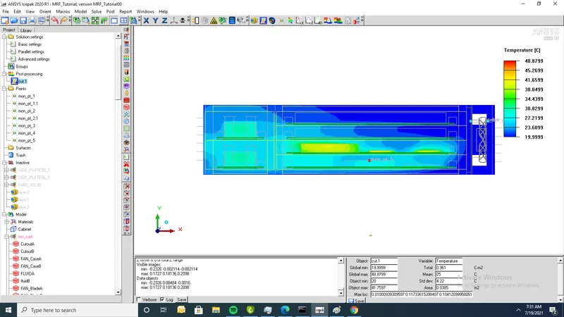
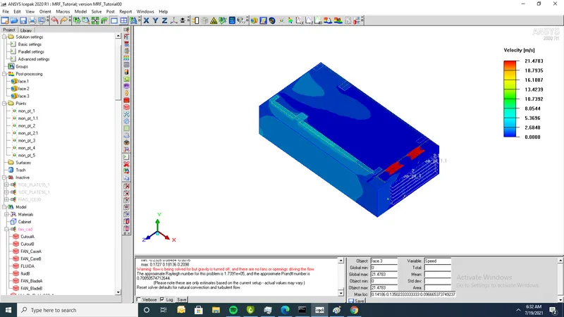
2.Min velocity of contour=om/s and Max velocity=21.4783m/s