Week 10: Modeling and Simulation of flow around an Ahmed Body
AIM
To create a ahmed body model, along with the virtual wind tunnel and run a external aerodynamics simulation.
To post-process the result obtained from simulation and plot velocity along vertical direction at different points in the flow path:
To calculate the drag coefficient.
Objective:
To simulate flow around an Ahmed body.
Creating the CAD model using any CAD package
Setup a Coarse CFD simulation
Setup the virtual wind tunnel as shown in the video.
Apply the right boundary conditions and solver settings
= Use a coarse mesh to demonstrate that your setup runs successfully.
You need to show an animation of the velocity distribution on a cutplane. This cutplane should cut the ahmed body model in two symmetric pieces.
You need to show an animation of the pressure distribution on a cutplane. This cutplane should cut the ahmed body model in two symmetric pieces.
o Enable wall-averaged outputs to measure the drag and lift forces
Calculate the steady state drag force value and explain your calculation procedure. Calculate the drag co-efficient using paraview and explain your calculation process in detail.
INTRODUCTION
Ahmed body is a geometry which represents a generic car body. We can consider it as a blunt body which has a rough geometry resemblance that of a car, it was first developed and experimented by s.r Ahmed and hence it is named as ahmed body. Significance of an ahmed body is that, suppose we have developed a CFD code, which we need to run simulations around a new model car which is to be developed, so in that case we can use ahmed body to check whether the codes that were developed is good. We can use the codes and run simulations around a ahmed body to capture flow parameters in a turbulent flow. If we are able to validate the numerical results then we can use the codes to develop the new model car.
Ahmed body
The Ahmed body is a generic car body (a simplified vehicle model). The airflow around the Ahmed body captures the essential flow features around an automobile and was first defined and characterized in the experimental work of Ahmed. Although it has a very simple shape the Ahmed body allows us to capture characteristic features that are relevant to bodies in the automobile industry. This model is also used to describe the turbulent flow field around a car-like geometry. Once the numerical model is validated, it is used to design new models of the
car.
Ahmed body is simplified car model created by Ahmed et in the 1980s to investigate the behaviour of newly developed turbulence models for complex geometry cases. The Ahmed body is made up of around front part, a movable slant plane placed in the rear of the body to study the separation phenomena at different angles, and a rectangular box, which connects the front and rear slant plane as shown. Ahmed body is a simplified model of a car body, but it demonstrates all the flow features involved in an actual case of a moving car Cument vehicle development needs a strong background in aerodynamics to improve flow control by means of active or passive control devices. The complexity involved in the automobile design especially due to the great number of accessories and devices that form its geometry makes the validation tasks unaffordable. The Ahmed model is a simple geometric body that retains the main flow features especially the o wake flow where most part of the drag is concentrated and it is a good candidate to be used as a benchmark test.
The Ahmed body represents a simplified, ground vehicle geometry of a bluff body type Its shape is simple enough to allow for sure flow simulation but retains some important practical features relevant to automobile bodies Selection of the configuration of this body governed by the requirement that it should generate the essential features of a real vehicle flow field except for the flow Feshat occur due to rotating wheels, engine and passenger compartment, rough underside and surface projections.
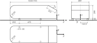
Geometry and wind tunnel:
To capture the external aerodynamics, wind tunnel creation is a must. The size of the wind tunnel depends on the geometry and the inlet velocity Generally, the length of the wind tunnel is (10 to 50) times the length of the body of the model
For this project, the following methodolgy is used:
The boundary layer thickness formulation used here is:
88-0.382 Re
here, &, Re, is the boundary layer thickness, local reynolds number, and the distance where the flow is developed fully. Local reynolds number is given by. Re, Re, = p-U-z
H
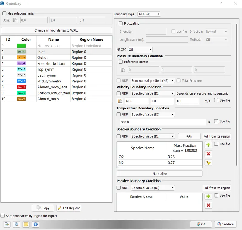
In this project, the boundary layer thickness is given as, 30 mm, and the inlet velocity is 40m/s.
Boundary flagging and case setup:
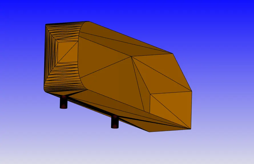
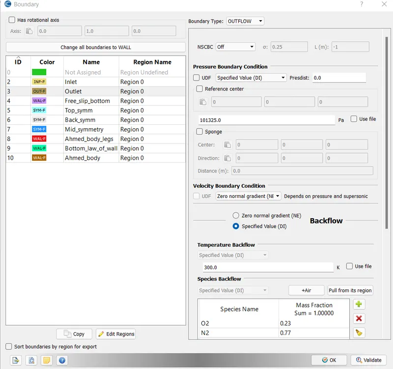
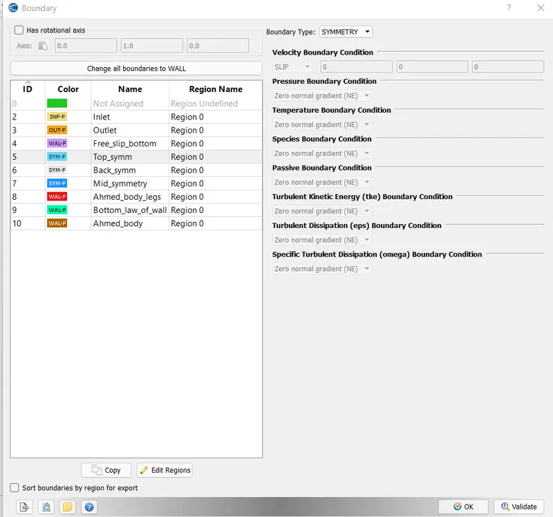
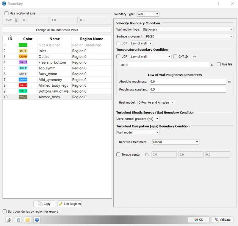
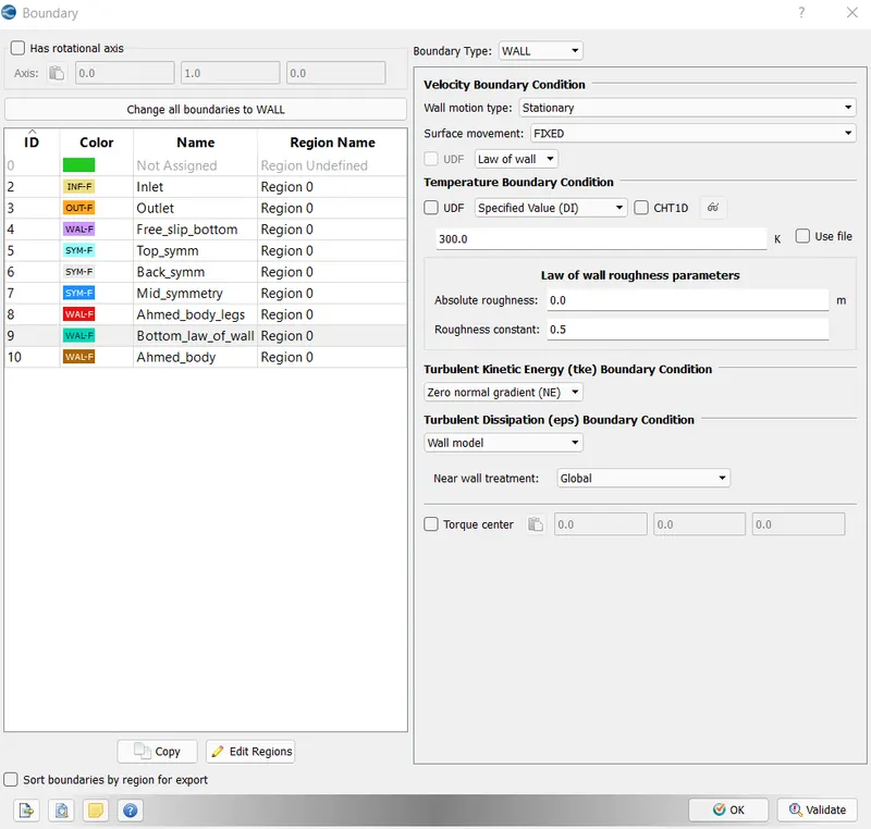
1. After uploading the STL file containing the ahmed body with its enclosure. Boundary flagging is done before moving to the case setup. 2. The side and top walls can be set to symmetry BC. Bottom surface has to 2 sides, one with slip conditions at the inlet and no slip as the ahmed body approaches.
3. After flagging all the boundaries, transient state solver case setup is initialised.
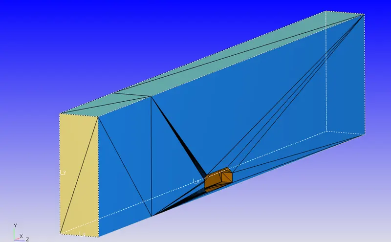
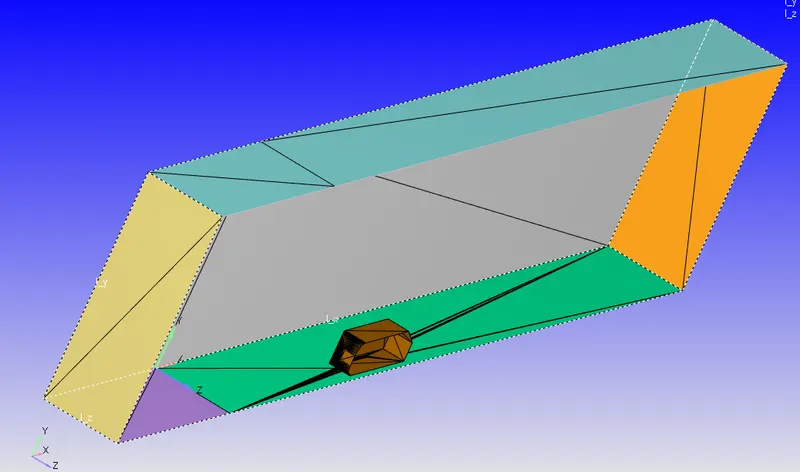
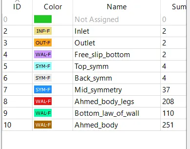
Case setup:
Application type:
This is atime based simulation. This donot include any ic engine parts.
. Materials:
Under the materials tab, there are three options:
The preferred mixture selected is air. reaction mechanism is turned off and the species is turned on.
1) Gas simulation:
Equation of state - Redwich_Kwong
Critical Temperature: 133K
Critical Pressure = 377000 Pa
2) Global transport parameter.
Turbulent Prandtl number: 0.9
Turbulent scmidt number: 0.78
3)Species:
The species selected are 02 and N2.
Simulation parameters:
1) Run parameters.
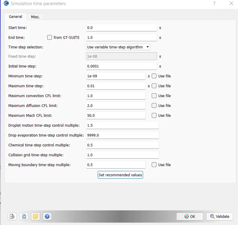
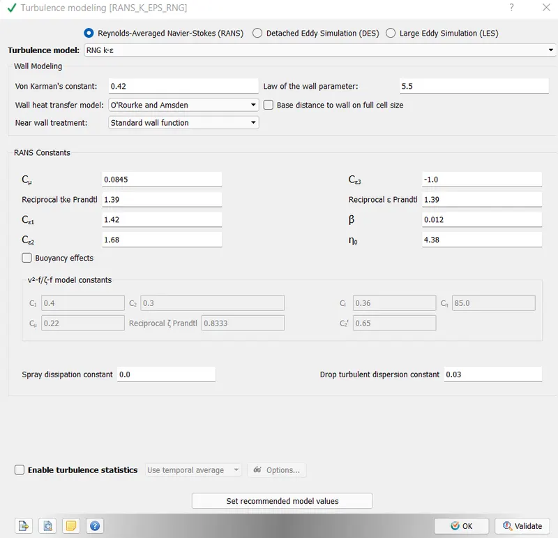
solver type is transient. Full hydrodynamic and a compressible flow simulation is carried out.
2) simulation time parameters.
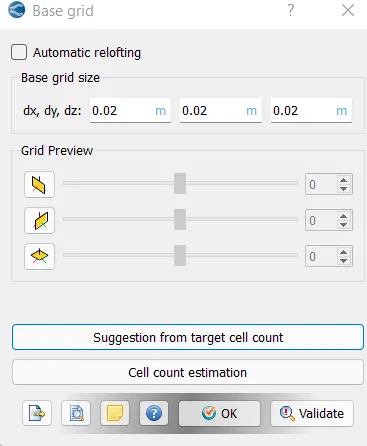
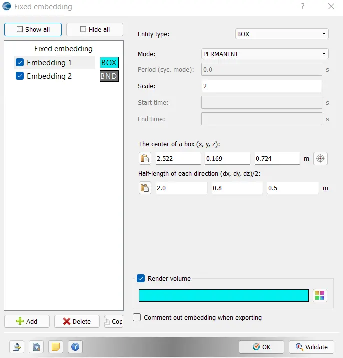
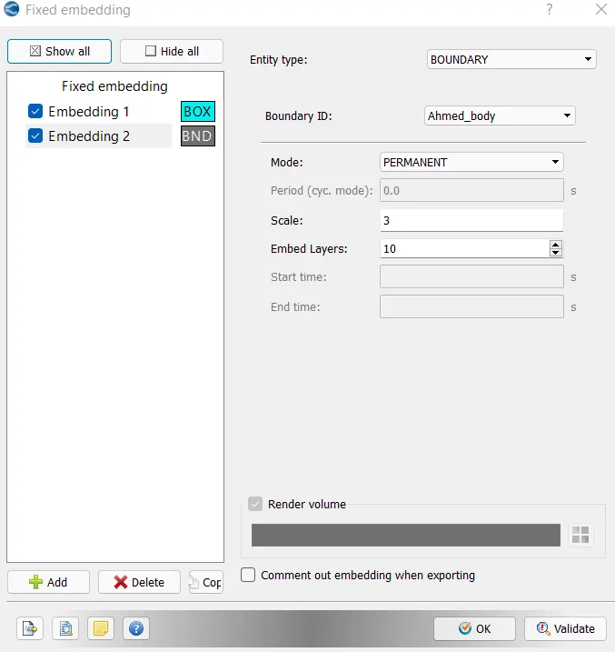
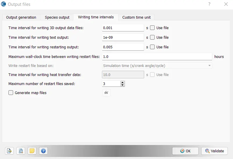
Results:
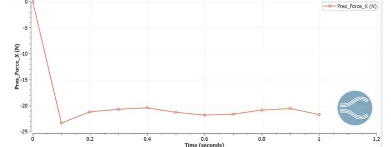
Drag force
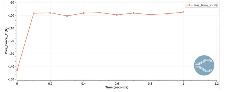
Lift force
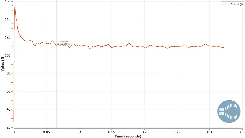
Y+ plot
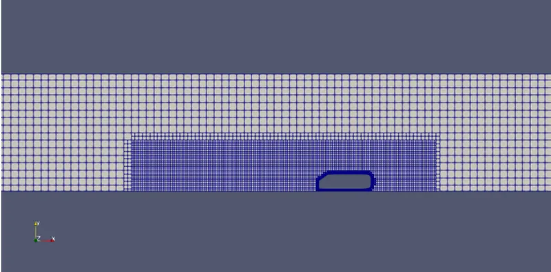
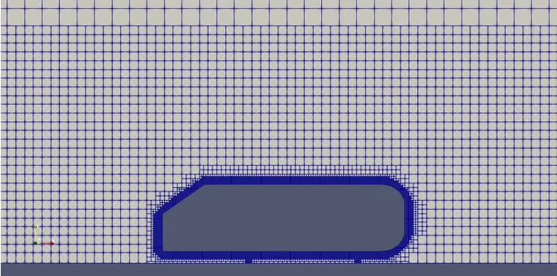
Meshing
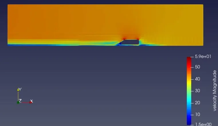
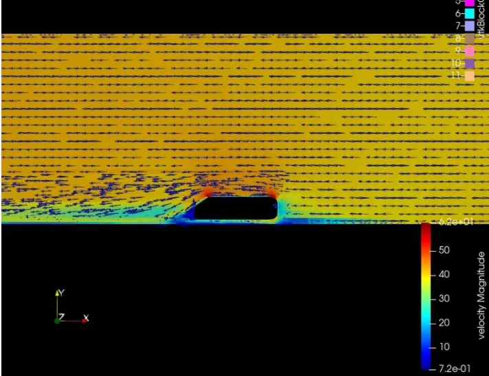
Velocity counter:
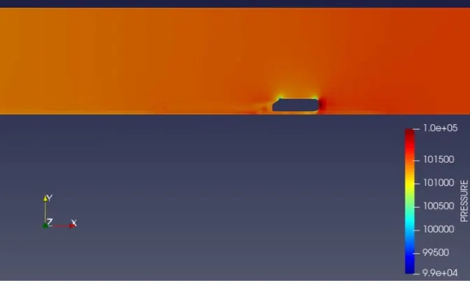
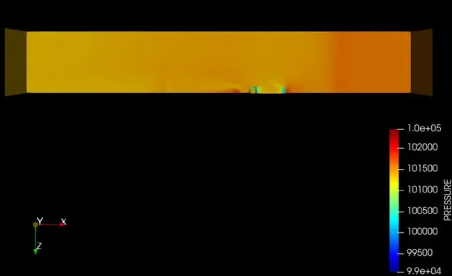
Pressure counter:
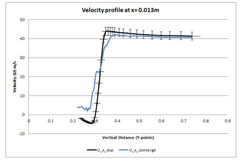
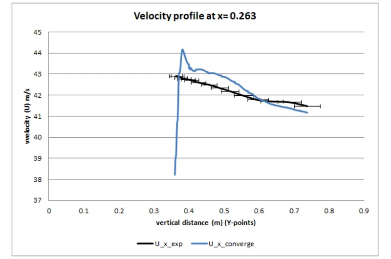
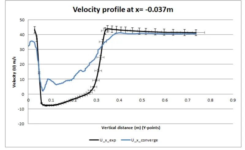
Compansion of simulation results with Experimental data using line probes at different locations of X
The origin of the simulation geometry is located exactly as the experimental setup, but the velocity is flowing in negative x-direction therefore the line probes location are opposite in signs to that of experimental line probes.
Conclusions:
The total drag coefficient of the Ahmed body is the key measurement for this simulation.
It is made up of measurements for the pressure coefficients in the front, slant, and base of the body as well as the body's skin friction:
When the body is moving at 40 m/s (although the science of air moving around stationary body or body moving around the stationary air is same) it encounters a resistive foroce of 38.8 Nie.. the drag force.
Even better simulation results can be achieved with increase computational power and decrease in grid size.
The plots show that the simulation results are coinciding with some parts of the plot which indicates that out simulation is performed correctly.
To decrease the Drag, we can decrease our slant angles therefore reduced flow separation is achieved at the rear end of the car, which gives us better performance efficiency of the vehicle.
Examining the velocity profile it is seen that there is a region where there is circulation and the region is called wake region. This region causes drag
The negative lift force says that it is down force. This attributes to the fact the model stays at the ground.
The shape of the body or the passenger vehicle may be optimized to reduce the lift force.